
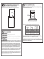
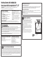
BEFORE YOU BEGIN
Read these instructions completely and
carefully.
•
,03257$17³ Save these instructions
for local inspector’s use.
•
,03257$17³ Observe all governing
codes and ordinances.
• Note to Installer – Be sure to leave these
instructions with Consumer.
• Note to Consumer – Keep these instructions
for future reference.
• Skill level – Installation of this appliance
requires a qualified installer or electrician.
• Proper installation is the responsibility
of the installer.
• Product failure due to improper installation
is not covered under Warranty.
• Product is for indoor use only.
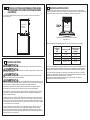
Installation Instructions
27” & 30” Electric Built-In Wall Ovens
FOR YOUR SAFETY:
WARNING
:
Before beginning the installation, switch power off at the service panel and
lock the service disconnecting means to prevent power from being switched on accidentally. When the
service disconnecting means cannot be locked, securely fasten a prominent warning device, such as a tag,
to the service panel.
Be sure the oven is securely installed in a cabinet that is firmly attached to the house structure.
Weight on the oven door could cause the oven to tip and result in injury. Never allow anyone to climb, sit,
stand or hang on the oven door.
Make sure the wall coverings, counters and cabinets around the oven can withstand the heat
(up to 200°F [93.3°C]) generated by the oven.
Questions? Call 1.800.GE.CARES (1.800.432.2737) or visit www.GEAppliances.com
In Canada, call 1.800.561.3344 or visit www.GEAppliances.ca
MATERIALS YOU MAY NEED
Junction Box
Wire Nuts
Strain Relief Clamp for 1/2” Conduit
36” (91 cm) of String
TOOLS YOU MAY NEED
1/8” Drill Bit and Electric or Hand Drill
Phillips Screwdriver
Wire Strippers
7/16” Nut Driver
T20 Screwdriver (hinge bracket)
1/4” Nut Driver
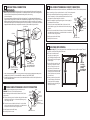
1
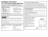
REMOVE PACKAGING MATERIALS
Failure to remove packaging materials could result in damage to the appliance. Remove all packing
parts from oven, racks and heating elements. Remove protective film and labels on the outer door
and control panel. Also, remove plastic on trims and panel, all tape around the oven and any shipping
screws securing the oven to the base pad. Open oven door and remove literature pack and oven
racks. Remove the bottom trim from the top of the oven. It will be installed at the end of the installation
process. The trim is wrapped separately and taped to the top of the unit. Remove pedestal rails from
seperate box and set aside (30” Double Wall Ovens Only).
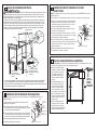
2
PREPARE THE OPENING
NOTE: If the cabinet does not have a solid bottom, two
braces or runners must be installed to support the weight
of the oven. For single ovens, the runners and braces
must support 200 lbs (91 kg). For double ovens, the
runners and braces must support 375 lbs. (170 kg).
NOTE: If marks, blemishes or the cutout opening are
visible above the installed oven, it may be necessary to
add wood shims under the runners and front trim until
the marks or opening are covered.
NOTE: If the cabinet does not have a front frame and
the sides are less than ¾” (1.9 cm) thick, shim both sides
equally to establish the cutout width.
ATTENTION INSTALLER: All electric wall ovens must be hard-wired (direct-wired) into an
approved junction box. A plug and receptacle is NOT permitted on these products.
Suitable
Bracing
to Su
pp
ort
C
L
2" x 4" (5 cm x 10 cm)
or Equivalent Runners Level
with Bottom of Cutout
and Flush with Sides of Cutout
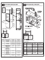
DESIGN INFORMATION
SINGLE OVEN INSTALLATIONS
The single oven may be installed in a cabinet alone or above a warming drawer. The single oven may also
be installed below a countertop or below specified cooktops. See the label on top of the oven for approved
models.
DOUBLE OVEN INSTALLATIONS
A double oven may be installed in a cabinet alone or above a warming drawer. See the label on top of the
oven for approved models.
IMPORTANT: Always refer to individual installation instructions packed with each product for specific
requirements.

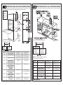
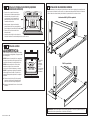
2 A
CUTOUT FOR SINGLE OVENS IN WALL CABINET
NOTE: If the cabinet does not have a front frame and the sides are less than ¾” (1.9 cm) thick, shim
both sides equally to establish the cutout width.
These ovens
are not
approved for
stackable
installations.
Cutout –
observe all
dimensions and
requirements.
Cutout –
observe all
dimensions and
requirements.
2” (5.1 cm) Min.
30.5” (77.5 cm)
30” models
27” (68.58 cm)
27” models
Center Line Center Line
Side-by-Side Installations
Install two ovens in separate cutouts.
Dimension Dimension Description 27” Single Oven 30” Single Oven
A Cabinet Width 27” (68.6 cm) 30” (76.2 cm)
B Cutout Width 25” (63.5 cm) min. 28
1
ø
2
” (72.4 cm) min.
25
1
ø
4
” (64.1 cm) max. 28
5
ø
8
” (72.7 cm) max.
C Cutout Height 27
5
ø
8
” (70.2 cm) min. 27
1
ø
4
” (69.2 cm) min.
28
1
ø
8
” (71.4 cm) max. 27
5
ø
16
” (69.4 cm) max.
D Overlap of Oven Over 1” (2.5 cm)
11
ø
16
” (1.75 cm)
Side Edges of Cutout
E Clearance to 23” (58.4 cm) min. 23” (58.4 cm) min.
Adjacent Corners,
Drawers, Walls, etc.,
When Door Is Open
F Overlap of Oven 1” (2.5 cm) min. 1” (2.5 cm) min.
Top of Cutout (1
1
ø
4
” (3.2 cm) for PT9050)
G Overlap of Oven 1” (2.5 cm) min. 1
1
ø
4
” (3.2 cm)
Bottom of Cutout
H Junction Box Location 8
3
ø
4
” (22.2 cm) max. 9
1
ø
2
” (24.1 cm) max.
right side only right side only
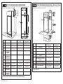
2 B
CUTOUT FOR SINGLE OVENS – UNDER COUNTER
NOTE: These ovens are only approved to be installed under the specific models as labeled on the unit.
Dimension Dimension Description 27” Single Oven 30” Single Oven
A Cabinet Width 25” (63.5 cm) min. 28
1
ø
2
” (72.4 cm) min.
25
1
ø
4
” (64.1 cm) max. 28
5
ø
8
” (72.7 cm) max.
B Cutout Height 27
5
ø
8
” (70.2 cm) min. 27
1
ø
4
” (69.2 cm) min.
28
1
ø
8
” (71.4 cm) max. 27
5
ø
16
” (69.4 cm) max.
C Unit Overlap Top 1” (2.5 cm) 1” (2.5 cm)
(1
1
ø
4
” (3.2 cm) for PT9050)
D Unit Overlap Bottom 1” (2.5 cm) 1
1
ø
4
” (3.2 cm)
E Unit Overlap Side Edges 1” (2.5 cm)
11
ø
16
” (1.75 cm)
F Junction Box Location 8
3
ø
4
” (22.2 cm) max. 9
1
ø
2
” (24.1 cm) max.
right side only right side only
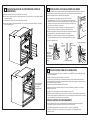
Continue to Section 4.
NOTE: One cooktop may be centered over either oven in
the side-by-side installation.
Cutout – observe
all dimensions and
requirements.
2” (5.1 cm) Min.
30.5” (77.5 cm) 30” models
27” (68.58 cm) 27” models
Center Line Center Line
Side-by-Side Installations
Install two ovens in separate cutouts.
Cooktop
Cutout – observe
all dimensions and
requirements.
H
B
F
G
C
D
A
E
Junction
Box
Location
(junction
box may
be located
in adjacent
cabinet)
22” (55.9
cm) Min. to
Bottom of
Junction
Box
Cutout Depth
23-1/2”
(59.7 cm) Min.
Recommended
Cutout Location
from Floor
32-1/2” (82.6 cm)
Opening
Between Inside
Walls Must be
at Least 28-1/2”
(72.4 cm) Wide
Note: Allow
1/4” (0.64 cm)
clearances
from side
edges of oven
door.

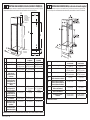
2 C
CUTOUT FOR DOUBLE OVENS
(2 THERMAL OVENS)
NOTE: If the cabinet does not have a front frame and the sides are less than ¾” (1.9 cm) thick, shim
both sides equally to establish the cutout width.
Dim. Description 27” Double Oven 30” Double Oven with
Pedestal
30” Double Oven
without Pedestal
A Cabinet Width 27” (68.6 cm) 30” (76.2 cm) 30” (76.2 cm)
B Cutout Width 25” (63.5 cm) min.
25
1
ø
4
” (64.1 cm) max.
28
1
ø
2
” (72.4 cm) min.
28
5
ø
8
” (72.7 cm) max.
28
1
ø
2
” (72.4 cm) min.
28
5
ø
8
” (72.7 cm) max.
C Cutout Height
49
11
ø
16
” (126.2 cm) min.
50
1
ø
8
” (127.3 cm) max.
51
13
ø
16
” (131.6 cm) min.
51
15
ø
16
” (131.9 cm) max.
50 ¼” (127.64cm)
D Overlap of Oven
Over Side Edges
of Cutout
1” (2.5 cm)
11
ø
16
” (1.75 cm)
11
ø
16
” (1.75 cm)
E
Clearance to
Adjacent Corners,
Drawers, Walls, etc.,
When Door Is Open
23” (58.4 cm) min. 23” (58.4 cm) min. 23” (58.4 cm) min.
F Overlap of Oven
Top of Cutout
1” (2.5 cm) min. 1” (2.5 cm) min.
(1
1
ø
4
” (3.2 cm) for PT9550)
1” (2.5 cm) min.
(1
1
ø
4
” (3.2 cm) for PT9550)
G Overlap of Oven
Bottom of Cutout
1” (2.5 cm) min. 1
1
ø
4
” (3.2 cm) 1
1
ø
4
” (3.2 cm)
H Junction Box
Location
8
3
ø
4
” (22.2 cm) max.
right side only
9
1
ø
2
” (24.1 cm) max.
right side only
9
1
ø
2
” (24.1 cm) max.
right side only
J Height to Bottom
of Junction Box
44” (111.8 cm) 47” (119.4 cm) 47” (119.4 cm)
K Recommended
Cutout Location
from Floor
13
1
ø
4
” (33.7 cm) 12” (30.5 cm) 12” (30.5 cm)
2 D
CUTOUT FOR DOUBLE OVENS (with Upper Microwave Oven)
NOTE: If the cabinet does not have a front frame and the sides are less than ¾” (1.9 cm) thick, shim
both sides equally to establish the cutout width.
Continue to Section 3 for DWO with Pedestal. Otherwise, continue to Section 4.
Continue to Section 4.
H
B
C
K
F
G
D
A
J
E
Junction
Box
Location
(junction
box may
be located
in adjacent
cabinet)
Cutout Depth
23-1/2”
(59.7 cm) Min.
Dim. Description 27” Oven
with Microwave
30” Oven
with Microwave
A Cabinet Width 27” (68.6 cm) 30” (76.2 cm)
B Cutout Width 25” (63.5 cm) min.
25
1
ø
4
” (64.1 cm) max.
28
1
ø
2
” (72.4 cm) min.
28
5
ø
8
” (72.7 cm) max.
C Cutout Height
41
1
ø
8
” (104.5 cm) min.
41
1
ø
4
” (104.8 cm) max.
42
3
ø
16
” (107.2 cm) min.
42
1
ø
4
” (107.3 cm) max.
D Overlap of Oven Over Side Edges
of Cutout
1” (2.5 cm)
11
ø
16
” (1.75 cm)
E Clearance to Adjacent Corners,
Drawers, Walls, etc., When Door
Is Open
23” (58.4 cm) min. 23” (58.4 cm)
F Overlap of Oven Top of Cutout 1” (2.5 cm) min. 1” (2.5 cm) min.
G Overlap of Oven Bottom of Cutout 1” (2.5 cm) min. 1
1
ø
4
” (3.2 cm)
H Junction Box Location 8
3
ø
4
” (22.2 cm) max.
right side only
9
1
ø
2
” (24.1 cm) max.
right side only
31-11044 08-16 GEA

2 F
CUTOUT FOR INSTALLATION OVER A WARMING DRAWER
NOTE: Install the oven only with specific models listed on the label located on top of the oven.
NOTE: Additional clearances between cutouts may be required. Check to be sure the oven supports
above the Warming Drawer location do not obstruct the required interior depth and height.
When installing a Warming Drawer below a single or double oven, a separate 120V, 60 HZ, properly
grounded receptacle must be installed. Refer to installation instructions packed with
the Warming Drawer for specific installation requirements.
2 E
SECURING UPPER MICROWAVE/ADVANTIUM OVEN TO CABINET
For double oven with microwave or Advantium upper ovens. Secure a wooden cleat to side of cabinet
so that the upper oven can be secured to the cleat with provided screws
27” Cabinet requirements
• No shims (or cleats) required when cabinet is in minimum
width condition.
• If cabinet is at maximum width condition, add wood
shims to bring cabinet to minimum condition.
30” Cabinet requirements
• No shims (or cleats) required when cabinet is in minimum
width condition.
• If cabinet is at maximum width condition, fix the wood
cleats as shown in illustration.
Anti-Tip Block Against
Rear Wall Per Warming
Drawer Requirement
2" (5.1 cm)
Min.
Per Warming
Drawer
Requirement
Continue to Section 4
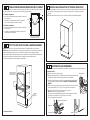
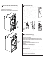
3
PEDESTAL RAIL INSTALLATION (30” DOUBLE OVENS ONLY)
A. Place one pedestal rail on each cabinet runner or centered on opposite side of solid cabinet bottom
flush with side of cabinet opening. Locate each rail so that front of rail is behind front cabinet
opening.
B. Drill pilot holes and attach rails to runner or bottom of cabinet with provided hardware.
6.375”
27.5”
1.5”
3.0”
Cleat locations on 30” cabinet
with maximum cutout condition
Wood Cleats
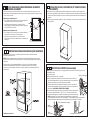
4 A
DOOR REMOVAL (RECOMMENDED)
NOTE: Door removal is not a requirement for installation of the product but is an added convenience.
To remove the door:
A. Open the oven door as far as it will go.
B. Remove hinge bracket from front frame and set aside. The hinge bracket must
be replaced for proper door functionality when door is reinstalled.
C. Push both hinge locks down toward the door frame to the unlocked position.
This may require a flat-blade screwdriver. DO NOT LIFT THE DOOR BY THE
HANDLE!
D. Place hands on both sides of the door and close the oven door to the removal
position (approximately 1”–2” [2.5 cm–5.1 cm] from the closed position).
E. Lift the door up and out until the hinge arms clear the slots.
NOTE: The oven door is very heavy. Be sure
you have a firm grip before lifting the oven door off the hinges. Use caution
once the door is removed. Do not lay the door on its handle.
This could cause dents or scratches.
Hinge Slot
Hinge Arm
Hinge Unlocked Position
Hinge Clears Slot
Hinge Bracket

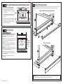
5
ELECTRICAL REQUIREMENTS
WARNING
:
This appliance must be properly grounded.
WARNING
:
To prevent fire or shock, do not use an extension cord with this appliance.
WARNING
:
To prevent shock, remove house fuse or open circuit breaker before
beginning installation.
WARNING
:
Improper connection of aluminum house wiring to copper leads can result
in an electrical hazard or fire. Use only connectors designed for joining copper to aluminum and follow the
manufacturer’s recommended procedure closely.
We recommend you have the electrical wiring and hookup of your appliance connected by a qualified
electrician. After installation, have the electrician show you how to disconnect power from the appliance.
You must use a single-phase, 120/208 VAC or 120/240 VAC, 60 Hertz electrical system. If you connect to
aluminum wiring, properly installed connectors approved for use with aluminum wiring must be used.
Effective January 1, 1996, the National Elec
trical Code requires that new construction (not existing) utilize
a four-conductor connection to an electric oven. When installing an electric oven in new construction,
a mobile home, recreational vehicle or an area where local codes prohibit grounding through the
neutral conductor, refer to the section on four-conductor branch circuit connections.
Check with your local utilities for electrical codes which apply in your area. Failure to wire your oven
according to governing codes could result in a hazardous condition. If there are no local codes, your
oven must be wired and fused to meet the National Electrical Code, NFPA No. 70 – latest edition,
available from the National Fire Protection Association.
5
ELECTRICAL REQUIREMENTS (CONT.)
This appliance must be supplied with the proper voltage and frequency and connected to an individual,
properly grounded branch circuit, protected by a circuit breaker or fuse. See the rating plate located on the
oven frame to determine the rating of the product.
Use the chart below to determine the minimum recommended dedicated circuit protection:
DO NOT shorten the flexible conduit. The conduit strain relief clamp must be securely attached to the
junction box and the flexible conduit must be securely attached to the clamp. If the flexible conduit will not
fit within the clamp, do not install the oven until a clamp of the proper size is obtained.
The 3 power leads supplied with this appliance are suitable for connection to heavier gauge household
wiring. The insulation of these 3 leads is rated for temperatures much higher than the temperature rating of
the household wiring. The current-carrying capacity of the conductor is governed by the wire gauge and the
temperature rating of the insulation around the wire.
Recommended
KW Rating KW Rating Circuit Size
240V 208V (Dedicated)
.: .: $PS
4.9 KW–7.2 KW 4.2 KW–6.2 KW 30 Amp
7.3 KW–9.6 KW 6.3 KW–8.3 KW 40 Amp
9.7 KW–12.0 KW 8.4 KW–10.4 KW 50 Amp
Rating plate is located on the oven side trim.
4 B
SHIPPING SCREWS REMOVAL (FOR 30” DOUBLE WALL
OVEN WITH UPPER MICROWAVE OVEN ONLY)
Shipping screws must be removed as shown in illustration. You will need a 1/4” Nut Driver.
Remove Shipping
Screws From
Both Sides

6
MAKE ELECTRICAL CONNECTIONS
WARNING
:
Switch power off at the service panel and lock the service disconnecting
means to prevent power from being switched on accidentally. When the service disconnecting means
cannot be locked, securely fasten a prominent warning device, such as a tag,
to the service panel.
Place oven on table or platform even with the cutout opening. For a single oven, the platform must
support 200 lbs. (91 kg); and for a double oven, the platform must support 375 lbs. (170 kg). Connect the
flexible conduit to the electrical junction box as shown below*. Position the conduit in such a manner
that it will lie behind the unit in a natural loop when the oven is installed**. You will need to purchase an
appropriate strain relief clamp to complete the connection of the conduit to the junction box.
* Ovens come equipped with a 40” or 54” long conduit. If a longer conduit is desired, there may be one
available for your model. To check availability or order parts, call 1.800.GE.CARES.
** Double Oven with upper microwave oven we recommend install the conduit to side of junction box as
shown in illustration above.
Junction Box
Conduit
Ground
Red
White
Black
Strain Relief Clamp
(not included) Must Be
Used at Junction Box
Place Oven on a
Support to Assist in
Connecting Conduit
Ground
Wire
9
SLIDE OVEN INTO OPENING
A. Loop (do not tie) a 36” (91 cm) string around the conduit before the oven is slid into place. This will
keep the conduit from falling behind the oven.
B. Lift oven into cabinet cutout
using the oven opening as a
grip. Carefully push against oven
front frame. Do not push against
outside edges.
C. As you slide the oven back, pull
the string so that the conduit
will lie on top of the oven in a
natural loop. For double oven
with upper microwave oven pull
conduit so that it sits above left
side of the lower oven (as view
from the front).
D. When you are sure the conduit
is out of the way, slide the oven
¾ way back into the opening.
Remove the string by pulling on
one end of the loop.
Pull Out
on String
Loop While
Pushing
the Oven Into
the Cabinet
7
THREE-CONDUCTOR BRANCH CIRCUIT CONNECTION
NOTE: If residence leads are aluminum conductors, see
WARNING in Section 5, Electrical Requirements.
When connecting to a three-conductor branch circuit, if local
codes permit:
A. Connect the oven ground conductor along with the neutral
(white) lead to the branch circuit neutral (white or gray in
color), using a wire nut.
B. Connect the oven red lead to the branch circuit red lead
and the oven black lead to the branch circuit black lead in
accordance with local codes, using wire nuts.
C. Install proper strain relief clamp.
D. Install junction box cover.
8
FOUR-CONDUCTOR BRANCH CIRCUIT CONNECTION
NOTE: If residence leads are aluminum conductors, see WARNING in Section 5, Electrical Requirements.
When connecting to a four-conductor branch circuit, if local codes permit:
A. Free the neutral (white) lead from being restrained to any other
wires. If necessary, cut the neutral (white) lead and then re-strip
it to expose the proper length of conductor.
B. Attach the appliance grounding lead (green or bare copper) in
accordance with local codes.
C. Connect the oven neutral (white) lead to the branch circuit
neutral (white or gray) in accordance with local codes, using a
wire nut.
D. Connect the oven red lead to the branch circuit red lead and the
oven black lead to the branch circuit black lead in ac cor dance
with local codes, using wire nuts.
E. Install proper strain relief clamp.
F. Install junction box cover.
Ground and
neutral wires (white)
Tape or Crimp
Neutral wire
connection
Black
Red
Branch
circuit
Alternate
knockout
Range
conduit
snaps
into box
Junction Box Cover
Junction Box Cover
White
Black
Red
Branch
circuit
Ground
wires
Alternate
knockout
Range
conduit
snaps
into box

10 A
INSTALL MOUNTING SCREWS (UPPER MICROWAVE OVEN)
• Slide the oven the remaining way into
the opening so that the side flanges and
control panel are against the cabinet
frame. Make sure that the oven is centered
in the opening.
• Open the door, place a turntable tray in the
oven and make sure that the tray in the
unit is level.
• Drill pilot holes through the side flanges.
• Drive the color-matched screws into the
side flanges. It is recommended that the
screws be hand tightened.
10 B
MOUNT THE OVEN
WARNING: Mounting screws
must be used. Failure to do so could result in
the oven falling out of the cabinet, causing
serious injury.
NOTE: During oven mounting step, ensure that no
damage is done to oven gasket which lines the
edge of oven cavity.
NOTE: Before drilling the pilot holes, make sure
the oven is pushed as far back into the opening
as it will go and is centered.
NOTE: If the cabinet is particle board, you must
use #8 x ¾” particle board screws. These may be
purchased at any hardware store.
A. Drill through the mounting holes (top and
bottom) of the side trim for the #8 mounting
screws provided.
B. Secure the oven cabinet with the screws
provided.
Mounting
Hole
Locations
(hole locations
may vary)
11
BOTTOM TRIM INSTALLATION
• With oven installed, attach the bottom trim through its mounting holes in front vertical brace using
two trim screws provided. Bottom trim lip must be placed under flange of bottom air duct.
IMPORTANT: If this unit is ever removed from the cabinet or the oven is ever pulled out for service,
the bottom trim must be removed first or damage to the trim will occur.
The Screws
Must Be a
Minimum of
1/4” (6 mm)
From the
Front of
the Cutout.
SWO’s and DWO installations without pedestal
DWO’s with pedestals
31-11044 08-16 GEA

12
OVEN RACK GUIDE INSTALLATION (IF APPLICABLE)
A. Locate included oven rack guide mounting hardware.
B. Place oven rack guides on cavity wall studs with L bracket towards back of cavity as shown.
C. Install guides using the 8 provided mounting nuts.
D. See Owner’s Manual for detailed rack installation and different rack configuration.
14
FINAL INSTALLATION CHECKLIST
• Check to make sure the circuit breaker is closed (RESET) or the circuit fuses are replaced.
• Be sure power is in service to the building.
• Check that all packing material and tape have been removed. Failure to remove these materials
could result in damage to the appliance once the appliance has been turned on and surfaces have
heated.
• Remove all items from inside the oven.
• Check to be sure that the mounting screws are installed and flush with the side trim
(see Section 10).
• Check that the bottom trim is installed properly (see Section 11).
• Ensure that air duct opening at bottom of unit is free of obstructions.
• Check that oven rack guides (if applicable) are installed correctly and oven racks function smoothly.
OPERATION CHECKLIST
• Turn on the power to the oven (refer to your Owner’s Manual). Verify that the bake and broil units and
all cooking functions operate properly.
• See your Owner’s Manual for the troubleshooting list.
• Be sure all of the oven controls are OFF before leaving the oven.
Oven rack
guide shown
in place.
13
REPLACING THE OVEN DOOR
NOTE: The oven door is heavy. You may need help lifting the door high enough
to slide it into the hinge slots. Do not lift the door by the handle.
A. Lift the oven door by grasping each side.
B. With the door at the same angle as the removal position (approximately
1”–2” [2.5 cm–5.1 cm] from the closed position), seat the notch of the hinge
arm into the bottom edge of the hinge slot. The notch of the hinge arm must
be fully seated into the bottom of the slot.
C. Fully open the door. If the door will not fully open, the indentation is not
seated correctly in the bottom edge of the slot.
D. Push the hinge locks up against the front frame of the oven cavity,
to the locked position.
E. Replace hinge bracket. The hinge bracket must be replaced for proper door
functionality.
F. Close the oven door.
Hinge in
Locked
Position
Notch of Hinge
Securely Fitted
Into Bottom of
Hinge Slot
Bottom
Edge of
Slot
Hinge
Arm
Hinge Notch
Hinge Bracket

ANTES DE COMENZAR
Lea estas instrucciones por completo y con
detenimiento.
•
,03257$17(³ Guarde estas instrucciones
para el uso de inspectores locales.
•
,03257$17(³ Cumpla con todos los
códigos y ordenanzas vigentes.
• Nota al instalador – Asegúrese de dejar estas
instrucciones con el Consumidor.
• Nota al consumidor – Conserve estas
instrucciones para referencia futura.
• Nivel de destreza – La instalación de este
aparato requiere un instalador o electricista
calificados.
• El instalador tiene la responsabilidad de
efectuar una instalación adecuada.
• La garantía no cubre las fallas del producto
provocadas por una instalación incorrecta.
•
Este producto sólo se debe usar en áreas
interiores.
Instrucciones de instalación
Hornos de pared eléctricos empotrados de 27” y 30”
PARA SU SEGURIDAD:
ADVERTENCIA
:
Antes de comenzar la instalación, desconecte la energía
del panel de servicio y bloquee los medios de desconexión para evitar el accionamiento de la energía de manera
accidental. Cuando los medios de desconexión de servicio no pueden bloquearse, coloque sobre
el panel de servicio un dispositivo de advertencia bien visible, como una etiqueta.
El horno debe instalarse bien en un gabinete que se encuentre firmemente sujeto a la estructura de la casa. Si se
coloca peso sobre la puerta del horno, éste puede volcarse y provocar lesiones. Nunca permita que nadie se suba,
siente, pare o cuelgue de la puerta del horno.
Verifique que el revestimiento de las paredes, mostradores y gabinetes ubicados alrededor del horno puedan
soportar el calor (hasta 200°F [93,3°C]) generado por el horno.
¿Preguntas? Llame al 1.800.GE.CARES (1.800.432.2737) o visite GEAppliances.com
En Canadá, llame al 1.800.561.3344 o visite www.GEAppliances.ca.
MATERIALES QUE PUEDE NECESITAR
Caja de conexiones
Tapones de alambre
Abrazadera de alivio de tensión para conducto de 1/2”
36” (91 cm) de cuerda
HERRAMIENTAS NECESARIAS
Broca de perforadora de 1/8” y perforadora
eléctrica o de mano
Destornillador de estrella
Alicates pelacables
Llave de tuercas de 7/16”
Destornillador T20 (soporte de bisagra)
Llave de tuercas de 1/4”
1
QUITE LOS MATERIALES DE EMPAQUE
No quitar los materiales de empaque puede provocar daños al electrodoméstico. Quite todas las partes de
empaque del horno, bandejas y elementos de calentamiento. Quite la película protectora y las etiquetas de
la puerta exterior y panel de control. También, quite los elementos plásticos de los rebordes y panel, toda la
cinta que cubre el horno y los tornillos de envío que fijan el horno a la almohadilla base. Abra la puerta del
horno y quite el material informativo y las bandejas del horno. Quite el reborde inferior de la parte superior del
horno. Se colocará al final del proceso de instalación. El reborde se encuentra envuelto en forma separada y
adherido en la parte superior de la unidad.
Retire los rieles del pedestal de la caja que está aparte y déjelos a
un costado (Hornos con Pared Doble de 30° Únicamente).
2
PREPARE LA ABERTURA
NOTA: Si el gabinete no cuenta con un fondo sólido,
deben instalarse dos abrazaderas o guías para
soportar el peso del horno. Para hornos únicos, las
guías o abrazaderas deben soportar 200 lbs (91 kgs).
Para hornos dobles, las guías o abrazaderas deben
soportar 375 lbs (170 kgs).
NOTA: Si marcas, imperfecciones o la abertura
resultaran visibles sobre el horno instalado, puede
ser necesario agregar cuñas de madera bajo las
guías y el reborde frontal hasta cubrir las marcas
o la abertura.
NOTA: Si el gabinete no cuenta con un armazón
frontal y los lados son menores a un grosor de ¾”
(1,9 cm), coloque cuñas uniformemente sobre ambos
lados para establecer al ancho de la abertura.
ATENCIÓN INSTALADOR: Todos los hornos de pared eléctricos deben contar con cableado de conexión permanente
(cableado directo) dentro de una caja de conexiones aprobada. En estos productos NO se permite la conexión del tipo “enchufe y receptáculo”.
,1)250$&,Ï1'(',6(³2
INSTALACIONES DE HORNO ÚNICO
El horno único puede instalarse solo en un gabinete o sobre un cajón calentador. El horno único también
puede instalarse debajo de un mostrador de encimera o debajo de las estufas especificadas. Vea la
etiqueta de la parte superior del horno para consultar los modelos aprobados.
INSTALACIONES DE HORNO DOBLE
Puede instalarse un horno doble solo en un gabinete o sobre un cajón calentador. Vea la etiqueta de la
parte superior del horno para consultar los modelos aprobados.
IMPORTANTE: Siempre consulte las instrucciones de instalaciones individuales enviadas con cada producto
para requerimientos específicos.

2 B
ABERTURA PARA HORNOS ÚNICOS – BAJO EL MOSTRADOR DE ENCIMERA
NOTA: Estos hornos sólo pueden instalarse bajo los modelos específicos como se indica en la etiqueta
de la unidad.
2 A
ABERTURA PARA HORNOS ÚNICOS EN UN GABIENTE DE PARED
NOTA: Si el gabinete no cuenta con un armazón frontal y los lados son menores a un grosor de 3/4” (1,9 cm),
coloque cuñas uniformemente sobre ambos lados para establecer al ancho de la abertura.
Estos hornos
no están
aprobados
para
instalaciones
apilables.
Abertura – cumpla
con todas las
dimensiones y
requerimientos.
Abertura – cumpla
con todas las
dimensiones y
requerimientos.
2” (5,1 cm) mín.
30.5” (77,5 cm)
modelo 30”
27” (68.58 cm)
modelo 27”
27” (68.58 cm) modelo 27”
Línea central Línea central
Dimensión
Descripción de la dimensión
Horno único de 27” Horno único de 30”
A Ancho del gabinete 27” (68,6 cm) 30” (76,2 cm)
B Ancho de la abertura 25” (63,5 cm) mín. 28
1
ø
2
” (72,4 cm) mín.
25
1
ø
4
” (64,1 cm) máx. 28
5
ø
8
” (72,7 cm) máx.
C Altura de la abertura 27
5
ø
8
” (70,2 cm) mín. 27
1
ø
4
” (69,2 cm) mín.
28
1
ø
8
” (71,4 cm) máx. 27
5
ø
16
” (69,4 cm) máx.
D Superposición del horno 1” (2,5 cm)
11
ø
16
” (1,75 cm)
sobre los costados
laterales de la abertura
E Espacio respecto 23” (58,4 cm) mín. 23” (58,4 cm) mín.
de esquinas adyacentes,
cajones, paredes, etc.,
cuando la puerta
está abierta
F Superposición de la 1” (2,5 cm) mín. 1” (2,5 cm) mín.
parte superior del horno (1
1
ø
4
” (3.2 cm) para PT9050)
de la abertura
G Superposición de la 1” (2,5 cm) mín. 1
1
ø
4
” (3,2 cm)
parte inferior del horno
de la abertura
H Ubicación de la caja 8
3
ø
4
” (22,2 cm) máx. 9
1
ø
2
” (24,1 cm) máx.
de conexiones sólo lado derecho sólo lado derecho
Dimensión
Descripción de la dimensión
Horno único de 27” Horno único de 30”
A Ancho del gabinete 25” (63,5 cm) mín. 28
1
ø
2
” (72,4 cm) mín.
25
1
ø
4
” (64,1 cm) máx. 28
5
ø
8
” (72,7 cm) máx.
B Altura de la abertura 27
5
ø
8
” (70,2 cm) mín. 27
1
ø
4
” (69,2 cm) mín.
28
1
ø
8
” (71,4 cm) máx. 27
5
ø
16
” (69,4 cm) máx.
C Superposición de la 1” (2,5 cm) 1” (2,5 cm)
unidad en parte superior (1
1
ø
4
” (3.2 cm) para PT9050)
D Superposición de la 1” (2,5 cm) 1
1
ø
4
” (3,2 cm)
unidad en parte inferior
E Superposición de la 1” (2,5 cm)
11
ø
16
” (1,75 cm)
unidad en costados laterales
F Ubicación de la caja 8
3
ø
4
” (22,2 cm) máx. 9
1
ø
2
” (24,1 cm) máx.
de conexiones sólo lado derecho sólo lado derecho
Continúe en la sección 4.
NOTA: Una estufa puede centrarse sobre cualquier
horno en la instalación de lado a lado.
Abertura – cumpla
con todas las
dimensiones y
requerimientos.
2” (5,1 cm) Mín.
30,5” (77,5 cm) modelo 30”
Línea central Línea central
Instalaciones lado a lado
Instale dos hornos en aberturas separadas.
Estufa
Abertura – cumpla
con todas las
dimensiones y
requerimientos.
H
B
F
G
C
D
A
E
Ubicanción
de la caja de
conexiones
(la caja de
conexiones
puede hallarse
en un gabinete
adyancente)
22” (55,9 cm)
mín. hasta la
parte inferior
de la caja de
conexiones
Profundidad de la
abertura - 23-1/2”
(59,7 cm) mínimo
Ubicanción
recomendada
de la abertura
desde el piso
32-1/2” (82.6 cm)
La abertura
entre las paredes
nternas debe ser
de por lo menos
28-1/2” (72,4 cm)
Instalaciones lado a lado
Instale dos hornos en aberturas separadas.
Nota: Deje
1/4” (0.64 cm.)
de espacio
desde los
extremos
laterales de
la puerta del
horno.

Continúe a la Sección 3 para conocer detalles del DWO con Pedestal. De otra forma, continúe a la Sección 4.
2 C
ABERTURA PARA HORNOS DOBLES (2 HORNOS TÉRMICOS)
NOTA: Si el gabinete no cuenta con un armazón frontal y los lados son menores a un grosor de 3/4” (1,9 cm),
coloque cuñas uniformemente sobre ambos lados para establecer al ancho de la abertura.
H
B
C
K
F
G
D
A
J
E
Ubicación
de la caja de
conexiones (la caja
de conexiones
puede hallarse
en un gabinete
adyacente
Profundidad de la
abertura 23-1/2”
(59,7 cm) mínimo
Dim.
Descripción
Horno doble de 27” Horno doble de 30”
con pedestal
Horno doble de 30”
sin pedestal
A Ancho del gabinete 27” (68,6 cm) 30” (76,2 cm) 30” (76,2 cm)
B Ancho de la abertura 25” (63,5 cm) min.
25
1
ø
4
” (64,1 cm) max.
28
1
ø
2
” (72,4 cm) min.
28
5
ø
8
” (72,7 cm) max.
28
1
ø
2
” (72,4 cm) min.
28
5
ø
8
” (72.7 cm) max.
C Altura de la abertura 49
11
ø
16
” (126,2 cm) min.
50
1
ø
8
” (127,3 cm) max.
51
13
ø
16
” (131,6 cm) min.
51
15
ø
16
” (131,9 cm) max.
50 ¼” (127,64cm)
D Superposición del
horno sobre los
costados laterales de
la abertura
1” (2,5 cm)
11
ø
16
” (1,75 cm)
11
ø
16
” (1,75 cm)
E Espacio respecto de
esquinas adyacentes,
cajones paredes, etc.,
cuando la puerta está
abierta
23” (58,4 cm) min. 23” (58,4 cm) min. 23” (58,4 cm) min.
F Superposición de la
parte superior del
horno de la abertura
1” (2,5 cm) min. 1” (2,5 cm) min.
(1
1
ø
4
” (3.2 cm) para
PT9550)
1” (2,5 cm) min.
(1
1
ø
4
” (3.2 cm) para
PT9550)
G Superposición de
la parte inferior del
horno de la abertura
1” (2,5 cm) min. 1
1
ø
4
” (3,2 cm) 1
1
ø
4
” (3,2 cm)
H Ubicación de la caja
de conexiones
8
3
ø
4
” (22,2 cm) max.
sólo lado derecho
9
1
ø
2
” (24,1 cm) max.
sólo lado derecho
9
1
ø
2
” (24,1 cm) max.
sólo lado derecho
J Altura hasta la parte
inferior de la caja de
conexiones
44” (111,8 cm) 47” (119,4 cm) 47” (119,4 cm)
K Ubicación
recomendada de la
abertura desde el piso
13
1
ø
4
” (33,7 cm) 12” (30,5 cm) 12” (30,5 cm)
2 D
ABERTURA PARA HORNOS DOBLES (con horno de microondas superior)
NOTA: Si el gabinete no cuenta con un armazón frontal y los lados son menores a un grosor de 3/4”
(1,9 cm), coloque cuñas uniformemente sobre ambos lados para establecer al ancho de la abertura.
Continúe en la sección 4.
Dim.
Descripción
Horno de 27”
con microondas
Horno de 30”
con microondas
A
Ancho del gabinete
27” (68.6 cm) 30” (76.2 cm)
B
Ancho de la abertura
25” (63,5 cm) mín.
25
1
ø
4
” (64,1 cm) máx.
28
1
ø
2
” (72,4 cm) mín.
28
5
ø
8
” (72,7 cm) máx.
C
Altura de la abertura
41
1
ø
8
” (104,5 cm) mín.
41
1
ø
4
” (104,8 cm) máx.
42
3
ø
16
” (107,2 cm) mín.
42
1
ø
4
” (107,3 cm) máx.
D
Superposición del horno sobre los
costados laterales de la abertura
1” (2,5 cm)
11
ø
16
” (1,75 cm)
E
Espacio respecto de esquinas
adyacentes, cajones paredes, etc.,
cuando la puerta está abierta
23” (58,4 cm) mín. 23” (58,4 cm)
F
Superposición de la parte superior
del horno de la abertura
1” (2,5 cm) mín. 1” (2,5 cm) mín.
G
Superposición de la parte inferior
del horno de la abertura
1” (2,5 cm) mín. 1
1
ø
4
” (3,2 cm)
H
Ubicación de la caja de
conexiones
8
3
ø
4
” (22,2 cm) máx.
sólo lado derecho
9
1
ø
2
” (24,1 cm) máx.
sólo lado derecho
31-11044 08-16 GEA

2 F
ABERTURA PARA INSTALACIÓN SOBRE UN CAJÓN CALENTADOR
NOTA: Instale el horno sólo con los modelos específicos listados en la etiqueta ubicada
en la parte superior del horno.
NOTA: Pueden necesitarse espacios adicionales entre las aberturas. Verifique que los soportes
del horno sobre la ubicación de cajón calentador no obstruyan la profundidad y altura interiores
requeridas.
Cuando instale un cajón calentador debajo de un horno único o doble, debe instalarse
un tomacorriente separado de 120V, 60 HZ con adecuada conexión a tierra. Consulte
las instrucciones de instalación enviadas con el cajón calentador para requisitos específicos
de instalación.
Continúe en la sección 4.
3
INSTALACIÓN DEL RIEL CON PEDESTAL (30” HORNOS DOBLES
ÚNICAMENTE)
A. Coloque un riel con pedestal en cada rodadura del gabinete o centrado en el lado opuesto de la
parte inferior del gabinete sólido nivelado con el lateral de la abertura del gabinete. Ubique cada riel
de modo que la parte frontal de los mismos se encuentre detrás del lado frontal de la abertura del
gabinete.
B. Realice agujeros de prueba y adjunte los rieles a la rodadura o a la parte inferior del gabinete con el
equipo provisto.
2 E
CÓMO ASEGURAR EL HORNO MICROONDAS/ ADVANTIUM
SUPERIOR AL GABINETE
Para hornos dobles como hornos superiores con microondas o Advantium. Asegure un taco de
Madera sobre el costado del gabinete, de modo que el horno superior pueda ser asegurado al taco
con los tornillos provistos.
Requisitos para el gabinete de 27”
• No se requiere el uso de cuñas (o tacos) cuando el gabinete
se encuentre en la condición de ancho mínimo.
• Si el gabinete se encuentra en la condición de ancho
máximo, agregue cuñas de madera para llevar el gabinete a
la condición de ancho mínimo.
Requisitos para el gabinete de 30”
• No se requiere el uso de cuñas (o tacos) cuando el gabinete
se encuentre en la condición de ancho mínimo.
• Si el gabinete se encuentra en la condición de ancho
máximo, repare los tacos de madera como se muestra en la
ilustración.
6.375”
27.5”
1.5”
3.0”
Ubicaciones de los tacos en un gabinete de
30” con la condición de abertura máxima
Tacos de madera
4 A
REMOCIÓN DE LA PUERTA (recomendada)
NOTA: La remoción de la puerta no es un requerimiento de la instalación del producto, pero es una
comodidad adicional.
Para quitar la puerta:
A. Abra la puerta del horno en su totalidad.
B. Retire el soporte de la bisagra de la estructura frontal y déjelo a un lado. El
soporte de la bisagra debe ser colocado nuevamente para un funcionamiento
apropiado de la puerta cuando está última sea reinstalada.
C. Presione ambas trabas de la bisagra hacia abajo en dirección del marco de
la puerta hasta destrabarlas. Para esto puede hacer falta un destornillador de
lados planos. ¡NO LEVANTE LA PUERTA DE LA MANIJA!
D. Coloque las manos sobre ambos lados y cierre la puerta del horno hasta la posición
de remoción (aproximadamente 1”–2” [2,5 cm–5,1 cm] de la posición de cierre).
E. Levante la puerta hasta que los brazos de la bisagra hayan salido de las ranuras.
NOTA: La puerta del horno es muy pesada. Asegúrese de tener un agarre firme
antes de levantar la puerta del horno de sus bisagras. Tenga cuidado una vez que haya quitado la
puerta. No deposite la puerta sobre la manija. Esto puede provocar abolladuras o rayones.
Ranura
de la bisagra
Brazo
de la bisagra
Posición destrabada de la bisagra
La bisagra sale de la ranura
Soporte de la Bisagra

5
REQUISITOS ELÉCTRICOS
ADVERTENCIA
:
Este aparato debe contar con una adecuada conexión a tierra.
ADVERTENCIA
:
Para prevenir un incendio o descarga eléctrica, no utilice un cable
de extensión con este aparato.
ADVERTENCIA
:
Para prevenir una descarga eléctrica, quite el fusible o abra el
interruptor de circuitos antes de comenzar la instalación.
ADVERTENCIA
:
Una conexión inadecuada de cableado doméstico de aluminio con
cables de cobre puede generar un peligro eléctrico o un incendio. Sólo use conectores diseñados para unir
cobre con aluminio y siga al pie de la letra el procedimiento recomendado del fabricante.
Recomendamos que un electricista calificado conecte el cableado eléctrico de su aparato. Después
de la instalación, solicite al electricista que le indique cómo desconectar la energía del aparato.
Usted debe usar un sistema eléctrico de fase única de 120/208 VAC o 120/240 VAC de 60 hercios. Si tiene
una conexión con cableado de aluminio, deben utilizarse conectores adecuadamente instalados para
utilizar con cableado de aluminio.
Vigente desde el 1 de enero de 1996, el Código Eléctrico Nacional requiere que las nuevas construcciones
(no existentes) utilicen una conexión de cuatro conductores a un horno eléctrico. Cuando instale un horno
eléctrico en una construcción nueva, una casa rodante, un vehículo recreativo o un área donde los códigos
locales prohíben la conexión a tierra a través de un conductor neutral, consulte la sección sobre conexiones
en circuito derivado de cuatro conductores.
Consulte a las empresas de servicio público sobre los códigos eléctricos que se aplican en su área. No
realizar el cableado de su horno de acuerdo con los códigos vigentes puede provocar una situación
peligrosa. Si no existen códigos locales, el cableado y fusibles de su horno deben cumplir con el Código
Eléctrico Nacional, NFPA Nº 70, última edición, disponible en National Fire Protection Association (Asociación
Nacional de Protección contra Incendios).
5
REQUISITOS ELÉCTRICOS (CONT.)
Este aparato debe recibir el voltaje y frecuencia adecuados, y debe conectarse a un circuito derivado
individual con adecuada conexión a tierra, protegido por un interruptor de circuitos o fusible. Ver la placa de
clasificación ubicada en el armazón del horno para determinar la clasificación del producto.
Utilice la tabla de abajo para determinar la protección de circuito dedicado mínima recomendada:
NO acorte el conducto flexible. La abrazadera del alivio de tensión del conducto debe estar bien sujeta a la
caja de conexiones y el conducto flexible debe estar bien sujeto a la abrazadera. Si el conducto flexible no
entra dentro de la abrazadera, no instale el horno hasta obtener una abrazadera del tamaño adecuado.
Los 3 cables de energía suministrados con este aparato son adecuados para conexiones con cableados
domésticos de calibre mayores. La aislación de estos 3 cables está clasificada a temperaturas mucho más
elevadas que la clasificación del cableado doméstico. La capacidad
de transmitir corriente del conductor está determinada por el calibre del cable y la clasificación
de temperatura de la aislación alrededor del cable.
Clasificación Tamaño de circuito
de KW Clasificación de KW recomendado
240V 208V (dedicado)
.: .: $PS
.:².: .:².: $PS
.:².: .:².: $PS
.:².: .:².: $PS
La placa de clasificación se encuentra en el reborde
lateral del horno.
4 B
RETIRO DE LOS TORNILLOS DE EMBALAJE (PARA HORNO
DE PARED DOBLE CON HORNO MICROONDAS SUPERIOR
ÚNICAMENTE)
Los tornillos de embalaje deben ser retirados como se muestra en la ilustración. Necesitará un
destornillador de ¼”.
Retire los Tornillos
de Embalaje a
Ambos Lados.

6
REALICE LAS CONEXIONES ELÉCTRICAS
ADVERTENCIA
:
Desconecte la energía del panel de servicio y bloquee los medios
de desconexión para evitar el accionamiento de la energía de manera accidental. Cuando los medios
de desconexión de servicio no pueden bloquearse, coloque sobre el panel de servicio un dispositivo de
advertencia bien visible, como una etiqueta.
Coloque el horno sobre una mesa o plataforma en forma nivelada con la abertura. Para un horno único,
la plataforma debe soportar 200 lbs. (91 kg); para un horno doble, la plataforma debe soportar 375 lbs.
(170 kg). Conecte el conducto flexible a la caja de conexiones eléctrica como se indica abajo*. Posicione
el conducto de modo tal que se apoye detrás de la unidad en un círculo natural cuando el horno sea
instalado**. Tendrá que comprar una abrazadera para alivio de tensión apropiada para completar la
conexión del conducto a la caja de conexiones.
* Los hornos vienen equipados con un conducto de 40” o 54” de longitud. Si desea un conducto más largo, puede
haber uno disponible para su modelo. Para verificar la disponibilidad o solicitar piezas, llame al 1.800.GE.CARES.
** Para el Horno Doble con horno microondas superior recomendamos la instalación del conducto al costado de la caja
de empalmes, como se muestra en la ilustración anterior.
Caja de conexiones
Conducto
Tierra
Rojo
Blanco
Negro
La abrazadera del alivio
de tensión (no incluido)
debe usarse en la caja de
conexiones
Coloque el horno
en un soporte para
ayudar a la conexión del
conducto
Cable
a tierra
9
DESLICE EL HORNO DENTRO DE LA ABERTURA
A. Enrosque (no ate) un hilo de 36” (91 cm) alrededor del conducto antes de deslizar el horno en su
lugar. Esto no permitirá que el conducto caiga detrás del horno.
B. Levante el horno dentro de la
abertura del gabinete utilizando
el horno abierto como agarre.
Con cuidado empuje contra
el armazón frontal del horno.
No presione sobre los bordes
externos.
C. A medida que desliza el horno
hacia atrás, jale del hilo para
que el conducto quede sobre
el horno con un lazo natural.
Con hornos dobles con horno
microondas en la parte superior,
jale el conducto, de modo que
se apoye sobre el lado izquierdo
del horno inferior (como se ve
desde el frente).
D. Cuando se asegure de que el
conducto no esté en el camino,
deslice el horno ¾ hacia atrás
dentro de la abertura. Quite el hilo
jalando de un extremo del lazo.
Jale del
lazo de hilo
mientras
empuja el
horno dentro
del gabinete
7
CONEXIÓN DE CIRCUITO DERIVADO DE TRES CONDUCTORES
NOTA: Si los cables del hogar poseen conductores de aluminio, ver la ADVERTENCIA de la sección 5,
Requisitos eléctricos.
Cuando conecte un circuito derivado de tres conductores, si lo
permiten los códigos locales:
A. Conecte el conductor de conexión a tierra junto con el cable
neutro (blanco) al neutro del circuito de empalmes (de color blanco
o gris), usando una tuerca para cables.
B. Conecte el cable rojo del horno al cable rojo del circuito derivado
y el cable negro del horno al cable negro del circuito derivado de
acuerdo con los códigos locales, utilizando tapones de alambre.
C. Instale una abrazadera adecuada de alivio de tensión.
D. Instale la tapa de la caja de conexiones.
8
CONEXIÓN DE CIRCUITO DERIVADO DE CUATRO
CONDUCTORES
NOTA: Si los cables domésticos son conductores de aluminio, ver la ADVERTENCIA de la sección 5,
Requisitos eléctricos.
Cuando conecte un circuito derivado de cuatro conductores, si lo permiten los códigos locales:
A. Evite que el conductor neutro (blanco) quede enredado con
cualquier otro cable. De ser necesario, corte el conductor
neutro (blanco) y luego vuelva a pelar el mismo, a fin de
exponer la longitud adecuada del conductor.
B. Conecte el cable a tierra del aparato (verde o cobre) de
acuerdo con los códigos locales.
C. Conecte el cable neutral (blanco) del horno con el neutral
de circuito derivado (blanco o gris) de acuerdo con códigos
locales, utilizando un tapón de alambre.
D. Conecte el cable rojo del horno al cable rojo del circuito
derivado y el cable negro del horno al cable negro del circuito
derivado de acuerdo con los códigos locales, utilizando
tapones de alambre.
E. Instale una abrazadera adecuada de alivio de tensión.
F. Instale la tapa de la caja de conexiones.
Cables a tierra
y neutrales (blanco)
Encinte o Prense
Cable neutral
conexión
Negro
Rojo
Circuito
ramificado
Agujero
ciego
alternativo
El tubo de
la estufa
se ajusta
en la caja
Tapa de la caja de conexiones
Tapa de la caja de conexiones
Blanco
Negro
Rojo
Circuito
ramificado
Cables a
tierra
Agujero ciego
alternativo
El tubo de
la estufa
se ajusta
en la caja

IMPORTANTE: Si esta unidad alguna vez se quita del gabinete o si el horno se quita de servicio, el
reborde inferior debe quitarse antes o el reborde sufrirá daños.
11
INSTALACIÓN DEL REBORDE INFERIOR
• Una vez instalado el horno, adjunte el borde inferior a través de sus agujeros de montaje frente al
soporte vertical, utilizando los dos tornillos con cabeza recortada provistos. El labio de la cubierta
inferior deberá ser ubicado debajo de la brida de la parte inferior del conducto de aire.
Instalaciones SWO y DWO sin pedestal
DWO sin pedestales
10 B
INSTALE EL HORNO
ADVERTENCIA
:
Deben utilizarse tornillos de montaje. Si no lo hace,
el horno puede caer del gabinete, lo que provocaría
una lesión grave.
NOTA: Durante el montaje del horno, asegúrese
de que no haya daños sobre la junta del horno,
que aliña el extremo de la cavidad del horno
NOTA: Antes de perforar los orificios piloto,
asegúrese de que el horno se encuentre
en la posición final de la abertura y centrado.
NOTA: Si el gabinete es de placa de partículas,
deben utilizarse tornillos #8 x ¾” para dicho
material. Éstos pueden adquirirse en cualquier
ferretería.
A. Perfore a través de los orificios de montaje
(superiores e inferiores) del reborde lateral
para los tornillos de montaje #8 provistos.
B. Asegure el gabinete del horno con los tornillos
provistos.
Los tornillos
deben
hallarse a
un mínimo
de ¼”
(6 mm) desde
el frente de
la abertura.
10 A
INSTALE LOS TORNILLOS DE MONTAJE (HORNO
MICROONDAS SUPERIOR)
• Deslice el horno por la distancia que
falta dentro de la abertura para que las
bridas laterales y el panel de control
se encuentren contra el armazón del
gabinete. Verifique que el horno esté
centrado en la abertura.
• Abra la puerta, coloque una bandeja
giratoria dentro del horno y asegúrese de
que la bandeja de la unidad esté nivelada.
• Perfore orificios piloto a través de las
bridas laterales.
• Introduzca los tornillos de color dentro de
las bridas laterales. Se recomienda ajustar los tornillos a mano.
31-11044 08-16 GEA

14
LISTA DE CONTROL FINAL DE LA INSTALACIÓN
• Verifique que el interruptor de circuitos se encuentre cerrado (RESET) o que los fusibles del circuito
se hayan reemplazado.
• Asegúrese de que haya suministro eléctrico en el edificio.
• Controle que se haya quitado todo el material de empaque y la cinta adhesiva. No quitar estos
materiales puede provocar daños al electrodoméstico una vez que el aparato se haya encendido y
las superficies se hayan calentado.
• Quite todos los elementos ubicados dentro del horno.
• Asegúrese de que los tornillos de montaje se encuentren instalados y nivelados con el reborde
lateral (ver sección 10).
• Verifique que el reborde inferior esté bien instalado (ver sección 11).
• Asegúrese de que la abertura inferior del conducto de aire de la unidad esté libre de obstrucciones.
• Controle que las guías de los estantes del horno (si corresponde) estén instaladas de forma correcta
y que los estantes del horno funcionen de forma fluida.
LISTA DE CONTROL DE FUNCIONAMIENTO
• Accione la energía del horno (consulte el Manual del propietario). Verifique que las unidades
de horneado y asado y que todas las funciones de cocción operen bien.
• Ver el Manual del propietario para la lista de detección y solución de problemas.
• Asegúrese de que todos los controles del horno se encuentren en OFF (apagado) antes
de dejar el horno.
12
GUÍA DE INSTALACIÓN DE LA ESTANTERÍA DEL HORNO (SI
CORRESPONDE)
A. Ubique el equipo de montaje de la guía del horno incluida.
B. Posicione el conducto de modo tal que se apoye detrás de la unidad en un círculo natural cuando el
horno sea instalado.
C. Instale las guías usando las 8 tuercas de montaje provistas.
D. Para una instalación de estantes detallada y una configuración de estantes diferente, consulte el
Manual del Propietario.
Imagen de la guía
de la estantería
en su lugar
correspondiente.
13
CÓMO VOLVER A COLOCAR LA PUERTA DEL HORNO
NOTA: La puerta del horno es pesada. Puede necesitar ayuda para levantar la puerta lo suficiente
como para deslizarla dentro de las ranuras de la bisagra. No levante la puerta de la manija.
A. Levante la puerta del horno tomándola de ambos lados.
B. Con la puerta en el mismo ángulo de la posición de remoción
(aproximadamente 1”–2” [2,5 cm–5,1 cm] desde la posición de cerrado),
introduzca la muesca del brazo de la bisagra dentro del extremo inferior de
la ranura de la bisagra. La ranura del brazo de la bisagra debe estar bien
colocada en la parte inferior de la ranura.
C. Abra la puerta por completo. Si la puerta no se abre por completo, la
muesca no está bien colocada en el extremo inferior de la ranura.
D. Presione las trabas de la bisagra hacia arriba contra el armazón frontal de
la cavidad del horno, hasta alcanzar la posición de trabado.
E. Reemplace el soporte de la bisagra. El soporte de la bisagra debe ser
colocado nuevamente para un funcionamiento apropiado de la puerta.
F. Cierre la puerta del horno.
Bisagra en
la posición
de trabado
Ranura de la
bisagra bien
colocada en la
parte inferior de
la ranura de la
bisagra
Lado
inferior de
la ranura
Brazo
de la bisagra
Ranura de la bisagra
Soporte de la Bisagra
-
 1
1
-
 2
2
-
 3
3
-
 4
4
-
 5
5
-
 6
6
-
 7
7
-
 8
8
-
 9
9
-
 10
10
-
 11
11
-
 12
12
-
 13
13
-
 14
14
-
 15
15
-
 16
16


Ask a question and I''ll find the answer in the document
Finding information in a document is now easier with AI
in other languages
- español: GE JT3800DHBB Guía de instalación
Related papers
-
Yes CT9570SLSS Installation guide
-
GE CTD90FP2M1S1 Installation guide
-
GE Appliances JK3800SHSS Installation guide
-
GE Appliances ZET1SHSS Installation guide
-
GE Appliances JTS5000FNDS User manual
-
GE Appliances ZET1SHSS Installation guide
-
GE ZEK938SF5SS Installation guide
-
GE JKP48WF1WW Installation guide
-
-
GE CK7000SHSS Installation guide
Other documents
-
GE Monogram ZET2FLSS Installation guide
-
-
Yes CTD90FP2MS1 Installation guide
-
-
 GE Monogram ZET1SHSS DL c3d43127eaf03e7a0c3bc9a37494
-
Yes CTS70DP2NS1 Installation guide
-
GE Profile PK7000FMDS Installation guide
-
Kenmore 91147704200 Installation guide
-
Yes PK7500DFBB Installation guide
-
Cafe Appliances CTD90FP4NW2 User manual
