3
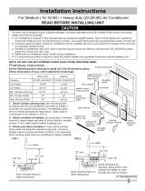
Installation Instructions
Remove Air Conditioner from Cabinet
NOTE: Remove any packaging material from cabinet exterior.
1
1. Pull down on front grille from upper edge. Lift front grille upwards and place to one side. (See FIG.1)
2. Remove filter. To remove, grasp in the middle on each side. Bow filter out to detach top edge from tabs. Once top
is free, lift filter up and out.
3. Locate the four Front Panel screws and remove. These screws will be needed to re-install the Front Panel later
(See FIG.2)
4. Push metal cabinet side inward to release plastic tabs on each side of Front Panel (see Fig. 3).
5. Rotate Front Panel up until top tabs are free. Pull panel straight out. When pulling out, front panel will also pull free
from vent control lever. Depress latch on electronics plug (on some models) to disconnect.
6. Remove Front Panel from unit (see Fig. 4).
7. Remove shipping screws from top of unit and also on both sides by the base if installed. (See FIG.5)
8. With the aid of an assistant, hold the cabinet while pulling on the base pan handle (see FIG. 4), and carefully
remove the air conditioner from cabinet.
9. Add two foam inserts to holes in top of cabinet where shipping screws were removed from. (See FIG.6)
10. Except 22,000BTU model, other heavy duty models (24,000~28,500BTU) come with internal shipping packaging.
THIS PACKAGING AND PLASTIC TIES MUST BE REMOVED PRIOR TO INSTALLING THE AIR CONDITIONER
BACK INTO THE CABINET. (See FIG.7)
11. Remove plastic wrapping from all points on power cord.
Install Top Angle Rail and Side Retainers
2
1. Remove adhesive strip coating from foam gasket. Attach adhesive side of gasket to bottom of top angle rail. Insert 4
screws from inside of cabinet and secure to top angle rail.
2. From inside of cabinet insert 3 screws to attach each side retainer as shown
in Fig. 8. Attach side retainers with flat side against cabinet and angled edge toward
rear of cabinet.
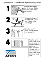
Assemble Window Filler Panels
3
1. Place cabinet on floor, a bench, or a table.
2. Slide "I" section at end of window filler panel into side retainer on each side of the
cabinet (see FIG. 9 and FIG.10).
3. On each side of cabinet, insert top and bottom legs of window filler panel
frame into channel in the top and bottom angle rails.
4. Insert a 7/16" locking screw and flat washer into hole on top leg of each window filler panel (see section 6). Do not
totally tighten. Allow leg to slide freely. Screws will be tightened after Section 6.
Window Mounting
FIG.1
FIG.2
FIG.6
FIG.3
FIG.4
base pan handle
Shipping Packaging
Plastic tie
Front Grille
FIG.7
Foam Gasket
Top angle rail
FIG.8
FIG.5
shipping
screws