Lifebreath Stereo Amplifier 155MAX User manual
- Category
- Air filters
- Type
- User manual

®
CLEAN • FRESH • AIR
* LEAVE FOR HOMEOWNER
NOTE: Due to ongoing research and product development, specifications,
ratings and dimensions are subject to change without notice.
TI-84R-NE
0112
Installing Contractor
Telephone / Contact
Serial Number
Installation Date Model
TO BE COMPLETED BY CONTRACTOR AFTER INSTALLATION
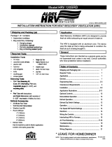
OPERATION AND
INSTALLATION MANUAL
Contains
ControlAir 15
For Models:
95MAX
155MAX
200MAX
MAXTOP
195DCS
300DCS
200ERV
200ERVD
CAUTION
Before installation, careful consideration must be given to
how this system will operate if connected to any other piece
of mechanical equipment, i.e. a forced air furnace or air
handler, operating at a higher static. After installation, the
compatibility of the two pieces of equipment must be
confirmed by measuring the airflow’s of the Heat Recovery
Ventilator (HRV) or Energy Recovery Ventilator (ERV) by
using the balancing procedure found in this manual.
It is always important to assess how the operation of any
HRV/ERV may interact with vented combustion equipment
(ie. Gas Furnaces, Oil Furnaces, Wood Stoves, etc.).
NEVER install a ventilator in a situation where its normal
operation, lack of operation or partial failure may result
in the backdrafting or improper functioning of vented
combustion equipment!!!
IMPORTANT - PLEASE READ THIS
MANUAL BEFORE INSTALLING UNIT

2
Table of Contents
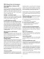
Introduction...................
......
.......................................... 2
Warranty ....................................................................... 2
ERV Questions & Answers .......................................... 3
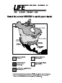
Climate Map ................................................................. 4
Technical Data - Model 95MAX ................................... 5
Technical Data - Model 155MAX ................................. 6
Technical Data - Model 200MAX ................................. 7
Technical Data - Model MAXTOP................................ 8
Technical Data - Model 195DCS ................................. 9
Technical Data - Model 300DCS ............................... 10
Technical Data - Model 200ERV ................................ 11
Technical Data - Model 200ERVD ............................. 12
Function and Control
Operation of the ControlAir 15 ....................................13
Glossary of Terms
....................................................
..13
To Select Mode of Operation.......................................14
Optional Remote Controls ......................................... 15
Using the Dehumidistat............................................ 16
Schematic Diagram - Model 95MAX ....................... 17
m
Installation
Installation
............................................................... 18
• Location
• Mounting the HRV/ERV
• Electrical
• Installing the Drain Line and "P" Trap
Installing Air Ducts .................................................. 19
• Outside Weatherhoods
• Locating the Weatherhoods
•
Installing Ducting from Weatherhoods to the HRV/ERV
• Warmside Ducting
Supply Air Ducting ..................................................... 20
Stale Air Exhaust System .......................................... 20
Dampers and Grilles .................................................. 20
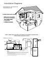
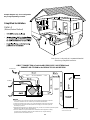
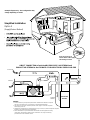
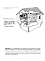
Installation Diagrams .......................................... 21 - 24
Air Flow Balancing ..................................................... 25
Maintenance
Maintenance Routine For HRV .................................. 27
Maintenance Routine For ERV .................................. 28
Troubleshooting.......................................................... 29
Wiring Diagram .......................................................... 31
INTRODUCTION
HRV - Aluminum Core
A Heat Recovery Ventilator (HRV) is designed to
provide fresh air into a building while exhausting an
equal amount of stale air. During the winter
months, the incoming cold fresh air is warmed by
utilizing the heat recovered from the stale air
before it is exhausted to the outdoors. During
summer months when the indoor space is air
conditioned, the Heat Recovery Ventilator will help
in cooling the incoming fresh air with the stale air
that is being exhausted.
ERV - Enthalpic Paper Core
An Energy Recovery Ventilator (ERV) is designed
to provide fresh air into a building while exhausting
an equal amount of stale air. An ERV is designed
for use in warm humid areas with heavy air
conditioning use. The ERV will transfer both
sensible and latent heat from the incoming fresh air
to the outgoing stale air thereby reducing the load
(due to ventilation) on the air conditioning system.
ERVs are not suitable for climates where the
temperature drops below -4˚C (25˚F).
WARRANTY
All Heat Recovery Ventilators carry a Lifetime
Warranty on the heat recovery core and a 5 (five)
year replacement parts warranty.
All Energy Recovery Ventilators carry a 5 (five) year
warranty on the energy recovery core and a 5 (five)
year replacement parts warranty.
During the warranty period, if any core experiences a
failure or perforation caused by normal use while
owned by the original purchaser, a replacement core
(FOB our plant) will be supplied at no expense.
®

3
ERV Questions & Answers
What is the difference between an HRV
and an ERV?
The core in an HRV (Heat Recovery Ventilator)
transfers heat from one air stream to the other. This is
called sensible heat. The term ERV (Energy Recovery
Ventilator) is usually used to describe a unit with an
enthalpic core that transfers moisture as well as heat
from one air stream to the other. This (moisture
transfer) is called latent heat.
Enthalpic - what does it mean?
Enthalpy is the term used to describe the energy
content of air. This energy is a combination of the
sensible and latent heat. Therefore, a core which
transfers energy is called an enthalpic core.
Is an ERV better than an HRV?
NOT NECESSARILY!! In cold climates such as most
of North America, an HRV works better than an ERV.
This is because the air inside the home during the
winter months will be more humid than the outside air.
An ERV would transfer the latent heat (humidity) from
the exhaust air back into the incoming airstream. This
will aggravate moisture problems in the home and
encourage the growth of mold and mildew. If the air in
the home is too dry for comfort, an ERV will not help. A
humidifier should be used to increase the humidity to
a comfortable level.
Where do you use an ERV instead
of an HRV?
An ERV is recommended for warm, humid areas with
heavy air conditioning use. As there is no defrost in an
ERV it is not recommended for areas where the
temperature drops below -4˚C (25˚F).
Why transfer moisture in the summer
(cooling season)?
The enthalpic core will allow moisture to be transferred
from a humid air flow to a dry air flow. This property is
useful in the cooling season if an air conditioning
system is used to lower the indoor humidity. You will
then have dry, cool air in the exhaust of the ERV, and
warm humid air in the supply stream. With these
conditions, the ERV will be able to transfer the
moisture and heat of the supply air to the exhaust air.
In this way, the ERV will supply to the home air which
is cooler and drier than outside. Remember that an
ERV is not a dehumidifier, and on its own will not take
moisture out of the air.
So why use an ERV?
A properly operating air conditioner will not only lower
the temperature in your house, but will also lower the
humidity level. This prevents an uncomfortable cold
and damp situation. In fact, about 2/3 of the energy
used by the air conditioner system is to remove
moisture. Therefore, when ventilating in the summer,
less moisture brought into the home means less work
for the air conditioner, and energy savings for you.
During the winter, an ERV recovers some humidity
from the exhaust air, reducing the need for humidification
,
if the required ventilation rate would make the home
too dry.
What's the difference between this type of
core and a rotary type?
Here's a list of characteristics of the fixed plate core.
1. No rotating parts, so maintenance is easy and the
unit lasts a long time.
2. It is very flexible in terms of installation.
3. The core can easily be changed.
4. Because the supply and exhaust air streams are
completely separate, there is very little cross
leakage of any dust or germs.
Can the core become clogged with dust?
Because the surface of the core is a turbulent flow
area, dust sticks to it easily; however, because the
inside of the element is a laminar flow area, virtually no
dust sticks to it.
What is the maintenance?
About once a year you should use a vacuum cleaner
to remove the dust from the core's surface. DO NOT
WASH WITH WATER!!
Is an air filter needed?
To prevent clogging of the core, an air filter should
always be installed on the supply and exhaust sides of
the core.
How much ventilation do I need?
During seasons when your windows and doors are
closed, the ERV should operate continuously when
the dwelling is occupied, and either continuously or
intermittently when not occupied.
For most installations the ERV will normally be set to
operate continuously on low speed with the option of
going to high speed as the need arises. For example;
if you are entertaining and there is a large number of
people present (some may be smoking), the unit
should be switched to high speed.
Your ERV may be equipped with automatic or manual
switches, but all ERVs will have a manual speed
control override.

4

5
Removably
Heat Recovery
Core
Drain Pan
Drain spout
FRONT TOP
knockout for
side mounting of
EXHAUST return port
6" round collar
converted to oval
minimum
18 inches (459 mm)
required for
service access
Threaded
inserts (4)
at corners
SUPPLY
Fresh air
from outside
5" round collar
SUPPLY
Fresh air
to building
6" round
(conv. to oval)
collar
EXHAUST
Stale Air
to outside
5" round collar
EXHAUST
Return air
from building
Choice of port location
Knockouts on top and
side of unit (use 1 only)
6" round (conv. to oval)
collar supplied
DIMENSIONS 95MAX
inches (mm)
18.5"
(470 mm)
18.5"
(470 mm)
16"
(406 mm)
SIDE
Hanging
straps (4)
24.5"
(622 mm)
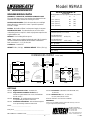
Model 95MAX
ENGINEERING DATA
THERMALLY CONDUCTIVE, PATENTED ALUMINUM CORE
The cross-flow heat recovery core transfers heat between the two
airstreams. It is easily removed for cleaning or service.
MOTORS AND BLOWERS
- Each air stream has one centrifugal
blower driven by a common PSC motor. 5 speed fan operation.
120 VAC, .8 Amps.
FILTERS
- Washable air filters in exhaust and supply air streams.
MOUNTING THE HRV
- Four threaded inserts at corners of the
cabinet designed to accept PVC reinforced polyester straps that are
supplied with the unit.
DEFROST
- Recirculating defrost system.
CASE
- Twenty gauge prepainted galvanized steel (G60) for superior
corrosion resistance. Insulated to prevent exterior condensation.
Drain connections 2 - 1/2" (12 mm) OD.
CONTROLS
- ControlAir 15
WEIGHT 52 lbs. (23.6 kg) SHIPPING WEIGHT 56 lbs. (25.4
kg)
OPTIONS
99-104 Digital Electronic Timer - 20/40/60 min.
99-105 Programmable Ventilation Control
(PVC)
includes Programmable Time Clock, Dehumidistat
and Air Sentry™
99-109 Air Sentry™ Air Quality Monitor designed to
accept remotely mounted Control Pad
99-250 Ventilation Dehumidistat - Dehumidistat designed
to accept remotely mounted Control Pad
99-163 Duct Heater
w/ Electronic SCR Thermostat, 1 Kw,
6” (150 mm)
99-186 Weatherhoods, Two - 5” (125 mm)
c/w 1/4” (6 mm) mesh screen
All units conform to CSA and UL standards.
WARRANTY
Units carry a LIFETIME warranty on the heat recovery core and
a 5 year replacement parts warranty.
DATE: __________________________
PROJECT: ________________________________________
MECHANICAL CONTRACTOR: ________________________________
TI-113-NE
0103
511 McCormick Blvd.
London, Ontario
N5W 4C8
Ph: (519) 457-1904
Fx: (519) 457-1676
Email: [email protected]
Website: www.lifebreath.com
PERFORMANCE
HVI CERTIFIED
Net supply airflow in cfm (L/s) against external static pressure
E.S.P cfm L/s
@ 0.1” (25 Pa) 89 (42)
@ 0.2” (50 Pa) 78 (37)
@ 0.3” (75 Pa) 64 (30)
@ 0.4” (100 Pa) 36 (17)
Maximum Temperature Recovery 74%
Sensible Effectiveness
@ 64 cfm (30 L/s)
(CSA C439M)
80%
Sensible Efficiency
@ 64 cfm (30 L/s) 32˚F (0˚C) 75%
Sensible Efficiency
@ 64 cfm (30 L/s) -13˚F (-25˚C) 75%
VAC @ 60HZ 120
WATTS / Low speed 35
WATTS / High speed 136
Amp rating 0.8

6
DATE: __________________________
PROJECT: __________________________________________
MECHANICAL CONTRACTOR: _____________________________
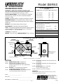
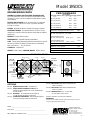
Model 155MAX
ENGINEERING DATA
THERMALLY CONDUCTIVE, PATENTED ALUMINUM CORE
The cross-flow heat recovery core transfers heat between the two
airstreams. It is easily removed for cleaning or service.
MOTORS AND BLOWERS -
Each air stream has one centrifugal
blower driven by a common PSC motor. 5 speed fan operation.
120 VAC, 1.0 Amps.
FILTERS - Washable air filters in exhaust and supply air streams.
MOUNTING THE HRV
- Four threaded inserts at corners of case
designed to accept four reinforced polyester straps that are supplied
with the unit.
DEFROST - Recirculating damper defrost system.
DEHUMIDISTAT - Adjustable Internal Dehumidistat.
CASE - Twenty gauge prepainted galvanized steel (G60) for superior
corrosion resistance. Insulated to prevent exterior condensation.
Drain connections 2 -
1/2
" (12 mm) OD.
CONTROLS - ControlAir 15
WEIGHT 71 lbs. (32.5 kg) SHIPPING WEIGHT 73 lbs. (33.5 kg)
PERFORMANCE
HVI CERTIFIED
Net supply airflow in cfm (L/s) against external static pressure
E.S.P cfm L/s
@ 0.1” (25 Pa) 169 (80)
@ 0.2” (50 Pa) 161 (76)
@ 0.3” (75 Pa) 150 (71)
@ 0.4” (100 Pa) 130 (61)
@ 0.5” (125 Pa) 56 (26)
Maximum Temperature Recovery 83%
Sensible Effectiveness
@ 64 cfm (30 L/s)
(CSA C439M)
76%
Sensible Efficiency
@ 64 cfm (30 L/s) 32°F (0
O
C) 70%
Sensible Efficiency
@ 64 cfm (30 L/s) -13°F (-25
O
C)
70%
VAC @ 60HZ 120
WATTS / Low speed 49
WATTS / High speed 120
Amp rating 1.0
32 5/8"
(828)
STALE AIR
FROM INSIDE
FRESH AIR
FROM OUTSIDE
STALE AIR
TO OUTSIDE
FRESH AIR
TO INSIDE
14 3/4"
(375)
19"
(483)
*All Duct Connections 6" (150mm)
CONDENSATE DRAINS
FILTERS
BLOWERS
*NOTE: Front clearance
of 25 inches (635 mm)
is recommended
for servicing unit.
RECIRCULATING
DEFROST
DAMPER
MOTOR
CORE
DIMENSIONS 155MAX
inches (mm)
OPTIONS
99-104 Digital Electronic Timer - 20/40/60 min.
99-105 Programmable Ventilation Control
(PVC)
includes Programmable Time Clock, Dehumidistat
and Air Sentry™
99-109 Air Sentry™ Air Quality Monitor designed to
accept remotely mounted Control Pad
99-250 Ventilation Dehumidistat - Dehumidistat designed
to accept remotely mounted Control Pad.
99-163 Duct Heater w/ Electronic SCR Thermostat, 1 Kw,
6” (150 mm)
99-164 Duct Heater w/ Electronic SCR Thermostat, 2 Kw,
6” (150 mm)
99-186 Weatherhoods, Two - 6” (150 mm)
c/w 1/4” (6 mm) mesh screen
All units conform to CSA and UL standards.
WARRANTY
Units carry a LIFETIME warranty on the heat recovery core and
a 5 year replacement parts warranty.
TI-92-NE
0103
511 McCormick Blvd.
London, Ontario
N5W 4C8
Ph: (519) 457-1904
Fx: (519) 457-1676
Email: [email protected]
Website: www.lifebreath.com

7
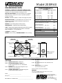
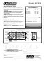
PERFORMANCE
HVI CERTIFIED
Net supply airflow in cfm (L/s) against external static pressure
E.S.P cfm L/s
@ 0.1” (25 Pa) 232 (109)
@ 0.2” (50 Pa) 223 (105)
@ 0.3” (75 Pa) 215 (102)
@ 0.4” (100 Pa) 195 (92)
@ 0.5” (125 Pa) 189 (89)
Maximum Temperature Recovery 81%
Sensible Effectiveness
@ 117 cfm (55 L/s)
(CSA C439M)
74%
Sensible Efficiency
@ 117 cfm (55 L/s) 32˚F (0˚C) 65%
Sensible Efficiency
@ 117 cfm (55 L/s) -13˚F (-25˚C) 66%
VAC @ 60HZ 120
WATTS / Low speed 87
WATTS / High speed 164
Amp rating 1.4
Model 200MAX
ENGINEERING DATA
THERMALLY CONDUCTIVE, PATENTED ALUMINUM CORE
The cross-flow heat recovery core transfers heat between the two
airstreams. It is easily removed for cleaning or service.
MOTORS AND BLOWERS
- Each air stream has one centrifugal
blower driven by a common PSC motor. 5 speed fan operation.
120 VAC, 1.4 Amps.
FILTERS
- Washable air filters in exhaust and supply air streams.
MOUNTING THE HRV
- Four threaded inserts at corners of case
designed to accept four reinforced polyester straps that are
supplied with the unit.
DEFROST
- Recirculating damper defrost system.
DEHUMIDISTAT
- Adjustable Internal Dehumidistat.
CASE
- Twenty gauge prepainted galvanized steel (G60) for superior
corrosion resistance. Insulated to prevent exterior condensation.
Drain connections 2 - 1/2" (12 mm) OD.
CONTROLS
- ControlAir 15
WEIGHT 71 lbs. (32.5 kg SHIPPING WEIGHT 73 lbs. (33.5 kg)
32 5/8"
(828)
STALE AIR
FROM INSIDE
FRESH AIR
FROM OUTSIDE
STALE AIR
TO OUTSIDE
FRESH AIR
TO INSIDE
14 3/4"
(375)
19"
(483)
*All Duct Connections 6" (150mm)
CONDENSATE DRAINS
FILTERS
BLOWERS
*NOTE: Front clearance
of 25 inches (635 mm)
is recommended
for servicing unit.
RECIRCULATING
DEFROST
DAMPER
MOTOR
CORE
DIMENSIONS 200MAX
inches (mm)
OPTIONS
99-104 Digital Electronic Timer - 20/40/60 min.
99-105 Programmable Ventilation Control (PVC)
includes Programmable Time Clock, Dehumidistat
and Air Sentry™
99-109 Air Sentry™ Air Quality Monitor designed to accept
remotely mounted Control Pad
99-250 Ventilation Dehumidistat - Dehumidistat designed to
accept remotely mounted Control Pad.
99-163 Duct Heater w/ Electronic SCR Thermostat, 1 Kw,
6” (150mm)
99-164 Duct Heater w/ Electronic SCR Thermostat, 2 Kw,
6” (150mm)
99-186 Weatherhoods, Two - 6” (150mm)
c/w 1/4” (6mm) mesh screen
All units conform to CSA and UL standards.
WARRANTY
Units carry a LIFETIME warranty on the heat recovery core and
a 5 year replacement parts warranty.
TI-99-NE
0103
DATE: __________________________
PROJECT: __________________________________________
MECHANICAL CONTRACTOR: _____________________________
511 McCormick Blvd.
London, Ontario
N5W 4C8
Ph: (519) 457-1904
Fx: (519) 457-1676
Email: [email protected]
Website: www.lifebreath.com

8
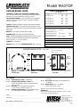
Model MAXTOP
ENGINEERING DATA
THERMALLY CONDUCTIVE, PATENTED ALUMINUM CORE
The cross-flow heat recovery core transfers heat between the two
airstreams. It is easily removed for cleaning or service.
MOTORS AND BLOWERS
- Each air stream has one centrifugal
blower driven by a common PSC motor. 5 speed fan operation.
120 VAC, 1.4 Amps.
FILTERS
- Washable air filters in exhaust and supply air streams.
MOUNTING THE HRV
- Four threaded inserts at corners of case
designed to accept four reinforced polyester straps that are supplied
with the unit.
DEFROST
- Recirculating damper defrost system.
DEHUMIDISTAT
- Adjustable Internal Dehumidistat.
CASE
- Twenty gauge prepainted galvanized steel (G60) for superior
corrosion resistance. Insulated to prevent exterior condensation.
Drain connections 2 - 1/2" (12 mm) OD.
CONTROLS
- ControlAir 15
WEIGHT 87 lbs. (39.5 kg) SHIPPING WEIGHT 89 lbs. (40.5 kg)
PERFORMANCE
HVI CERTIFIED
Net supply airflow in cfm (L/s) against external static pressure
E.S.P cfm L/s
@ 0.1” (25 Pa) 196 (93)
@ 0.2” (50 Pa) 188 (89)
@ 0.3” (75 Pa) 178 (84)
@ 0.4” (100 Pa) 165 (78)
@ 0.5” (125 Pa) 149 (71)
Maximum Temperature Recovery 80%
Sensible Effectiveness
@ 117 cfm (55 L/s )
(CSA C439M)
72%
Sensible Efficiency
@ 117 cfm (55 L/s) 32
O
F (0°C) 64%
Sensible Efficiency
@ 67 cfm (31 L/s) -13
O
F (-25°C)
70%
VAC @ 60HZ 120
WATTS / Low speed 74
WATTS / High speed 164
Amp rating 1.4
TOP VIEW
SIDE VIEW
25 1/2 "
(648 mm)
26 1/2"
(673 mm)
22 1/2"
(572 mm)
FRONT VIEW
ALL DUCT CONNECTIONS
ARE 6" (150 mm)
18"
(457 mm)
7 1/2"
(191 mm)
SUPPLY OF
FRESH AIR
FRESH AIR
SUPPLY
TO BUILDING
STALE AIR
RETURN FROM
BUILDING
STALE AIR
EXHAUST
DRAIN
CONNECTION
CONTROLS
*Service Clearance
25" (635 mm)
¤
DIMENSIONS MAXTOP
inches (mm)
OPTIONS
99-104 Digital Electronic Timer - 20/40/60 min.
99-105 Programmable Ventilation Control
(PVC)
includes Programmable Time Clock, Dehumidistat
and Air Sentry™
99-109 Air Sentry™ Air Quality Monitor designed to
accept remotely mounted Control Pad
99-250 Ventilation Dehumidistat - Dehumidistat designed
to accept remotely mounted Control Pad
99-163 Duct Heater
w/ Electronic SCR Thermostat, 1 Kw,
6” (150mm)
99-164 Duct Heater
w/ Electronic SCR Thermostat, 2 Kw,
6” (150mm)
99-186 Weatherhoods, Two - 6” (150mm)
c/w 1/4” (6mm) mesh screen
All units conform to CSA and UL standards.
WARRANTY
Units carry a LIFETIME warranty on the heat recovery core and
a 5 year replacement parts warranty.
TI-100-NE
0103
DATE: __________________________
PROJECT: __________________________________________
MECHANICAL CONTRACTOR: _____________________________
511 McCormick Blvd.
London, Ontario
N5W 4C8
Ph: (519) 457-1904
Fx: (519) 457-1676
Email: [email protected]
Website: www.lifebreath.com

9
Model 195DCS
49
"
(1245)
STALE AIR
TO OUTSIDE
FRESH AIR
TO INSIDE
14 3/4"
(375)
19"
(483)
Ports
7" (178 mm)
CONDENSATE
DRAINS
BLOWERS
*NOTE:
Front clearance
of 25 inches (635 mm)
is recommended
for servicing unit.
MOTOR
FRESH AIR
FROM OUTSIDE
STALE AIR
FROM INSIDE
FILTER
DEFROST
DAMPER
DEFROST AIR
FROM INSIDE
FILTER
Ports
6" (150 mm)
METAL CLASPS
DIMENSIONS 195DCS
inches (mm)
OPTIONS
99-104 Digital Electronic Timer - 20/40/60 min.
99-105 Programmable Ventilation Control
(PVC)
includes Programmable Time Clock, Dehumidistat
and Air Sentry™
99-109 Air Sentry™ Air Quality Monitor designed to
accept remotely mounted Control Pad
99-250 Ventilation Dehumidistat - Dehumidistat designed
to accept remotely mounted Control Pad.
99-160
Duct Heater w/ Electronic SCR Thermostat,
1 Kw, 7” (178 mm)
99-161
Duct Heater w/ Electronic SCR Thermostat,
2 Kw, 7” (178 mm)
99-186 Weatherhoods, Two - 6” (150 mm)
c/w 1/4” (6mm) mesh screen
All units conform to CSA and UL standards.
WARRANTY
Units carry a LIFETIME warranty on the heat recovery core and
a 5 year replacement parts warranty.
TI-101-NE
0112
ENGINEERING DATA
THERMALLY CONDUCTIVE, PATENTED ALUMINUM CORE
The cross-flow heat recovery core transfers heat between the two
airstreams. The two cores are arranged for highly efficient counter
current airflow.
MOTORS AND BLOWERS - Each air stream has one centrifugal
blower driven by a common PSC motor. 5 speed fan operation.
120 VAC, 1.5 Amps.
FILTERS - Washable air filters in exhaust and supply air streams.
MOUNTING THE HRV - Four threaded inserts at corners of case
designed to accept four reinforced polyester straps that are supplied
with the unit.
DEFROST - Damper defrost system.
DEHUMIDISTAT - Adjustable Internal Dehumidistat.
CASE - Twenty gauge prepainted galvanized steel (G60) for superior
corrosion resistance. Insulated to prevent exterior condensation.
Drain connections 2 - 1/2" (12 mm) OD.
CONTROLS - ControlAir 15
WEIGHT 106 lbs. (48 kg) SHIPPING WEIGHT 108 lbs. (49 kg)
PERFORMANCE
HVI CERTIFIED
Net supply airflow in cfm (L/s) against external static pressure
E.S.P cfm L/s
@ 0.1” (25 Pa) 203 (96)
@ 0.2” (50 Pa) 191 (90)
@ 0.3” (75 Pa) 182 (86)
@ 0.4” (100 Pa) 167 (79)
@ 0.5” (125 Pa) 155 (73)
Maximum Temperature Recovery 88%
Sensible Effectiveness
@ 117 cfm (55 L/s)
(CSA C439M)
88%
Sensible Efficiency
@ 117 cfm (55 L/s) 32
O
F (0°C) 80%
Sensible Efficiency
@ 117 cfm (55 L/s) -13°F (-25
O
C)
77%
VAC @ 60HZ 120
WATTS / Low speed 100
WATTS / High speed 173
Amp rating 1.5
DATE: __________________________
PROJECT: __________________________________________
MECHANICAL CONTRACTOR: _____________________________
511 McCormick Blvd.
London, Ontario
N5W 4C8
Ph: (519) 457-1904
Fx: (519) 457-1676
Email: [email protected]
Website: www.lifebreath.com

10
Model 300DCS
49
"
(1245)
STALE AIR
TO OUTSIDE
FRESH AIR
TO INSIDE
14 3/4"
(375)
19"
(483)
Ports
7" (178 mm)
CONDENSATE
DRAINS
BLOWERS
*NOTE:
Front clearance
of 25 inches (635 mm)
is recommended
for servicing unit.
MOTOR
FRESH AIR
FROM OUTSIDE
STALE AIR
FROM INSIDE
FILTER
DEFROST
DAMPER
DEFROST AIR
FROM INSIDE
FILTER
Ports
6" (150 mm)
METAL CLASPS
DIMENSIONS 300DCS
inches (mm)
OPTIONS
99-104 Digital Electronic Timer - 20/40/60 min.
99-105 Programmable Ventilation Control
(PVC)
includes Programmable Time Clock, Dehumidistat
and Air Sentry™
99-109 Air Sentry™ Air Quality Monitor designed to
accept remotely mounted Control Pad.
99-250 Ventilation Dehumidistat - Dehumidistat designed
to accept remotely mounted Control Pad.
99-160
Duct Heater w/ Electronic SCR Thermostat,
1 Kw, 7” (178 mm)
99-161
Duct Heater w/ Electronic SCR Thermostat,
2 Kw, 7” (178 mm)
99-186 Weatherhoods, Two - 6” (150mm)
c/w 1/4” (6mm) mesh screen
All units conform to CSA and UL standards.
WARRANTY
Units carry a LIFETIME warranty on the heat recovery core and
a 5 year replacement parts warranty.
TI-102-NE
0112
ENGINEERING DATA
THERMALLY CONDUCTIVE, PATENTED ALUMINUM CORE
The cross-flow heat recovery core transfers heat between the two
airstreams The two cores are arranged for highly efficient counter
current airflow.
MOTORS AND BLOWERS - Each air stream has one centrifugal
blower driven by a common PSC motor. 5 speed fan operation.
120 VAC, 2.9 Amps.
FILTERS - Washable air filters in exhaust and supply air streams.
MOUNTING THE HRV - Four threaded inserts at corners of case
designed to accept four reinforced polyester straps that are supplied
with the unit.
DEFROST - Damper defrost system.
DEHUMIDISTAT - Adjustable Internal Dehumidistat.
CASE - Twenty gauge prepainted galvanized steel (G60) for superior
corrosion resistance. Insulated to prevent exterior condensation.
Drain connections 2 - 1/2" (12 mm) OD.
CONTROLS - ControlAir 15
WEIGHT 106 lbs. (48 kg) SHIPPING WEIGHT 108 lbs. (49 kg )
PERFORMANCE
HVI CERTIFIED
Net supply airflow in cfm (L/s) against external static pressure
E.S.P cfm L/s
@ 0.1” (25 Pa) 265 (125)
@ 0.2” (50 Pa) 260 (123)
@ 0.3” (75 Pa) 250 (118)
@ 0.4” (100 Pa) 235 (111)
@ 0.5” (125 Pa) 220 (104)
Maximum Temperature Recovery 90%
Sensible Effectiveness
@ 117 cfm (55 L/s)
(CSA C439M)
90%
Sensible Efficiency
@ 117 cfm (55 L/s) 32°F (0
O
C) 79%
Sensible Efficiency
@ 117 cfm (55 L/s) -13°F (-25
O
C)
75%
VAC @ 60HZ 120
WATTS / Low speed 150
WATTS / High speed 333
Amp rating 2.9
DATE: __________________________
PROJECT: __________________________________________
MECHANICAL CONTRACTOR: _____________________________
511 McCormick Blvd.
London, Ontario
N5W 4C8
Ph: (519) 457-1904
Fx: (519) 457-1676
Email: [email protected]
Website: www.lifebreath.com

11
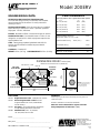
Model 200ERV
®
CLEAN • FRESH • AIR
ENGINEERING DATA
LATENT RECOVERY/MOISTURE TRANSFER CORE
The cross-flow energy recovery core transfers heat and water
vapour between the two airstreams. It is easily removed for
cleaning or service.
MOTORS AND BLOWERS
- Each air stream has one centrifugal
blower driven by a common PSC motor. 5 speed fan operation.
High speed - 120 VAC, 182 Watts.
FILTERS
- Washable air filters in exhaust and supply air streams.
MOUNTING THE ERV
- Four threaded inserts at corners of case
designed to accept four PVC reinforced polyester straps that are
supplied with the unit.
CASE
- Twenty gauge prepainted galvanized steel (G60) for
superior corrosion resistance. Insulated to prevent exterior
condensation.
CONTROLS
- ControlAir 15
WEIGHT 63 lbs. (28.7 kg) SHIPPING WEIGHT 65 lbs. (29.6 kg)
PERFORMANCE
Net supply airflow in cfm (L/s) against external static pressure
E.S.P cfm L/s
@ 0.1” (25 Pa) 214 (101)
@ 0.2” (50 Pa) 206 (97)
@ 0.3” (75 Pa) 193 (91)
@ 0.4” (100 Pa) 184 (87)
@ 0.5” (125 Pa) 170 (80)
Sensible Effectiveness
@127cfm (60 L/s)
(CSA C439M)
67%
Sensible Efficiency 32°F (0°C) 60%
Total Efficiency 55%
VAC @ 60HZ 120
WATTS / Low speed 70
STALE AIR
TO OUTSIDE
FRESH AIR
FROM OUTSIDE
STALE AIR
FROM INSIDE
FRESH AIR
TO INSIDE
14
3
/4"
(375)
19"
(483)
DIMENSIONS 200ERV
inches (mm)
*
All Duct Connections 6"(150mm)
FILTERS
BLOWERS
*NOTE: Front clearance
of 25 inches (635 mm)
is recommended
for servicing unit.
MOTOR
ENTHALPIC CORE
31"
(787)
OPTIONS
99-104 Digital Electronic Timer - 20/40/60 min. (3 wire)
99-105 Deluxe Programmable Control includes
Programmable Time Clock, Dehumidistat
and Air Sentry™
99-109 Air Sentry™ Air Quality Monitor designed to
accept remotely mounted Control Pad
99-186 Weatherhoods, Two - 6” (150mm)
c/w 1/4” (6mm) mesh screen
WARRANTY
Units carry a 5 year warranty on the energy recovery core and
replacement parts.
All units conform to CSA and UL standards.
ERVs are not recommended for regions where the
design temperature is below 25°F (-4°C)
TI-98E
0105
DATE: __________________________
PROJECT: __________________________________________
MECHANICAL CONTRACTOR: _____________________________
511 McCormick Blvd.
London, Ontario
N5W 4C8
Ph: (519) 457-1904
Fx: (519) 457-1676
Email: [email protected]
Website: www.lifebreath.com

12
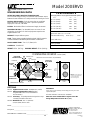
Model 200ERVD
®
CLEAN • FRESH • AIR
ENGINEERING DATA
LATENT RECOVERY/MOISTURE TRANSFER CORE
The cross-flow energy recovery core transfers heat and water vapour
between the two airstreams. It is easily removed for cleaning or service.
MOTORS AND BLOWERS
- Each air stream has one centrifugal
blower driven by a common PSC motor. 5 speed fan operation.
High speed - 120 VAC, 182 Watts.
FILTERS
- Washable air filters in exhaust and supply air streams.
MOUNTING THE ERV
- Four threaded inserts at corners of case
designed to accept four PVC reinforced polyester straps that are
supplied with the unit.
DEFROST
- Damper defrost system.
CASE
- Twenty gauge prepainted galvanized steel (G60) for superior
corrosion resistance. Insulated to prevent exterior condensation.
DRAIN CONNECTIONS
- Two - 1/2” (12mm) O.D.
CONTROLS
- ControlAir 15
WEIGHT 63 lbs. (28.7 kg) SHIPPING WEIGHT 65 lbs. (29.6 kg)
STALE AIR
TO OUTSIDE
STALE AIR
FROM HOUSE
FRESH AIR
TO INSIDE
14
3
/4"
(375)
19"
(483)
DIMENSIONS 200ERVD
inches (mm)
*
All Duct Connections 6"(150mm)
FILTERS
BLOWERS
*NOTE: Front clearance
of 25 inches (635 mm)
is recommended
for servicing unit.
MOTOR
31"
(787)
FRESH AIR
FROM OUTSIDE
DAMPER
DEFROST
PORT
CONDENSATE DRAINS
ENTHALPIC
CORE
OPTIONS
99-104 Digital Electronic Timer - 20/40/60 min. (3 wire)
99-105 Deluxe Programmable Control includes
Programmable Time Clock, Dehumidistat
and Air Sentry™
99-109 Air Sentry™ Air Quality Monitor designed to accept
remotely mounted Control Pad.
99-186 Weatherhoods, Two - 6” (150mm)
c/w 1/4” (6mm) mesh screen
WARRANTY
Units carry a 5 year warranty on the energy recovery core and
replacement parts.
All units conform to CSA and UL standards.
ERVs are not recommended for regions where the
design temperature is below 25°F (-4°C)
TI-200ERVD
0105
DATE: __________________________
PROJECT: __________________________________________
MECHANICAL CONTRACTOR: _____________________________
511 McCormick Blvd.
London, Ontario
N5W 4C8
Ph: (519) 457-1904
Fx: (519) 457-1676
Email: [email protected]
Website: www.lifebreath.com
PERFORMANCE
Net supply airflow in cfm (L/s) against external static pressure
E.S.P cfm L/s
@ 0.1” (25 Pa) 214 (101)
@ 0.2” (50 Pa) 206 (97)
@ 0.3” (75 Pa) 193 (91)
@ 0.4” (100 Pa) 184 (87)
@ 0.5” (125 Pa) 170 (80)
Sensible Effectiveness
@127cfm (60 L/s)
(CSA C439M)
67%
Sensible Efficiency 32°F (0°C) 60%
Total Efficiency 55%
VAC @ 60HZ 120
WATTS / Low speed 70

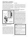
Operating the ControlAir 15
Plugging in the HRV/ERV energizes the unit. A self test
function will be performed every time the HRV/ERV is
energized (refer to “Self Test” for more details). After
the self test has completed successfully the HRV/ERV
will default to Speed 1. This is the factory default
setting. Follow the instructions found on the HRV/ERV
door to select desired mode and speed, or refer to the
instructions found on the following page.
Removing and relocating the
Control Pad
The Control Pad can be removed and installed in a
remote location (100’ wire length max). The Control Pad
can be installed in a 2x4 box with a “Decora” type cover
plate or can be installed in the optional “Ventilation
Dehumidistat” or “Air Sentry”. When the Control Pad is
installed in a remote location, all optional controls will still
be wired to the Control Module on the
HRV/ERV
. When
remotely mounted on its own, the Control Pad is wired to
the Control Module by 3 wire (min. 20 gauge). Connect
the colour coded terminals to the corresponding terminals
on the Control Module. When the Control Pad is remotely
mounted in the Ventilation Dehumidistat or Air Sentry,
refer to optional controls page for wiring requirements.
Self Test
Each time the
HRV/ERV
is powered/energized the self
test function will automatically initiate. During the self
test the
HRV/ERV
will cycle through all the speeds
available (1-5), test the damper motor operation and will
default back to the previous mode/speed selection,
(factory default is Speed 1). Total self test duration is
approximately 1 min. 30 sec.
Automatic Defrost Operation
(Not on all models)
The advanced technology of the digital microprocessor
automatically activates the defrost system only as it is
needed. To be an efficient heat recovery device, the
HRV/ERV must effectively provide for core defrost as well
as providing efficient heat exchange. As outdoor
conditions cool, the temperature sensor (thermistor) tracks
the supply air temperature. The thermistor then sends its
signal to the microprocessor (circuit board) which initiates
only the defrost cycle time required to clear the core. On
recirculating defrost models, the core is defrosted when
the supply air port is automatically blocked off and exhaust
air is redirected back through the HRV/ERV. On damper
defrost models, the core is defrosted when the supply air
port is automatically blocked off and the warm air
surrounding the HRV/ERV is drawn in through the defrost
port. The mode indicator will flash RED during the defrost
cycle. This dramatic advance makes more energy
available for recovery as the unit spends less time in
defrost mode. By optimizing the defrost cycle, the
HRV/ERV combines money saving performance with a
well designed and reliable control system.
FUNCTION & CONTROL
Glossary
DEFROST MODE - to ensure reliable operation during cold
weather, the HRV/ERV will automatically cycle through its
defrost mode as needed. (not on all models)
DEHUMIDISTAT - a control device that senses the amount of
moisture in the air and will activate high speed fan operation
when the air moisture level exceeds the control setting. The
optimum air moisture level (or relative humidity [Rh]) in the
typical home is in the range of 30 to 40% Rh.
RESET - whenever resetting of the HRV/ERV is required,
simply disconnect power for 30 seconds.
STANDBY MODE - the HRV/ERV is energized and waiting for fan
operation to be initiated by a remote device or manual override.
THERMISTOR
- the
HRV/ERV
's temperature sensor which
measures electrical resistance in a known manner, as
outdoor temperatures fluctuate.
ControlAir 15
Exploded view
Control Module
Control Pad
13

14
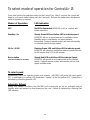
To select mode of operation for ControlAir 15
Press and hold the fan selection button on the Control Pad. After 5 seconds the control will
begin to cycle each mode holding each for 2 seconds. Release the button when the desired
mode of operation is reached.
Modes of Operation LED Indication
OFF No LED’s illuminated HRV/ERV is off, no controls will
initiate operation.
Standby / On Steady Green LED and Yellow LED to indicate speed
HRV/ERV will run at speed selected in ventilation mode.
Standby mode is indicated by no speed indicator
illuminated. Optional remote controls will override standby
or selected speed into high speed.
20 On / 40 Off Flashing Green LED and Yellow LED to indicate speed.
HRV/ERV will operate in ventilation mode at speed selected
for 20 minutes and OFF for 40 minutes.
Recirculation Steady Red LED and Yellow LED to indicate Speed.
*Note: Not available on all models
HRV/ERV
will operate in recirculate mode at the selected
speed. Optional remote controls will override unit into high
speed ventilate mode.
To select speed
Momentarily press fan selection button and release. HRV/ERV will move into next speed.
OFF is indicated by no yellow LED illuminated. Speed 1 is the first yellow LED. Speed five is
indicated by a flashing speed 4 LED.
Automatic Defrost
During cold outdoor conditions the
HRV/ERV
will occasionally go into an automatic defrost
function, which will prevent ice from forming on the core. Defrost is indicated by a flashing Red
LED indicator.

15
ControlAir 15
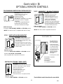
OPTIONAL REMOTE CONTROLS
0011
NEW!
AIR SENTRY™ AIR QUALITY SENSOR
LOCATION: Kitchen, basement,
work place
(connect 1/unit only).
• Digital Air Quality Monitor.
• Status light indicates fan speed.
• Increases ventilation to remove
odours and contaminants.
• Among gases detected are
cigarette smoke and formaldehyde.
• 100' (30 m) maximum wire length.
• Knockout designed to accept Control
Pad when remotely mounted.
PART NO. 99-109
Connects to RED, GREEN and YELLOW terminals.
*NOTE:
This device is NOT compatible with the PVC.
A
IR
S
ENTRY
™
D
IGITAL
A
IR
Q
UALITY
S
ENSOR
FAN SPEED INDICATOR
ControlAir 15
• All controls wire to
matching colour on
the Control Module.
• Control Pad can be
removed and mounted
in a remote location.
•
Control Pad mounts
in a 2”x 4” box or can
be mounted in the
optional Ventilation
Dehumidistat or
Air Sentry.
• Full fan speed control.
DIGITAL ELECTRONIC TIMER (DET)
LOCATION: Bathrooms & kitchen
•
Connect up to 8 on 300
' (91 m) wire max.
•
If a PVC or Air Sentry is used, connect
up to 5 on 300
' wire max.
• Touch pad operation.
• 20/40/60 minute status lights.
• Compact wall mount unit.
• Mounts in 2x4 box.
•
Shown with “decora” cover plate
(99-107W).
PART NO. 99-104
Connects to RED, GREEN and YELLOW terminals.
PROGRAMMABLE VENTILATION CONTROLLER (PVC)
LOCATION: Hallway, kitchen, office
& work place
(connect 1/unit only)
• Advanced digital remote.
• Digital dehumidistat.
• Full fan speed control.
•
AIR SENTRY™
Air Quality Sensor built-in.
•
Recirculation mode (on compatible
HRV/ERVs).
• 7 day, 24 hour programmable timer.
• Digital display and status lights.
• 100' (30 m) maximum wire length.
PART NO. 99-105
Connects to RED, ORANGE, GREEN and YELLOW terminals.
*NOTE:
This device is NOT compatible with the Air Sentry.
NEW! VENTILATION DEHUMIDISTAT
LOCATION: Central location in house.
• Dehumidistat activates high speed
over-ride when humidity level in home
exceeds setting.
• Knockout designed to accept Control
Pad when remotely mounted, giving full
HRV/ERV functionality & control from
remote location.
PART NO. 99-250
Connects to BLACK, RED, GREEN and YELLOW terminals.
*Replaces 99-116 DVC & 99-230 VRD.
*Only compatible with ControlAir 15 electronics.
VENTILATION
DEHUMIDISTAT
•
Three Modes of Operation
- Standby/ON
- 20 ON / 40 OFF
-
Recirculation
(on compatible HRV/ERVs)
Control Module
Control Pad
*See individual control instructions for more details.

16
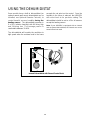
Some models have a built-in dehumidistat (an
optional remote wall mount dehumidistat can be
installed, see Optional Remote Controls), to
control harmful, excess humidity during the
heating season. The dehumidistat operates in
% of RH (relative humidity) with 80 being high
and 20 being low. The average person is
comfortable between 30-45%.
The dehumidistat will overide the ventilator to
high speed when the moisture level in the home
exceeds the set point on the control. Once the
humidity in the house is reduced, the HRV/ERV
will revert back to its previous setting.The
dehumidistat should be set to off for all seasons
except the heating season.
Note: If your HRV/ERV is equipped with an internal
and an external dehumidistat, the internal one can be
turned off and not used.
USING THE DEHUMIDISTAT
Internal Dehumidistat with External Control Knob

17
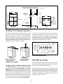
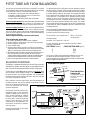
95 MAX Port Specifications
The 95 Max Heat Recovery Ventilator (HRV) has been
designed to allow the installer to choose between two
possible positions on the cabinet for the INDOOR
EXHAUST (return from building) port. Illustrations in this
manual show standard (side mounted) port location . The
same specifications apply to both 95 Max setups,
regardless of which port position is selected.
Variable Port Location / Installation (Model 95 Max only)
The exhaust return port collar is not factory installed.
Installer may choose either side mounted or alternate top
mounted port by simply removing one of the two knock-out
plates and attaching a port collar (supplied). To remove
knock-out plate, insert a utility knife into the knock-out
slits and trace them completely to puncture protective film
underneath. Then, cut the solid tabs between the slits, using
tin snips or side cutters, and remove the knock-out plate. If
any protective film still blocks the opening, remove it now.
In order to make the 95 Max as space efficient as
possible, the INDOOR supply and return ports are
converted from round to oval shape. Overall size of the
port remains the same. Simply bend a standard duct
fitting to the correct shape, and attach to the oval port
using the same method as for a round port.
95 MAX Air Flow
Stale air enters the FRONT RIGHT side port. The air will
pass down the front half of the core, then up the back half
of the core and out the RIGHT REAR port.
Fresh outdoor air will enter the LEFT REAR port and
pass down the back half of the core. It will then pass up
the front half of the core, and out the LEFT FRONT port.
This unique configuration allows the air to actually travel
through the core twice, making the 95 MAX almost as
efficient as a double core unit.
Removably
Heat Recovery
Core
Drain Pan
Drain spout
FRONT TOP
knockout for
side mounting of
EXHAUST return port
6" round collar
converted to oval
minimum
18 inches (459 mm)
required for
service access
Threaded
inserts (4)
at corners
SUPPLY
Fresh air
from outside
5" round collar
SUPPLY
Fresh air
to building
6" round
(conv. to oval)
collar
EXHAUST
Stale Air
to outside
5" round collar
EXHAUST
Return air
from building
Choice of port location
Knockouts on top and
side of unit (use 1 only)
6" round (conv. to oval)
collar supplied
DIMENSIONS 95MAX
inches (mm)
18.5"
(470 mm)
18.5"
(470 mm)
16"
(406 mm)
SIDE
Hanging
straps (4)
24.5"
(622 mm)
HEAT RECOVERY VENTILATORS (HRVs)
¤
HEAT RECOVERY VENTILATORS (HRVs)
¤
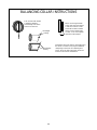
Same Circumference
(6 inch)
diameter
Variable Port Location
SIDE MOUNTED PORT TOP MOUNTED PORT
standard location alternate location
Round port bent to oval

18
INSTALLATION
Location
The HRV/ERV must be located in a heated space where it will
be possible to conveniently service the unit. Typically the
HRV/ERV would be located in the mechanical room or an
area close to the outside wall where the weatherhoods will be
mounted. If a basement area is not convenient or does not
exist, a utility or laundry room may be used
Attic installations are not normally recommended due to:
A) the complexity of work to install
B) freezing conditions in the attic
C) difficulty of access for service and cleaning
Sufficient clearance at the front of the access door is required
for servicing the air filters and core. A minimum of 25" (635
mm) clearance is recommended so the door can be opened.
Four PVC reinforced polyester hanging straps are provided
for hanging the HRV/ERV from the basement floor joists.
Mounting
The hanging straps should be attached to the unit at the top
end corners (mounting screws are already located on the
HRV/ERV case). Securely fasten the other end of the
straps to the floor joists with wide head nails (not
supplied), making sure the unit is level. The straps are
designed to reduce the possibility of noise, resonance or
harmonics; therefore using the full length of the strap between
the HRV/ERV and the floor joists is recommended.
Electrical
The HRV/ERV should be plugged into a standard designated
(120VAC) electrical outlet with ground. It is not recommended
that an extension cord be used for this appliance. If further
wiring is required, then a licensed electrician should make all
electrical connections. It is recommended that a separate 15
amp/120 volt circuit be used.
WARNING:
In order to prevent electric shock when cleaning or servicing
the HRV/ERV, it is extremely important to confirm the
polarity of the power line that is switched by the safety
(disconnect) switch. The hot line (black) is the proper line to
be switched. To confirm the proper polarity, use a voltmeter
or test lamp to ensure there is no power after the switch
when the door is open. Check between that point and ground
(on the cabinet). This must be done as dwellings are
occasionally wired improperly. Always make sure that the
HRV/ERV is properly grounded.
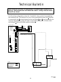
Connecting Appliances to the HRV/ERV
It is not recommended that any of the following appliances be
connected to the HRV/ERV:
• clothes dryer
• range top
• stovetop fan
• central vacuum system
Lint, dust or grease will collect in the HRV/ERV, damaging
the unit.
NOTE:
Connecting any of these to the HRV/ERV will
invalidate your warranty.
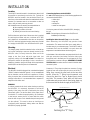
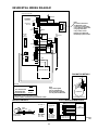
Installing the Drain Line and P-Trap (not on all models)
When defrosting, the HRV/ERV may produce some
condensation. This water should flow into a nearby drain, or
be taken away by a condensate pump. The HRV/ERV and all
condensate lines must be installed in a space where the
temperature is maintained above the freezing point.
At the bottom of the cabinet there are prepunched hole for the
drain pan connectors (see below). Insert the drain spout
through the hole in the drain pan. Do not forget the “O Ring”
which seals the connector to the pan. REMEMBER TO HAND
TIGHTEN ONLY the washer and lock nut which hold the drain
connector in place.
Construct a P-Trap using the plastic tee connector. Cut two
lengths of hose and connect each piece to an end of
the “T”
fitting, then connect the other ends to the two drain
spouts. Allow the "T" fitting to point upwards, and
connect the drain line. Tape or fasten base to avoid
any kinks. This creates a “trap” which will hold some
condensate and prevent odours from being drawn up
the hose and into the fresh air supply of the HRVERV
.
DRAIN
SPOUT
TAPE
TO DRAIN
TEE
CONNECTOR
DRAIN
SPOUT
PRE-PUNCHED HOLES (2)
DRAIN PAN DRAIN PAN
Forming the "P" Trap

INSTALLING AIR DUCTS
A well designed and installed ducting system will allow the
HRV/ERV to operate at its maximum efficiency.
Always try to keep duct runs as short and straight as possible.
See Installation Diagrams for various installation options.
Outside Weatherhoods
The fixed covered hoods have a built-in bird screen with a
1/4" (6 mm) mesh to prevent foreign objects from entering
the ductwork.
Locating the Intake
Weatherhood
• Should be located upstream (if there are prevailing winds)
from the exhaust outlet
• At least 6' (2 m) from the exhaust weatherhood
• At least 6' (2 m) away from dryer vents and furnace
exhaust (medium or high efficiency furnaces)
• A minimum of at least 6' (2 m) from driveways, oil fill
pipes, gas meters, or garbage containers
• At least 18" (457 mm) above the ground,
or above the depth of expected snow accumulation
• At least 3' (1 m) from the corner of the building
• Do not locate in a garage, attic or crawl space
Locating the Exhaust
Weatherhood
• At least 6' (2 m) from the ventilation air intake
• At least 18" (457 mm) above ground or above the depth
of expected snow accumulation
• At least 3' (1m) away from the corner of the building
• Not near a gas meter, electric meter or a walkway
where fog or ice could create a hazard
• Not into a garage, workshop or other unheated space
When installing the weatherhood, its outside perimeter
must be sealed with exterior caulking.
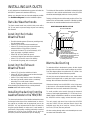
Installing the ducting from the
weatherhoods to the HRV/ERV
The inner and outer liners of the flexible insulated duct must
be clamped to the sleeve of the weatherhoods (as close to
the outside as possible) and the appropriate port on the
HRV/ERV. It is very important that the fresh air intake line
be given special attention to make sure it is well sealed. A
good bead of high quality caulking (preferably acoustical
sealant) will seal the inner flexible duct to both the
HRV/ERV port and the weatherhood prior to clamping.
To minimize air flow restriction, the flexible insulated duct that
connects the two outside weatherhoods to the HRV/ERV
should be stretched tightly and be as short as possible.
Twisting or folding the duct will severely restrict air flow. See
below for the recommended connection of flexible insulated
ducts to the the outside weatherhoods and the HRV/ERV.
Warmside Ducting
To maximize airflow in the ductwork system, all ducts should
be kept short and have as few bends or elbows as possible.
Forty-five degree elbows are preferred to 90° elbows. Use
“Y” tees instead of 90° elbows whenever possible.
All duct joints must be fastened with screws, rivets or duct
sealant and wrapped with a quality duct tape to prevent
leakage. We recommend aluminum foil duct tape.
Galvanized ducting from the HRV/ERV to the living areas
in the house is recommended whenever possible, although
flexible duct can be used in moderation if necessary.
To avoid possible noise transfer through the ductwork
system, a short length (approximately 12 " or 300 mm) of non-
metallic flexible insulated duct should be connected between
the HRV/ERV and the supply/ exhaust ductwork system.
The main supply and return lines to/from the HRV/ERV
must be 6 inches (150 mm) minimum. Branch lines to the
individual rooms may be as small as 4 inches (100 mm),
but 5 inch (125 mm) lines are preferred .
All ducts running through attics and unheated spaces must
be sealed and insulated to code.
HOOD
BIRD
SCREEN
BELT OF OUTSIDE WALL
THERMAL COLLAR
INSULATED FLEXIBLE
DUCTING
1/ Thermal Collar slides over galvanized
sleeve of Weatherhood.
2/ Fasten Thermal Collar to Belt.
3/ Slide the Insulated Flexible Ducting over
the Weatherhood’s galvanized sleeve and
fasten it to the Thermal Collar.
4/ Hood is hinged to allow for easy access
for cleaning of bird screen.
WEATHERHOOD INSTALLATION
19

20
SUPPLY AIR DUCTING
In homes without a forced air furnace, fresh air should be
supplied to all bedrooms and living areas, excluding
bathrooms, kitchen and utility areas. It should be supplied
from high wall or ceiling locations. Grilles that diffuse the air
comfortably such as the Techgrille™ are recommended.
If the floor is the only option available, then special care
should be taken in locating grilles. Areas such as under
baseboard heaters will help to temper the air. Also optional
inline duct heaters are available for mounting in the supply
duct work to add heat if required.
In homes with a forced air furnace, you may want to connect
the HRV/ERV to the furnace ductwork (see information below).
Direct Connection to Furnace Ductwork
Should you wish to hard duct the supply air directly into the
cold air return of the furnace, remember to check the air
flow balance of the HRV/ERV with the furnace fan both
"ON" and "OFF" to determine that it does not imbalance the
unit more than 10%. Also, it is advisable to include a short
length of fabric flex duct or other non-metallic connector in
this hard ducted line in order to keep the HRV/ERV
separately grounded (electrically) from the furnace. This will
avoid a possible shock hazard to service people if a short to
ground develops in one of the devices.
Indirect Connection to Ductwork
If permitted by local codes, an indirect connection may be
made between the HRV/ERV supply duct and the furnace
return plenum. The fresh air from the unit may be directed
at a grille installed in the cold air return duct of the furnace.
The fresh air supply outlet from the unit should be no closer
than 4 inches (100 mm) and no more than 12 inches (300
mm) from the grille.
Stale Air Exhaust System
The stale air exhaust system is used to draw air from the
points in the house where the worst air quality problems
occur. It is recommended that return air ducts are installed
in the bathroom, kitchen, and laundry room. Additional
return air ducts from strategic locations (i.e. greenhouse,
atrium, swimming pool, sauna, etc.) may be installed. Also,
the furnace return duct may be used to exhaust from. In this
method, the exhaust air is not ducted back to the HRV/ERV
with "dedicated lines" from bathrooms, kitchens, etc.
Instead, the exhaust air is drawn out of the cold air return of
the forced air furnace. This method has become popular
and provides good ventilation when installed in accordance
with the instructions. The furnace blower must be running
when the unit is operating for this system to
be effective.
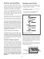
Dampers and Grilles
The use of balancing dampers and/or adjustable grilles to
balance the flow rates into various rooms is recommended.
We suggest TECHGRILLE™ air diffusers.
• The TECHGRILLE™ is available in 4", 5", 6" and 8" (100,
125, 150 and 200 mm) sizes.
• The TECHGRILLE™ is a round, fully adjustable grille,
which provides superior, quiet air distribution.
We recommend the use of high mounted wall returns with
grilles. The exhaust air duct from the kitchen should never be
connected to a range hood. Instead, the exhaust grille
should be mounted high on the wall at least 4 feet (1.2 m)
horizontally away from the stove. A "flip-up", 6" X 10" (150 X
250 mm) rectangular kitchen grille with removable grease
filter is available (Part No. 10-002).
Dampers should be located just prior to the HRV/ERV to
balance the stale air exhausted out of the house with a fresh
air supply entering the house.
AIR FLOW
SUPPLY
AIR FLOW
EXHAUST
Techgrille Air Diffusers
Kitchen Grille
Removable
filter
Page is loading ...
Page is loading ...
Page is loading ...
Page is loading ...
Page is loading ...
Page is loading ...
Page is loading ...
Page is loading ...
Page is loading ...
Page is loading ...
Page is loading ...
Page is loading ...
-
 1
1
-
 2
2
-
 3
3
-
 4
4
-
 5
5
-
 6
6
-
 7
7
-
 8
8
-
 9
9
-
 10
10
-
 11
11
-
 12
12
-
 13
13
-
 14
14
-
 15
15
-
 16
16
-
 17
17
-
 18
18
-
 19
19
-
 20
20
-
 21
21
-
 22
22
-
 23
23
-
 24
24
-
 25
25
-
 26
26
-
 27
27
-
 28
28
-
 29
29
-
 30
30
-
 31
31
-
 32
32


Lifebreath Stereo Amplifier 155MAX User manual
- Category
- Air filters
- Type
- User manual
Ask a question and I''ll find the answer in the document
Finding information in a document is now easier with AI
Related papers
-
Lifebreath CONTROLAIR 15 95MAX Installation guide
-
-
Lifebreath 200MAX RX User manual
-
-
-
-
-
Lifebreath 170 ERVD Owner's manual
-
Lifebreath METRO 120ERVD-ECM Owner's manual
-
Lifebreath RNC4-TPD Owner's manual
Other documents
-
Barco OverView cDR80-DL Owner's manual
-
Graintex RS1597 Operating instructions
-
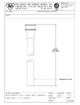 T & S Brass & Bronze Works B-0618-01 Datasheet
-
Carrier HRVCCSHB1100 User manual
-
Bryant ERVBBSVA1100 User manual
-
 Web WPAD Operating instructions
-
La Crosse 104-108 Installation guide
-
 American Aldes HRV 120SRD User manual
-
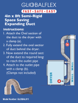 GLOBALFLEX Global011 Installation guide
-


