Page is loading ...

•
m
•
n
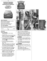
ENGLISH
TOOLS REQUIRED:
Drill (3/32” Drill Bit), Philips Head Screwdriver,
10mm Socket & Ratchet or 10mm Wrench, Wire Crimpers,
Wire Cutters, Trim Panel Remover
1. Mazda 6 Sedan and Coupe
A. Locate the vehicle wiring inside the vehicle's rear cargo
area by partially removing the plastic threshold cover
and felt trunk liner
d
.
B. On the driver’s side only, using a 10mm socket, remove
two nuts on the back of the vehicle taillight housing.
Then pull the taillight housing directly rearward to
remove
e
. Separate the vehicle's wiring connectors,
being careful not to break the locking tabs. Remove the
taillight housing and set aside.
C. At the driver’s side taillight socket, clean an area using
a mixture of rubbing alcohol and water and apply the
foam-padded tape. Make sure to cover any sharp edges
on the sheet metal, as shown
f
. Route approximately
2 ft (.60 meters) of the black 12 ga. wire into the trunk
area. Route the remaining wire through the opening in
the taillight socket, behind the bumper. Carefully replace
the vehicle taillight housing; making sure the black wire
is in between the taillight housing’s gasket and the
foam-padded tape. Make sure taillight is properly seated
on alignment tap. Replace with the two 10 mm nuts
removed in step B.
Toyota Camry
A. Locate the vehicle wiring inside the vehicle's rear cargo
area by partially removing the plastic threshold cover
and felt trunk liner
g
. On the Driver’s side remove the
small plastic cargo tray, by removing the plastic nuts
that hold it in place
h
.
B. In the area underneath from where the plastic cargo
tray was removed, locate a small rubber grommet
i
.
Carefully slit the grommet and route the black 12 ga.
wire out underneath the vehicle.
Mazda CX-7
A. Locate the vehicle wiring inside the vehicle's rear cargo
area by partially removing all floor coverings, cargo
trays, plastic threshold cover, access panels and trim
panels, being careful not to damage and clips or
screws. Set aside all items removed being careful
not to damage parts.
B. On the Passenger’s side, near the threshold area, locate
rubber grommet. Carefully slit the grommet and route
the black 12 ga. wire out underneath the vehicle.
NOTE
Toyota FJ Cruiser Instructions begin after step 9.
2. Behind the taillights, there will be connection points match-
ing the ends of the T-Connector adapter on the back of each
of the vehicle taillight housings
jkl
. On the driver’s
side, attach each end of the T-Connectors containing the
yellow and the red wires. Ensure that the connectors are
fully inserted with locking tabs in place.
3. Route the T-Connector containing the green wire below the
threshold cover to the passenger’s side taillight housing.
Repeat step 4 using the T-Connector ends containing the
green wire.
4. From inside the trunk, connect the black 12 ga. wire and the
red wire from the T-Connector black box with the supplied
yellow butt connector.
5. Locate a suitable grounding point near the connector.
Option 1:
Clean dirt and rustproofing from the area. Drill a 3/32"
hole and secure the white wire using the eyelet and
screw provided.
Option 2:
Locate existing ground stud. Loosen bolt, place screw
eyelet on stud and re-tighten bolt
m
.
CAUTION
Verify what is behind any surface prior to drilling to avoid
damage to the vehicle and/or personal injury. Do not drill
into any exposed surfaces.
6. On the driver’s side underneath the bumper, locate the
black 12 ga. wire from Mazda 6 Sedan and Coupe step C,
Toyota Camry step B and Mazda CX-7 step B. Following
existing wiring, route the black wire into the engine
compartment up to the battery
n
.
WARNING
Route the wire being careful to avoid any hot pipes, heat
shields, the fuel tank or any other points that may pinch
or break the wire.
7. Disconnect the vehicle's Negative (-) battery cable.
If not removed, remove the fuse from the yellow fuse
holder (provided). After cutting the fuse holder wire,
attach the ring terminal and secure to the vehicle's
Positive (+) battery cable. Connect the other end of the
fuse holder to the black 12 ga. wire, using the Yellow
butt connector (provided)
n
.
8. Reconnect the vehicle's Negative (-) battery cable
and install the 10 amp fuse into the fuse holder from
step 7
n
.
WARNING
All connections must be complete for the T-Connector to
function properly. Test and verify installation with a test
light or trailer once installed.
9. Secure the remainder of the T-Connector harness with the
cable ties provided, to prevent damage or rattling and
being careful to avoid any areas that would cut or pinch
the wire. On the driver’s side on the floor of the rear cargo
area, clean a flat area using a mixture of rubbing alcohol
and water. Mount the T-Connector black box using
double-sided tape provided. Replace the trunk threshold
and felt trunk liner.
NOTE
Store 4-Flat in rear cargo area when not in use.
WARNING
Overloading circuit can cause fires. DO NOT exceed lower
of towing manufacturer rating or:
• Max. stop/turn light: 1 per side (2.1 amps)
• Max. tail lights: (4.2 amps)
Read vehicle's owners manual & instruction sheet for
additional information.
PAGE 2 OF 6
•
j
•
k
•
l
NOTE: Toyota FJ Cruiser Instructions begin on Page 4.
REMARQUE: Les instructions pour la Toyota FJ Cruiser commencent à la Page 4.
NOTA: Las instruciones del Toyota FJ empiezan en la Página 4.

PAGE 5 OF 6
ENGLISH
Toyota FJ Cruiser ONLY
1. Open the rear door. Remove the jack storage compartment
door on the Driver’s side. Remove the five screws holding
the threshold in place
o
. Using a trim panel tool, carefully
pry the threshold plate away from the vehicle, being careful
not to damage any clips.
2. Remove the two Phillip head screws on the Driver’s side
& Passenger’s side connecting the trim panel to the vehicle
floor
p
. Using a Phillips head screwdriver, remove the
cargo clips on both sides of the vehicle. Remove the
access panels on each side to gain access to the
connection points
q
.
NOTE
If the vehicle is equipped with an optional subwoofer unit
on the Passenger side, there will be no cargo clip and the
access panel will not be accessible unless the Subwoofer
unit is removed.
3. If the vehicle is equipped with an optional subwoofer
unit, see Subwoofer Removal steps below. Otherwise,
skip to Step 5.
Subwoofer Removal
A. Using a trim panel remover tool, remove access
panel just below the Subwoofer unit
r
.
B. Using a trim panel remover tool, carefully remove
the front trim/grill assembly from the subwoofer unit.
There will be eight (8) clips holding it in place
s
.
C. Using a 10mm socket remove the four (4) 10mm bolts
holding the subwoofer unit in place
t
.
NOTE
An extension will be needed to remove the two
upper bolts holding the subwoofer unit in place.
D. Locate the wiring harness just below the unit, pull the
retaining clip from the bracket and carefully disconnect
the harness
u
. Carefully pull out the subwoofer unit a
set aside in an area where it will not be damaged.
E. Remove the access panel behind the Passenger side
taillight to gain access to the connection points.
4. Using a trim panel remove tool carefully pull back the
interior trim panels on both Driver’s side and Passenger’s
side
v
.
5. On the Driver’s side, locate the trailer wiring harness
w
.
Route the harness containing the Red wire and the harness
containing the Yellow wire behind the trim panel up to the
access panel location
x
.
6. Locate the vehicle’s three (3) pin rear tail lamp connector
and separate from the tail lamp assembly
w
. Plug the
harness containing the Red wire in between these separated
halves. Be sure that the connectors are fully inserted.
NOTE
The tail lamp plug area is very small and may be difficult for
hands to reach inside. Long nose pliers may be used to
assist in the removal and connection of the plugs.
7. Locate the vehicle’s two (2) pin rear tail lamp connector
and separate from the tail lamp assembly. Plug the harness
containing the Yellow wire in between these separated
halves. Be sure that the connectors are fully inserted.
8. Route the harness containing the Green wire to the
Passenger’s side. Start by routing the harness out of the
Driver’s side trim panel, route along the rear threshold area,
behind the Passenger’s side trim panel up to the access
panel location.
9. Repeat step 7 using the harness containing the Green wire.
10. Inside of the Jack Storage compartment, locate the bracket
holding the jack in place. Using a 10mm socket remove the
bolt to the left of the jack
y
.
11. Locate the White wire with the ring terminal. Attach the
White wire with the ring terminal and re-tighten.
12. Disconnect the vehicle's Negative (-) battery cable. If not
removed, remove the fuse from the Yellow fuse holder (pro-
vided). After cutting the fuse holder wire, attach the ring ter-
minal and secure to the vehicle's Positive (+) battery cable.
Connect the other end of the fuse holder to the Black 12 ga.
wire, using the Yellow butt connector (provided).
13. Beginning from the front of the vehicle, route the black 12
ga. wire rearward along the frame rail avoiding any hot
pipes, heat shields, the fuel tank or any other points that
may pinch or break the wire.
14. Continuing on as illustrated, route the black 12 ga. wire to
the rear driver's side. Locate the rubber grommet located
near the wheel well and cut a hole in the grommet and route
the wire up through this hole and attach the black 12 ga.
wire to the red wire from the T-Connector Black Box with
the supplied yellow butt connector.
15. Reconnect the vehicle's Negative (-) battery cable and
install the 10 amp fuse into the fuse holder from step 12.
WARNING
All connections must be complete for the T-Connector to
function properly. Test and verify installation with a test
light or trailer once installed.
16. Replace the interior trim panels, access panels, rear
threshold plate, cargo clips, jack storage compartment
cover and subwoofer unit removed during installation.
NOTE
Make sure subwoofer connection plug is fully inserted.
WARNING
Overloading circuit can cause fires. DO NOT exceed lower
of towing manufacturer rating or:
• Max. stop/turn light: 1 per side (2.1 amps)
• Max. tail lights: (4.2 amps)
Read vehicle's owners manual & instruction sheet for
additional information.
•
w
•
u
•
x
•
v
•
y
Toyota FJ Cruiser
/