• Be aware that you cannot measure the temperature of air
between the Infrared thermometer and an object. Air vents
(registers) are quick to take on the temperature of outlet air.
However, you must aim directly at the vent if you are measuring
outlet air temperature.
• Keep your infrared thermometer away from strong electrical
fields. When working near a strong electrical field, like that under
the hood of your car, watch for unusual readings or an "over
load" indication. Often, you can move the thermometer just a few
inches to escape the influence of the interference.
• Keep your INF185/215 within its use and storage temperature
range. Excessive heat or cold will adversely affect the accuracy of
your readings. When the trigger is pulled the target’s temperature
will be displayed in a near real-time mode (less than 1/2 second
between measurements). The temperature will remain on the dis
play for seven seconds after the trigger is released.
Mode and Functions
Press the “MODE” push-button will scroll through the following options:
: E m i s s i v i ty data. (The default emissivity is 0.95)
: Press the “MODE” push-button, then press “ “ or “ “
push-buttons to set the emissivity, then press the “MODE”
push-button again to confirm it. The emissivity can be
changed from 0.10 to 1.
: Press the “MODE” push-button for the maximum (MAX),
minimum (MIN), different between MAX and MIN (DIF)
and average (AVG) modes. During the measurement, the
special modes reading will be displayed at the bottom of
the display near the mode icon.
: Press the “ “ or “ “ push-buttons to change the
“High Alarm” (HAL) or “Lo Alarm” (LAL), then press the
trigger to confirm it. For example: when the reading 27˚C <
LAL 27.1˚C, the low “Lo Alarm” icon will flash and you will
hear a beep sound.
: Connect the thermocouple to the thermocouple socket
and apply the probes to the target being measured. The
thermometer will display the temperature automatically
without pressing any buttons. To see the minimum or
m aximum data during the probe measurement, please
hold down the “ “ or “ “ push-buttons.
WARNING!
After measurement of high temperature, the probe may be hot for
a while.
Operating Instructions
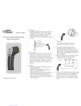
Taking Measurements
To take a temperature measurement using your INF185/215, you simply
point the aperture at an object (with or without using the laser sighting)
and pull the trigger. The object’s temperature will show up on the
display and update at a rate of approximately 2 times per second.
There will be a delay of approximately one-second between the time
you initially pull the trigger and the time the display comes on. The 60-
second auto-hold initiates at the moment you release the trigger. The
m a ximum temperature is viewed beside the “ “ icon.
NOTE: This thermometer will automatically shut off if left idle for more
than 60 seconds, unless in PRB mode. When in PRB mode, instrument
will shut off if left idle for more than 12 minutes.
Follow these general guidelines to ensure you get the most accurate
readings possible:
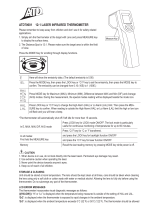
• Be sure the measured object fills the "spot" seen by the
aperture. The distance to spot ratio for the INF185 is
12:1. The distance to spot ratio for the INF215 is 30:1.
This shows the one-foot spot fitting within the one-foot target area. At
this distance, and anything closer, the target’s temperature will be
accurately measured (Fig 1).
NOTE: If the two-foot diameter spot includes unwanted objects in
the background that are not part of the one-foot square target. The
temperature of the background objects will be figured in with the
target’s temperature and throw off your measurement.
• When comparing temperatures of similar objects that are far away,
take your measurements at the same distance and angle to the
target each time.
• When looking for abnormally hot or cold targets it may be
acceptable to include background objects so long as the
temperatures in the background and your methods are consistent.
• Consider the emissivity of the objects you are measuring.
• Prepare a surface for measurement. Infrared thermometers
measure only the outer surface of an object. If emissivity is affecting
the measurement, or you have difficulty putting the object in the
sensors line-of-site, you may need to prepare a surface that’s easy
for the infrared thermometer to read. A piece of masking tape is a
good target and it will rapidly take on the temperature of the object
it is attached to.
INF185/215-MAN P. 2
(Fig 1)