Page is loading ...

2
TABLE OF CONTENTS
General Power Tool Safety Warnings .............................3-4
Safety Warnings for Router .....................................5-6
Symbols .....................................................7-9
Get to Know Your Router ........................................10
Specications .................................................11
Operating Instructions .......................................12-25
Maintenance ................................................ 26-27
Extension Cords ...............................................27
Troubleshooting ...............................................27
Limited Warranty of SKIL Consumer Tools ..........................28
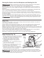
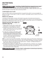
WARNING
•
Some dust created by power sanding, sawing, grinding, drilling and other construction
activities contains chemicals known to the State of California to cause cancer, birth defects
or other reproductive harm. Some examples of these chemicals are:
–
Lead from lead-based paints.
–
Crystalline silica from bricks, cement, and other masonry products.
–
Arsenic and chromium from chemically-treated lumber.
•
Your risk from these exposures varies, depending upon how often you do this type of work.
To reduce your exposure to these chemicals:
–
Work in a well-ventilated area.
–
Work with approved safety equipment, such as dust masks that are specially designed to
lter out microscopic particles.
–
Avoid prolonged contact with dust from power sanding, sawing, grinding, drilling, and
other construction activities. Wear protective clothing and wash exposed areas with soap
and water. Allowing dust to get into your mouth or eyes or to lie on the skin may promote
absorption of harmful chemicals.

3
GENERAL POWER TOOL SAFETY WARNINGS
WARNING
Read all safety warnings, instructions, illustrations and specications
provided with this power tool.
Failure to follow all instructions listed
below may result in electric shock, re and/or serious injury.
SAVE ALL WARNINGS AND INSTRUCTIONS FOR FUTURE
REFERENCE.
The term “power tool” in the warnings refers to your mains-operated (corded) power tool or
battery-operated (cordless) power tool.
Work area safety
Keep work area clean and well lit
. Cluttered or dark areas invite accidents.
Do not operate power tools in explosive atmospheres, such as in the presence of
ammable liquids, gases or dust.
Power tools create sparks which may ignite the dust or
fumes.
Keep children and bystanders away while operating a power tool.
Distractions can cause
you to lose control.
Electrical safety
Power tool plugs must match the outlet. Never modify the plug in any way. Do not use
any adapter plugs with earthed (grounded) power tools.
Unmodied plugs and matching
outlets will reduce risk of electric shock.
Avoid body contact with earthed or grounded surfaces, such as pipes, radiators,
ranges and refrigerators.
There is an increased risk of electric shock if your body is earthed
or grounded.
Do not expose power tools to rain or wet conditions.
Water entering a power tool will
increase the risk of electric shock.
Do not abuse the cord. Never use the cord for carrying, pulling or unplugging the power
tool. Keep cord away from heat, oil, sharp edges or moving parts.
Damaged or entangled
cords increase the risk of electric shock.
When operating a power tool outdoors, use an extension cord suitable for outdoor use.
Use of a cord suitable for outdoor use reduces the risk of electric shock.
If operating a power tool in a damp location is unavoidable, use a ground fault circuit
interrupter (GFCI) protected supply.
Use of a GFCI reduces the risk of electric shock.
Personal safety
Stay alert, watch what you are doing and use common sense when operating a power
tool. Do not use a power tool while you are tired or under the inuence of drugs,
alcohol or medication.
A moment of inattention while operating power tools may result in
serious personal injury.
Use personal protective equipment. Always wear eye protection.
Protective equipment
such as a dust mask, non-skid safety shoes, hard hat or hearing protection used for
appropriate conditions will reduce personal injuries.
Prevent unintentional starting. Ensure the switch is in the off-position before
connecting to power source and/or battery pack, picking up or carrying the tool.
Carrying power tools with your nger on the switch or energising power tools that have the
switch on invites accidents.
Remove any adjusting key or wrench before turning the power tool on.
A wrench or a
key left attached to a rotating part of the power tool may result in personal injury.
Do not overreach. Keep proper footing and balance at all times.
This enables better
control of the power tool in unexpected situations.

4
Dress properly. Do not wear loose clothing or jewellery. Keep your hair and clothing
away from moving parts.
Loose clothes, jewellery or long hair can be caught in moving
parts.
If devices are provided for the connection of dust extraction and collection facilities,
ensure these are connected and properly used.
Use of dust collection can reduce dust-
related hazards.
Do not let familiarity gained from frequent use of tools allow you to become complacent
and ignore tool safety principles
. A careless action can cause severe injury within a fraction
of a second.
Power tool use and care
Do not force the power tool. Use the correct power tool for your application.
The correct
power tool will do the job better and safer at the rate for which it was designed.
Do not use the power tool if the switch does not turn it on and off.
Any power tool that
cannot be controlled with the switch is dangerous and must be repaired.
Disconnect the plug from the power source and/or remove the battery pack, if
detachable, from the power tool before making any adjustments, changing accessories,
or storing power tools.
Such preventive safety measures reduce the risk of starting the
power tool accidentally.
Store idle power tools out of the reach of children and do not allow persons unfamiliar
with the power tool or these instructions to operate the power tool.
Power tools are
dangerous in the hands of untrained users.
Maintain power tools and accessories. Check for misalignment or binding of moving
parts, breakage of parts and any other condition that may affect the power tool’s
operation. If damaged, have the power tool repaired before use.
Many accidents are
caused by poorly maintained power tools.
Keep cutting tools sharp and clean.
Properly maintained cutting tools with sharp cutting
edges are less likely to bind and are easier to control.
Use the power tool, accessories and tool bits etc. in accordance with these instructions,
taking into account the working conditions and the work to be performed.
Use of the
power tool for operations different from those intended could result in a hazardous situation.
Keep handles and grasping surfaces dry, clean and free from oil and grease.
Slippery
handles and grasping surfaces do not allow for safe handling and control of the tool in
unexpected situations.
WARNING
When using power tools, basic safety precautions should always be
followed to reduce the risk of re, electric shock, and personal injury.
WARNING
The operation of any tool can result in foreign objects being propelled into
your eyes, resulting in severe eye damage. When operating power tool,
always wear safety goggles or safety glasses with side shields and a full face shield when
needed.
WARNING
If any parts are missing, do not operate the tool until the missing parts
have been replaced. Doing so could result in serious personal injury.
Service
Have your power tool serviced by a qualied repair person using only identical
replacement parts.
This will ensure that the safety of the power tool is maintained.
If any part of this router is missing or should break, bend,
or fail in any way; or should
any electrical component fail to perform properly: shut off the power switch and remove the
plug from the power source and have the missing, damaged, or failed parts replaced before
resuming operation.

5
SAFETY WARNINGS FOR ROUTER
Hold the power tool by insulated gripping surfaces only, because the cutter may
contact its own cord.
Cutting a “live” wire may make exposed metal parts of the power tool
“live” and could give the operator an electric shock.
Use clamps or another practical way to secure and support the workpiece to a stable
platform.
Holding the work by your hand or against the body leaves it unstable and
may lead
to loss of control.
Maintain a rm grip
on the router with both hands to resist starting torque.
Never attempt to use the router motor without rst installing it in an approved xed
base.
Failure to heed this warning could result in personal injury and damage to the motor.
Make sure that the motor housing does not move up or down when clamped in the
xed base. If the motor is not securely clamped into the base, injury could result and
adjustments will not be accurate.
Do not hand-hold the router in an upside down or horizontal position.
The motor can
separate from the base if not properly attached according to the instructions.
Tighten the collet/nut securely to prevent the cutter bit from slipping.
If the collet/nut is
not securely tightened, the cutter bit may detach during use, causing serious personal injury.
Never tighten the collet/nut without a cutter bit installed in the collet/nut.
Never hold the piece being cut in your hands or across your legs.
It is important to
support and clamp the workpiece properly in order to minimize body exposure, bit binding, or
loss of control.
Always keep the chip shield clean and in place.
Stay alert and clear the router cutter bit path of any obstructions before starting the
motor.
Keep cutting area clear of all foreign objects while the motor is running.
Inspect and remove all nails from lumber before routing.
Check to see that the cord will not “hang up” during routing operation.
Make sure that the cutter bit is not in contact with the workpiece before the switch
is turned on. The bit must always be running at full speed before contacting the
workpiece.
Keep hands clear
of the cutter bit when the motor is running to prevent personal injury.
Provide clearance under the workpiece
for the router cutter bit when through-cutting.
Keep cutting pressure constant.
Do not overload the motor.
Use only sharp cutter bits
that are not chipped or cracked. Blunt cutter bits will cause stalling
and burn the workpiece.
Never use this router motor with a cutter bit larger than 3-1/2 inches in diameter.
Always use cutter bits that are designed for this router. Never use cutter bits which
are larger in diameter than the opening in the router sub-base.
Cutter bits that have
cutter diameters larger than the opening could cause possible loss of control or create other
hazardous condition that could cause serious personal injury.
The sub-base on this router has an opening of 1-1/4 inches.
To use cutter bits with a
larger diameter, install and use a sub-base with a larger
diameter opening.
Do not use large router cutter bits for freehand routing.
Use of large cutter bits when
freehand routing could cause loss of control or create hazardous conditions that could result in
serious personal injury. If using a router table, large bits should be used for edging only.
Be sure that the cutter bit is centered in a template guide
(sold separately) prior to
template guide applications to avoid personal injury or damage to nished work.
Do not remove more than 1/8 inch in a single pass.
Excessive depth of cut can result in
loss of control that could result in personal injury.

6
After completing a cut, turn the motor OFF and let it come to complete stop before
removing router from workpiece. Let the motor come to a complete stop before putting
the router down.
Cutter bits coast after the power is turned off.
Only use router tables with on-board switch-controlled receptacles.
Failure to use router
tables with all the appropriate safety features could result in serious personal injury.
Disconnect the tool from the power source
before making any adjustments or changing
cutter bits.
If you are changing a bit immediately after use, be careful not to touch the collet/nut
or cutter bit with your hands or ngers.
The heat buildup from cutting could cause severe
burns. Always use the wrench provided.
Avoid “climb cutting;” see “Feeding the Router” section in this manual.
“Climb cutting”
increases the chance for loss of control resulting in possible serious injury.
Only use router bits suitable for the no-load speed of the tool.
Never use router bits with a diameter exceeding the maximum diameter specied in the
technical data section.
WARNING
Bits, sockets, and tools get hot during operation. Wear gloves when
touching them.
WARNING
Wear ear protection. Exposure to noise can cause hearing loss.
WARNING
To avoid injury, hold the tool by the insulated gripping surfaces only. If the
tool contacts hidden wiring or its own cord, exposed metal parts of the tool
could shock the operator and cause serious injury. Make sure that hidden electrical wiring,
water pipes, or other hazards are not in the cutting path.

7
SYMBOLS
Safety Symbols
The purpose of safety symbols is to attract your attention to possible dangers. The safety
symbols and the explanations with them deserve your careful attention and understanding.
The symbol warnings do not, by themselves, eliminate any danger. The instructions and
warnings they give are no substitutes for proper accident prevention measures.
WARNING
Be sure to read and understand all safety instructions in this
Operator’s
Manual, including all safety alert symbols such as “
DANGER
,”
“
WARNING
,” and “
CAUTION
” before using this tool. Failure to following all instructions listed
below may result in electric shock, re, and/or serious personal injury.
The denitions below describe the level of severity for each signal word. Please read the manual
and pay attention to these symbols.
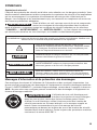
This is the safety alert symbol. It is used to alert you to potential
personal injury hazards. Obey all safety messages that follow this
symbol to avoid possible injury or death.
DANGER
DANGER indicates a hazardous situation which, if not avoided, will
result in death or serious injury.
WARNING
WARNING indicates a hazardous situation which, if not avoided, could
result in death or serious injury.
CAUTION
CAUTION, used with the safety alert symbol, indicates a hazardous
situation which, if not avoided, will result in minor or moderate injury.
Damage Prevention and Information Messages
These inform the user of important information and/or instructions that could lead to equipment
or other property damage if they are not followed. Each message is preceded by the word
“NOTICE”, as in the example below:
NOTICE:
Equipment and/or property damage may result if these instructions are not followed.
WARNING
The operation of any power tools can result in
foreign
objects being thrown into your eyes, which can result
in severe eye damage. Before beginning power tool operation, always
wear safety goggles or safety glasses with side shields and a full face
shield when needed. We recommend a Wide Vision Safety Mask for use
over eyeglasses or standard safety glasses with side shields. Always use
eye protection which is marked to comply with ANSI Z87.1.

8
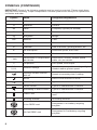
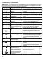
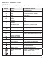
SYMBOLS (CONTINUED)
IMPORTANT:
Some of the following symbols may be used on your tool. Please study them
and learn their meaning. Proper interpretation of these symbols will allow you to operate the
tool better and safer.
Symbol Name Designation/Explanation
V Volts Voltage (potential)
A Amperes Current
Hz Hertz Frequency (cycles per second)
W Watt Power
kg Kilograms Weight
min Minutes Time
s Seconds Time
Ø Diameter Size of drill bits, grinding wheels, etc.
n
0
No load speed Rotational speed, at no load
n Rated speed Maximum attainable speed
…/min
Revolutions or reciprocation
per minute
Revolutions, strokes, surface speed,
orbits, etc. per minute
0 Off position Zero speed, zero torque...
1,2,3,…
I,II,III,
Selector settings
Speed, torque or position settings. Higher
number means greater speed
Innitely variable selector
with off
Speed is increasing from 0 setting
Arrow Action in the direction of arrow
Alternating current Type or a characteristic of current
Direct current Type or a characteristic of current
Alternating or direct current Type or a characteristic of current
Class II tool
Designates Double Insulated Construction
tools.
Earthing terminal Grounding terminal
Li-ion RBRC seal
Designates Li-ion battery recycling
program
Ni-Cad RBRC seal
Designates Ni-Cad battery recycling
program

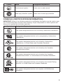
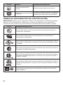
9
Symbol Name Designation/Explanation
Read manual symbol Alerts user to read manual
Wear eye protection symbol Alerts user to wear eye protection
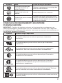
SYMBOLS (CERTIFICATION INFORMATION)
IMPORTANT:
Some of the following symbols for certication information may be used on your
tool. Please study them and learn their meaning. Proper interpretation of these symbols will
allow you to operate the tool better and safer.
Symbol Designation/Explanation
This symbol designates that this tool is listed by Underwriters Laboratories.
This symbol designates that this tool is recognized by Underwriters
Laboratories.
This symbol designates that this tool is listed by Underwriters
Laboratories, to United States and Canadian Standards.
This symbol designates that this tool is listed by the Canadian
Standards Association.
This symbol designates that this tool is listed by the Canadian
Standards Association, to United States and Canadian Standards.
This symbol designates that this tool is listed by the Intertek Testing
Services, to United States and Canadian Standards.
This symbol designates that this tool complies to NOM Mexican
Standards.

10
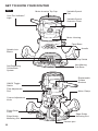
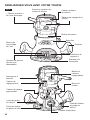
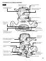
GET TO KNOW YOUR ROUTER
Fig. 1
“Live Tool Indicator”
Light
Motor-housing Top Cap
Variable-Speed
Selection Chart
Variable-Speed
Dial
Motor Housing
Chip Shield
Handle
Fixed Base
Non-Marring
Sub-Base
Self-Releasing
Collets/Nuts
System
Spindle-lock
Button
Motor Clamp
Edge-Guide
Mounting Slot
Vacuum port
Replaceable
Carbon
Brushes
Fine-Adjustment
Dial
Coarse-Adjustment
Knob
Edge-Guide
Lever
Edge Guide
Mounting Slot
ON/Off Toggle
Switch

11
SPECIFICATIONS
Power Input 120V~,60Hz,10A
No-Load Speed 10,000-25,000 RPM
Collet Capacities 1/4 in. and 1/2 in.
Sub-Base Opening (Diameter for
cutter bit use)
1-1/4 inches

12
OPERATING INSTRUCTIONS
Selecting the Cutter Bit
This router comes with a 1/2” collet and 1/4” collet sleeve that accept cutter bits with 1/2” and
1/4” shanks, respectively. The 1/2” collet is installed on the tool, and the 1/4” collet sleeve can
be installed inside the 1/2” collet.
WARNING
Do not use a router cutter bit that has a cutter bit diameter larger than 1-1/4
inches with the sub-base that is installed on this router, as it will not t
through the sub-base opening, will cause damage to the sub-base and the motor, and could
cause serious personal injury to the operator.
WARNING
Always turn the motor off and unplug the router before making any
adjustments or installing accessories. Failure to unplug the router could
result in accidental starting, which can cause serious personal injury.
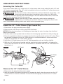
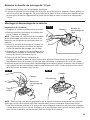
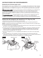
Install the 1/4” Collet Sleeve (Figs 2a and 2b)
1. Disconnect the plug from the power supply.
2. Remove the router motor housing from the xed base.
NOTICE:
See the instructions for installing and removing the motor housing from the xed
base in this manual.
3. Set the router motor upside down on the motor-housing top cap with the collet pointing up.
4. Press the spindle-lock button to engage and lock the spindle shaft and the 1/2” collet. Place
the wrench (included) on the 1/2” collet and turn it counterclockwise to loosen the collet
slightly to accept the 1/4” collet sleeve (g 2a).
5. Insert the 1/4” collet sleeve into the 1/2” collet assembly as far as it will go (g 2b).
6. With the 1/4” collet sleeve inserted and the spindle-lock button pressed in to engage the
shaft, place the wrench on the 1/2” collet and turn it clockwise until the 1/4” collet sleeve is
tightened in it.
Fig. 2a
1/2” Collet
Spindle-lock
Button
Fig. 2b
1/4” Collet
Sleeve
Remove the 1/4” Collet Sleeve
1. Disconnect the plug from the power supply.
2. With the spindle-lock button pressed in to engage the shaft, place the wrench on the 1/2”
collet and turn it counter-clockwise to loosen the collet slightly to remove the 1/4” collet
sleeve.

13
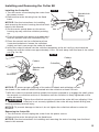
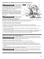
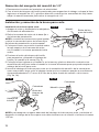
Installing and Removing the Cutter Bit
Installing the Cutter Bit
1. Turn the motor off and unplug the router from
the power source.
2. Remove the motor housing from the xed
base.
NOTICE:
See the instructions for installing
and removing the motor housing from the xed
base in this manual.
3. Set the motor upside down on the motor-
housing top cap, with the collet/nut pointing
up.
4. Press the spindle-lock button to engage and
lock the spindle shaft and collet/nut (Fig. 3).
5. Place the wrench on the collet/nut and turn
it counterclockwise to loosen the collet/nut
slightly so that it can accept the cutter bit shank.
6. Insert the cutter bit shank into the collet/nut assembly as far as it will go, then back the
shank out until the cutters are approximately 1/8 to 1/4 inch away from the face of the collet/
nut (Fig. 3a, 3b).
Fig. 3a
Bit Shank
Cutters
Spindle-lock
Button
Fig. 3b
Collet/Nut
Cutters
NOTICE:
To ensure proper gripping of the cutter bit shank and minimize run-out,
the shank of the cutter bit must be inserted into the collet/nut at least 5/8 inch.
7. With the cutter bit inserted and the spindle-lock button pressed in to engage the shaft, place
the wrench on collet/nut and turn it clockwise until the collet/nut is rmly tightened on the
cutter bit shank.
WARNING
Tighten the collet/nut securely to prevent the cutter bit from slipping. If the
collet/nut is not securely tightened, the cutter bit may detach during use,
causing serious personal injury.
NOTICE:
To prevent damage to the tool, do not tighten the collet/nut without a cutter bit
installed.
Removing the Cutter Bit
1. Turn the motor off and unplug the router from the power source.
2. Remove the motor housing from the xed base.
NOTICE:
See the instructions for installing and removing the motor housing from the xed
base in this manual.
Fig. 3
Nut
Collet
Spindle-lock
Button

14
3. Set the motor housing upside down on the motor-housing top cap, with the collet/nut
pointing up.
4. Press the spindle-lock button to engage and lock the spindle shaft and the collet/nut (Fig. 3).
5. Place the wrench on the collet/nut and turn it counterclockwise to loosen the collet/nut
slightly; remove the cutter bit shank.
Collet/Nut Care
Before each use, inspect the collet/nut to make sure that it is clean and that it is gripping the
cutter bit properly.
With the router cutter bit removed, press the spindle-lock button and turn the collet/nut
counterclockwise until it is free from the motor spindle shaft. Blow the collet with compressed
air, and clean the tapered inside of the collet/nut with a tissue or a ne brush.
Always make sure that the cutter bit shank, collet/nut and motor spindle are clean and free of
woodchips, dust, residue, grease and rust before installing a cutter bit or collet/nut.
Apply a slight amount of machine oil to the spindle shaft if it looks dry.
Replace a worn or damaged collet/nut immediately.
NOTICE:
The collet/nut is self-releasing; it is not necessary to strike the collet/nut to free the
router cutter bit. If the cutter bit seems to be stuck after use, loosen collet/nut a little more until
it releases.
Cutter Bits
For faster, more accurate cutting results, keep cutter bits clean and sharpen. Remove all
accumulated pitch and gum from cutter bits after each use.
When sharpening cutter bits, sharpen only the inside of the cutting edge. Never
grind the outside diameter. Be sure, when sharpening the end of a cutter bit, to
grind so that the clearance angle is the same as was originally ground.
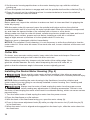
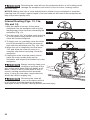
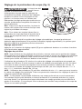
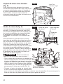
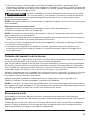
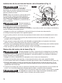
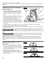
Installing the Router Motor Housing (Fig. 4)
WARNING
Never use the router motor without installing it into either an approved
xed or plunge base. Failure to do so could result in serious personal injury
and damage to the motor.
NOTICE:
Before installing the motor housing in the xed base, have the collet/nut and
router cutter bit you are going to use already installed in motor housing. See “Installing and
Removing the Cutter Bit”.
WARNING
Always turn the motor off and unplug the router from the power source
before making any adjustments or installing accessories. Failure to turn
the motor off and unplug the router could result in accidental starting, which can cause serious
personal injury.
1. Turn the router motor off and unplug the router from the power source.
2. Place the xed base on a at surface.
3. With the back of the xed base facing you, open the motor clamp (A).
4. Press in the coarse-adjustment knob (B) while you align the motor slot (C) with the pin (D)
in the xed base.
5. When the motor’s slot is aligned and engaged into the base’s pin, slide the motor down into
the xed base.

15
6. The router motor will now slide up or down to set coarse adjustments when the coarse-
adjustment knob is pressed in.
7. After all adjustments are made, close the motor clamp securely.
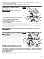
Removing the Motor from the
Base (Fig. 4)
WARNING
Always turn the motor off
and unplug the router from
the power source before making any
adjustments or installing accessories. Failure
to turn the motor off and unplug the router
could result in accidental starting, which can
cause serious personal injury.
1. Turn the motor off and unplug the router from
the power source.
2. Place the router (xed base and motor
housing) on a at surface.
3. With the back of the router facing you, open
the motor clamp (A).
4. Push in the coarse adjustment knob (B) to release the motor slot (C) from the pin (D) in the
xed base, while you lift the router motor free of the xed base.
5. Set the motor housing upside down on the motor-housing top cap with the collet pointing up
and remove the cutter bit.
WARNING
Always remove the cutter bit from collet/nut when the router is not being
used. Leaving bits installed could result in accidents causing serious
personal injury.
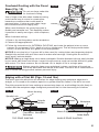
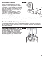
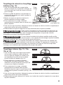
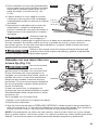
Adjusting the Depth of Cut (Fig. 5)
WARNING
Your router should never be
turned on or be connected
to the power source when you are assembling
parts, making adjustments, installing or
removing collets/nuts, cutter bits, cleaning the
product or when it is not in use. Disconnecting
the router will prevent accidental starting,
which could cause serious personal injury.
NOTICE:
All depth adjustments on the xed
base must be made with the motor clamp
open.
NOTICE:
For all xed base routers, the cutter
bit depth equals the amount of the cutter that is
exposed below the surface of the sub-base.
The xed base is designed with a micrometer-ne adjustment system. When the bit is lowered
to the approximate position desired (coarse setting), the system then can be micro-adjusted to
the precise depth required.
Coarse Adjustment
Depressing the coarse adjustment knob (B) allows you to quickly lower or raise the cutter bit
to an approximate depth setting.
Fig. 4
D
B
C
A
Fig. 5
B
A
D
C

16
Fine Adjustments
NOTICE:
Be sure that the micrometer-ne adjustment system is engaged before making ne
adjustments. Test it by turning the ne adjustment dial (C) clockwise and counter-clockwise to
see if the bit lowers and raises.
The depth indicator ring (D) located on the ne adjustment dial is marked in 1/256- inch
increments. Turning the ne adjustment dial counterclockwise 180° (1/2 turn), lowers the
cutter bit 1/32 inch. One full turn counterclockwise 360° (zero “0” to zero “0”) lowers the bit
1/16 inch.
NOTICE:
The depth-indictor ring (D) may be reset to zero “0” without moving the ne
adjustment dial. This allows the user to begin adjustments from any reference point desired.
NOTICE:
Making a single deep cut is never advisable. Smaller diameter cutter bits are easily
broken by too much side thrust and torque. Larger cutter bits will cause a rough cut and be difcult
to guide and control. For these reasons, do not exceed 1/8 in. depth of cut in a single pass.
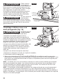
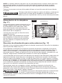
Toggle “On/Off” Switch
Use the toggle switch located on the top cap of
the motor housing to turn the router “ON” and
“OFF”.
The left side of the toggle switch hood (as you
face it) is marked “I” for “On” and the right side
(as you face it) is marked “O” for “Off”.
To turn the motor “ON”, push the toggle switch
to the left side marked “I”, or “On”. To turn the
motor “OFF” push the toggle switch to the right
side marked “O”, or “Off”.
Contact the workpiece with the router and
cutter bit only after the router has reached full
speed. Turn the router motor “OFF” and allow
the cutter bit to come to a complete stop before
removing the router and cutter bit from the workpiece.
Soft-Start Feature
The soft-start feature minimizes torque twist, customary in larger router motors, by limiting the
speed at which the motor starts. This increases the motor’s life.
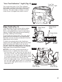
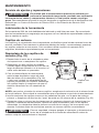
LED Worklights (Fig. 7)
Your router motor has 3 built-in worklights
located around the collet/nut to provide high
visibility of workpiece when cutting. These
lights are always “On” when the toggle switch
is in the “On” position.
Fig. 6
Fig. 7

17
“Live Tool Indicator” Light (Fig. 8)
Your router also has a “Live Tool Indicator”
green light, located on the motor housing top
cap where the power cord enters the motor
housing. This green light is always on when
router motor is plugged into power source.
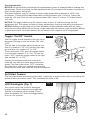
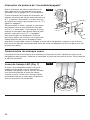
Edge Guide (Fig. 9)
The Fixed-Base Router comes with an edge
guide. This edge guide can be used as an
aid in routing applications such as decorative
edging, straight edge planning and trimming,
grooving, dadoing, and slotting.
To assemble the edge guide, insert two edge-
guide rods into the holes on the edge guide,
and then use two screws (included) to lock the
edge-guide rods in place.
To attach the edge guide to the xed base,
simply insert the edge guide rods into the edge
guide mounting slots either from the left or
the right. Adjust the edge guide to the desired
position. Secure the edge guide by turning the
edge guide levers toward two handles.
NOTICE:
If the inner screws wear down or
become loose, to tighten the inner screws:
•
Pull the lever up to strip from the hex nut of
the inner screw, turn the edge-guide lever
clockwise (for the right edge guide lever)
or counterclockwise (for the left edge guide
lever) then push the lever down (Fig. 10).
•
Turn the edge-guide lever counterclockwise
(for the right edge guide lever) or clockwise
(for the left edge guide lever) to secure the
edge guide rod.
Fig. 8
"Live Tool
Indicator" Light
Fig. 9
Edge Guide
Lever
Edge Guide
Rods
Edge Guide
Screws
Fig. 10
Hex Nut of
Inner Screw
Hex Nut of
Inner Screw

18
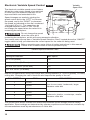
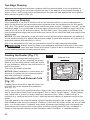
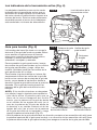
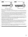
Electronic Variable Speed Control
The electronic variable-speed control feature
allows the router motor speed to be matched
to cutter size and material hardness for an
improved nish and extended bit life.
Speed changes are made by rotating the
speed control dial to the “LEFT” to increase
the speed, and to the “RIGHT” to decrease
the speed as indicated on the dial, numbered
1 through 6 (Fig. 11) .The speed may be
changed while the router is “ON”, but do
not change the speed when the cutter bit is
contacting the workpiece.
WARNING
Do not change the speed
when the cutter bit is
contacting the workpiece, as this will cause excessive vibration.
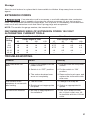
Your router motor top cap has a “Variable Speed Selection Chart” located above the “ON/OFF”
toggle switch to help you determine the correct speed for the cutter bit being used.
WARNING
Before operating your router follow all safety instructions in this manual.
Failure to do so could result in serious personal injury.
Variable Speed Selection Chart
Never exceed these bit speeds
Cutting-Bit Diameter Max.Speed
UP to 1in.(25mm) 5-6
1 1/4-in. to 2-in. (30-50mm) 3-4
2 1/4-in. to 2 1/2-in. (55-65 mm) 2-3
3-in. to 3 1/2-in. (75-90mm) 1-2
Reduce the speed when using extra-large bits (cutting diameter of 1 inch or greater), or heavy
cutting bits. Changing the rate of feed can also improve the quality of the cut.
DIAL SETTING RPM APPLICATION
1 10,000
Non-ferrous metal, hardwoods, larger
diameter cutter bits
2 13,000
3 16,000
4 19,000
Softwoods, plastics, countertops, smaller
diameter cutter bits
5 22,000
6 25,000
The speed charts above indicate the relationship between speed settings and the cutting
application. Exact settings are determined by operator experience and reference, and also by
recommendations made by manufacturers of cutter bits.
Fig. 11
Variable
Speed Dial

19
Placing the Router onto the Workpiece and Starting the Cut
WARNING
Before operating the router follow all safety instructions in this manual.
Failure to do so could result in serious personal injury.
NOTICE:
Making test cuts is essential with most routing applications. A test cut will give a
feel for the set-up, the router’s speed, the depth of cut, and how the cutter bit reacts to the
workpiece.
Much of routing is a trial-and-error process of making various adjustments, followed by test
cuts. To avoid ruining good material, make your test cuts on scrap materials.
How you place your router onto a workpiece (starting the cut) with a xed base depends on
the type of routing you are going to produce: edge routing or internal routing, as discussed on
the following pages.
For ease of operation and to maintain proper control, your router has two handles: one on
each side of the router base. When operating the router, always hold it rmly with both hands.
WARNING
Always be alert and watch what you are doing. Never operate the router
when you are fatigued.
Deep Cuts
The proper cutting depth for each pass is always determined by the material, the cutter bit
size and type, and power of the motor.
Always make several progressively deeper cuts: start at one depth and then make several
passes, each time increasing the cutting depth, until your desired depth is reached.
Making a cut that is too deep will stress the router motor and the cutter bit, and it may burn the
workpiece and dull the cutter bit. It could also “grab” too much of the workpiece and cause you
to lose of control of the router, causing a serious accident.
To be certain that your depth settings are correct, always make test cuts in scrap material
similar to your workpiece before beginning the nal cutting operation.
Remember, knowing the right depth for each cut comes with routing experience.
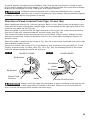
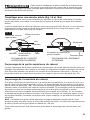
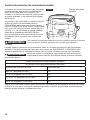
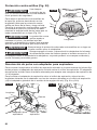
Edge Routing (Fig. 12)
1. With the depth-of-cut set, place the router on
the edge of workpiece, making sure that the
cutter does not contact the workpiece.
2. Clamp an edge guide (board or metal
straightedge) in place to help guide the
router base.
3. Turn the router “On”, and allow the motor to
reach the selected speed.
4. To begin your cut, gradually feed the cutter
bit into the edge of the workpiece.
5. When the cut is complete, turn motor “Off”
and allow cutter bit come to a complete stop
before removing it from the workpiece.
6. Unplug the router from the power source, and inspect the nished cut in the workpiece.
WARNING
Always securely clamp your workpiece and keep a rm grip on the router
base with both hands at all times. Failure to do so could result in loss of
control, causing possibly serious personal injury.
Fig. 12
Edge
Guide
Remove Arrow
Edging with
Fixed Base

20
WARNING
Removing the cutter bit from the workpiece while it is still rotating could
damage the workpiece and result in loss of control, causing serious
personal injury.
NOTICE:
Making test cuts in scrap material that is similar to your workpiece is essential.
Learning how the router’s speed, depth-of-cut and cutter bit will react in the workpiece will
help you produce quality cuts.
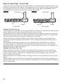
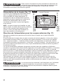
Internal Routing (Figs. 13, 13a,
13b and 14)
1. With the depth-of-cut set, tilt the router
and place it on the workpiece with only the
leading edge of the sub-base contacting the
workpiece (Fig. 13).
2. Turn the motor “On” and allow motor build up
to its full speed, being careful not to let the
cutter bit contact workpiece.
3. To begin your cut, gradually lower the cutter
bit into the workpiece until the sub-base is
ush with the workpiece (see Fig. 13a, 13b).
4. When the cut is completed, turn the motor
“Off” and allow the cutter bit come to a
complete stop before removing it from the
workpiece.
5. Unplug the router from the power source,
place the router upside down on the
worktable, and inspect the nished cut in the
workpiece.
WARNING
Always securely clamp your
workpiece and keep a rm
grip on the router base with both hands at all
times. Failure to do so could result in loss of
control, causing possible serious personal
injury. If using a router table, large cutter bits
should be used for edging only.
WARNING
Removing the cutter bit
from the workpiece while it
is still rotating could damage the workpiece
and result in loss of control, causing serious personal injury.
Fig. 13
Fig. 13a
Fig. 13b
Fig. 14
Routing

21
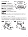
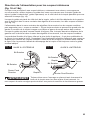
Freehand Routing with the Fixed
Base (Fig. 15)
WARNING
Do not use large cutter bits
for freehand routing.
Use of large cutter bits when freehand routing
could cause loss of control or create other
hazardous conditions that could result in
personal injury. If using a router table, large
bits should be used for edging only.
When used freehand, the router becomes a
exible and versatile tool. This exibility makes
it possible to easily rout signs, relief sculptures,
etc.
When freehand routing:
1. Draw or lay out the pattern on the workpiece.
2. Choose the appropriate bit.
3. Follow the instructions for INTERNAL ROUTING, and route the pattern in two or more
passes. Do not exceed 1/8-in. depth of cut in a single pass. This will help provide better
control, as well as serve as a guide on the next passes.
NOTICE:
A core-box bit or V-groove bit is often used for routing letters and engraving objects.
Straight bits and ball mills are often used to make relief carvings. Veining bits are used to
carve small, intricate details.
NOTICE:
Making a single deep cut is never advisable. Smaller-diameter bits are easily broken
by too much side thrust and torque. Larger bits will cause a rough cut and be difcult to guide
and control. For these reasons, do not exceed 1/8- in. depth of cut in a single pass.
WARNING
Always securely clamp your workpiece in place, and keep a rm grip on
the router base with both hands at all times. Failure to do so could result in
loss of control causing possible serious personal injury.
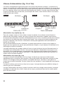
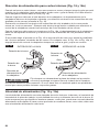
Edging with a Pilot Bit (Figs. 16 and 16a)
The arbor-type bits with pilots are excellent for edge shaping any workpiece edge that is
straight, or is curved at a curvature equal to or greater than the radius of the bit to be used.
The pilot prevents the bit from making an excessively deep cut, and holding the pilot rmly in
contact with the workpiece edge throughout prevents the cut from becoming too shallow.
Fig. 16
Spindle Lock
Cutter-bit
Pilot
Fixed Base
Sub-base
Work-piece
TOP EDGE SHAPING
Motor Housing
Spindle
Collet/Nut
Fig. 16a
Workpiece
Guide Board
Whole Edge of Workpiece
WHOLE EDGE SHAPING
Fig. 15
Page is loading ...
Page is loading ...
Page is loading ...
Page is loading ...
Page is loading ...
Page is loading ...
Page is loading ...
Page is loading ...
Page is loading ...
Page is loading ...
Page is loading ...
Page is loading ...
Page is loading ...
Page is loading ...
Page is loading ...
Page is loading ...
Page is loading ...
Page is loading ...
Page is loading ...
Page is loading ...
Page is loading ...
Page is loading ...
Page is loading ...
Page is loading ...
Page is loading ...
Page is loading ...
Page is loading ...
Page is loading ...
Page is loading ...
Page is loading ...
Page is loading ...
Page is loading ...
Page is loading ...
Page is loading ...
Page is loading ...
Page is loading ...
Page is loading ...
Page is loading ...
Page is loading ...
Page is loading ...
Page is loading ...
Page is loading ...
Page is loading ...
Page is loading ...
Page is loading ...
Page is loading ...
Page is loading ...
Page is loading ...
Page is loading ...
Page is loading ...
Page is loading ...
Page is loading ...
Page is loading ...
Page is loading ...
Page is loading ...
Page is loading ...
Page is loading ...
Page is loading ...
Page is loading ...
Page is loading ...
Page is loading ...
Page is loading ...
Page is loading ...
Page is loading ...
Page is loading ...
Page is loading ...
Page is loading ...
Page is loading ...
Page is loading ...
Page is loading ...
Page is loading ...
-
 1
1
-
 2
2
-
 3
3
-
 4
4
-
 5
5
-
 6
6
-
 7
7
-
 8
8
-
 9
9
-
 10
10
-
 11
11
-
 12
12
-
 13
13
-
 14
14
-
 15
15
-
 16
16
-
 17
17
-
 18
18
-
 19
19
-
 20
20
-
 21
21
-
 22
22
-
 23
23
-
 24
24
-
 25
25
-
 26
26
-
 27
27
-
 28
28
-
 29
29
-
 30
30
-
 31
31
-
 32
32
-
 33
33
-
 34
34
-
 35
35
-
 36
36
-
 37
37
-
 38
38
-
 39
39
-
 40
40
-
 41
41
-
 42
42
-
 43
43
-
 44
44
-
 45
45
-
 46
46
-
 47
47
-
 48
48
-
 49
49
-
 50
50
-
 51
51
-
 52
52
-
 53
53
-
 54
54
-
 55
55
-
 56
56
-
 57
57
-
 58
58
-
 59
59
-
 60
60
-
 61
61
-
 62
62
-
 63
63
-
 64
64
-
 65
65
-
 66
66
-
 67
67
-
 68
68
-
 69
69
-
 70
70
-
 71
71
-
 72
72
-
 73
73
-
 74
74
-
 75
75
-
 76
76
-
 77
77
-
 78
78
-
 79
79
-
 80
80
-
 81
81
-
 82
82
-
 83
83
-
 84
84
-
 85
85
-
 86
86
-
 87
87
-
 88
88
-
 89
89
-
 90
90
-
 91
91
-
 92
92


Ask a question and I''ll find the answer in the document
Finding information in a document is now easier with AI
in other languages
- français: Skil RT1323-00 Le manuel du propriétaire
- español: Skil RT1323-00 El manual del propietario