Bosch NGP736UC/01 Installation guide
- Category
- Cookers
- Type
- Installation guide
This manual is also suitable for

Gas Requirements
Supply Pressure
Natural Gas - 6 inches water column
(14.9 Millibars) minimum.
Propane Gas - 11 inches water column
(27.4 Millibars) minimum.
The maximum gas pressure to this appliance is
not to exceed 14.0 inches water column (34.9 Mil-
libars).
PROPANE GAS INSTALLATION (NGT models only)
Note: NGP models cannot be converted for propane
use.
The propane gas tank must be equipped with its
own high pressure regulator in addition to the pres-
sure regulator supplied with this unit.
The cooktop is shipped from the factory for use
with natural gas. For use with LP, a conversion kit
is required and must be purchased separately.
Contact BSH or your retailer to obtain kit #
NEZ1065. A qualified technician or installer must
do the conversion.
Leak testing of the appliance shall be conducted
according to manufacturer’s instructions.
Do Not Discard This Sheet
Important Safety Instructions
• Installation must conform with local codes or,
in the absence of local codes, with the Na-
tional Fuel Gas Code, ANSI Z223.1.
• The appliance must be electrically grounded in
accordance with local codes or, in the absence
of local codes, with the National Electrical Code
ANSI/NFPA 70, latest edition. (In Canada, in-
stallation must be in accordance with the CAN
1-B149.1 and .2 Installation Codes for Gas Burn-
ing Appliances and/or local codes)
• This appliance has been tested in accordance
with ANS Z21.1,
Standard for Household
Cooking Appliances (USA) and in accordance
with CANl.l-M81 Interim Reqt #58 Domestic
Gas Cooktops (CANADA).
WARNING: Improper installation, ad-
justment, alteration, service or main-
tenance can cause injury or property damage.
Refer to this manual. For assistance or addi-
tional information consult a qualified installer,
service agency, manufacturer or the gas sup-
plier.
INSTALLATION INSTRUCTIONS MANUAL
STEEL GAS COOKTOPS with FULL-SURFACE GRATES
30" MODELS: NGT73, NGP73
36" MODELS: NGT93, NGP93
Power Requirements and Grounding
Power Supply: 120 Volts, 15 Ampere, 60 Hz. This
appliance is factory equipped with a 5-foot power
supply cord with a 3-prong grounding plug (with
polarized parallel blades).
TO PREVENT ELECTRICAL SHOCK, THE
THIRD GROUND PRONG SHOULD NOT UN-
DER ANY CIRCUMSTANCES, BE CUT OR
REMOVED. IT MUST BE PLUGGED INTO A
MATCHING GROUNDING TYPE RECEPTACLE
AND CONNECTED TO A CORRECTLY POLAR-
IZED 120-VOLT CIRCUIT. A separate circuit is
recommended which is in compliance with the
NEC.
If there is any doubt as to whether the wall recep-
tacle is property grounded, the customer should
have it checked by a qualified electrician.
CAUTION: Before you plug in an electrical
cord, be sure all controls are in the OFF posi-
tion.
!
IMPORTANT: Save these instructions for the local electrical inspector’s use.
INSTALLER: Please leave these Installation Instructions with this unit for the owner.
OWNER: Please retain these instructions for future reference.
PLEASE READ INSTRUCTION BEFORE PROCEEDING
• The cooktop must be used in conjunction with
a suitable ventilation system.

PAGE 2
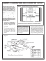
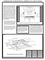
CABINET CONSIDERATIONS AND COUNTERTOP CUTOUT
Figure 2
Cutout Dimensions are Underlined
Figure 1 – Installed Dimensions (from cooktop edges)
Cooktop to front of countertop – 1-1/4" minimum
Dimensions are minimum clearances to combustible materials
Plan the installation of the unit so
that the power cord, gas shut-off
valve and gas pressure regulator are
accessible from the front of cabinet.
If a drawer is installed directly under
the cooktop, its depth (front to
back) should be no greater than 15".
Dimension requirements in Figs. 1
& 2 are for combustible surfaces.
When the surface is protected by a
material listed by UL as a Floor
Protector and Wall Shield and is
covered with not less than No. 28
MSG sheet metal, 0.015-inch
stainless steel, or 0.024-inch
aluminum or copper, it is considered
noncombustible and some
dimensions may be reduced. For a
noncombustible surface over the
cooktop, the minimum clearance is
24" rather than 30".
• Instructions are based on
standard American cabinets 36"
high x 24" deep with a 25"
countertop.
• Provide approximately a 10-
square-inch opening in the toe
kick area or other cabinet area
for adequate air inlet to the
cabinet.
NOTICE: All measurements
given in Figures 1 and 2 have to
be precisely followed. If non-
standard cabinets are used,
make sure they are installed with
minimum dimensions shown in
Fig. 1 and Fig. 2.
Cooktop Depth

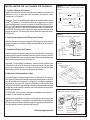
PAGE 3
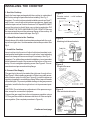
Heat Reflective Tape
Cutout shows location
of Aluminum Reflective Tape
Section "A - A"
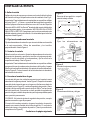
1. Seal the Cooktop
Apply the foam tape packaged with the cooktop to underside of
the cooktop along the perimeter before installing. See Fig. 3.
Important: For solid surface material installations such as Surel™
and Corian
®
, consult with solid surface manufacturer. Apply heat
reflective tape such as Scotch
®
Aluminum Foil Tape #425 or #427
around the cutout so that it folds over on the top and sides. DO
NOT WRAP THE TAPE UNDERNEATH THE COOKTOP. Be sure
the tape extends beyond the outermost flange of the cooktop. All
corners should be covered with tape. See Fig 3.
2. Attach Brackets to the Cooktop
Attach clamps of the hold-down brackets packaged with the cook-
top to the rough-in box. Use the washers and screws provided. See
Fig. 4.
3. Install the Cooktop
Insert cooktop into the cutout. Adjust hold-down brackets to de-
sired position and tighten screws to rough-in box. Insert adjusting
screw into clamp and secure cooktop to countertop. See Fig. 4.
Important: For solid surface material installations, insert a wooden
block between the end of the screw and the bottom of the coun-
tertop. Do not overtighten adjusting screw. See Figure 4. Trim ex-
cess aluminum tape around cooktop flange.
4. Connect Gas Supply
The gas inlet to the unit is located at the right rear of rough-in box.
See Figure 5. After installing a gas shut-off valve in an easily acces-
sible location under the unit (see Figure 6), install the pressure
regulator (supplied) to manifold pipe using Teflon
®
tape on threads
of manifold pipe. To prevent possible damage to the gas pressure
regulator, install it after the rough-in box is in its permanent posi-
tion.
CAUTION: Do not attempt any adjustment of the pressure regu-
lator, except for conversion to propane.
Connect the gas supply line to the unit pressure regulator using a
1/2" flex gas line connector between wall shut-off valve and pres-
sure regulator. (See complete procedure in Figure 6.)
INSTALLING THE COOKTOP
Figure 3
Counter cutout – solid surface
countertops
Figure 4
Attaching hold-down brackets
Figure 5
Rough-in Box area.
Figure 6
Gas and electrical location.
Continued next page
Opening for Gas
Connection &
Electrical Cord
for 30" models - 12-5/8"
for 36" models - 12-1/2"

PAGE 4
We reserve the right to change specifications or design without notice. Some models are certifled for use in Canada. BSH Home
Appliances Corp. is not responsible for products which are transported from the U.S. for use in Canada. Check with your local
Canadian distributor or dealer.
Note: The Bosch cooktop referred to throughout this manual is manufactured by BSH Home Appliances Corp.
For the most up to date critical dimensions by fax, use your fax handset and call 775-833-3600.
Use code # 8317.
Secure regulator to cooktop gas inlet using approved
Teflon
®
tape. Turn to hand tighten plus 1/4 turn, not
exceeding one turn for alignment.
Turn on gas at shut-off valve and check supply line con-
nections for leaks using a soap solution. Do not use a
flame of any sort.
Important Notes for Gas Connection:
The appliance and its individual gas shutoff valve must
be disconnected from the gas supply piping system dur-
ing any pressure testing of that system at test pres-
sures in excess of 1/2 psi (3.5kPa).
The appliance must be isolated from the gas supply pip-
ing system by closing its individual manual shut-off valve
during any pressure testing of the gas supply piping sys-
tem at test pressures equal to or less than 1/2 psi
(3.5kPa).
5. Connect Electrical Supply
Before connecting 5-foot supply cord to wall recep-
tacle, make certain that gas shutoff valve and all burner
controls are in OFF position.
6. Final Check
After electrical connection is complete, place each
burner cap in correct notched position and check op-
eration of electric igniters. Check flame characteristics.
Flame should be blue with no yellow tip.
Check Use & Care manual for troubleshooting infor-
mation.
For Massachusetts Installations:
1. Installation must be performed by a qualified
or licensed contractor, plumber or gas fitter
qualified or licensed by the state, province or
region where this appliance is being installed.
2. Shut-off valve must be a “T” handle gas cock.
3. Flexible gas connector must not be longer
than 36 inches.
For technical service questions contact Customer Service at 800/944-2904.
HIGH ALTITUDE INSTALLATION
NOTE: This cooktop has been CSA certified for safe
operation up to a height of 10,000 ft. without any
modifications to components for natural gas or after
LP conversion.
Page is loading ...
Page is loading ...
Page is loading ...
Page is loading ...
Page is loading ...
Page is loading ...
Page is loading ...
Page is loading ...
-
 1
1
-
 2
2
-
 3
3
-
 4
4
-
 5
5
-
 6
6
-
 7
7
-
 8
8
-
 9
9
-
 10
10
-
 11
11
-
 12
12


Bosch NGP736UC/01 Installation guide
- Category
- Cookers
- Type
- Installation guide
- This manual is also suitable for
Ask a question and I''ll find the answer in the document
Finding information in a document is now easier with AI
in other languages
- français: Bosch NGP736UC/01 Guide d'installation
- español: Bosch NGP736UC/01 Guía de instalación
Related papers
-
Bosch NGP735UC(00) Installation guide
-
Bosch NGMP077UC User manual
-
Bosch NGM5455UC/01 Installation guide
-
-
Bosch NGP745UC/02 Installation guide
-
-
-
Bosch NGT735UC/01 Installation guide
-
-
Other documents
-
Siemens ET4955UC/02 User manual
-
Thermador SGSL365KS Installation guide
-
-
Thermador PCG366G User manual
-
-
Thermador PCG30 User manual
-
-
Thermador PCG366W Installation guide
-
Thermador PRD486GDHU Installation guide
-