
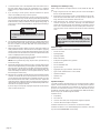
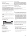
HEAVY-DUTY DIAMOND CORING EQUIPMENT
EXTRA ROBUSTE OUTILLAGE DE CAROTTAGE AU DIAMANT
EQUIPO DE PERFORACION CON PUNTAS DE DIAMANTE PARA TRABAJOS
PESADOS
OPERATOR'S MANUAL
MANUEL de L'UTILISATEUR
MANUAL del OPERADOR
TO REDUCE THE RISK OF INJURY, USER MUST READ AND UNDERSTAND OPERATOR'S MANUAL.
AFIN DE RÉDUIRE LE RISQUE DE BLESSURES, L'UTILISATEUR DOIT LIRE ET BIEN COMPRENDRE LE
MANUEL DE L'UTILISATEUR.
PARA REDUCIR EL RIESGO DE LESIONES, EL USUARIO DEBE LEER Y ENTENDER EL MANUAL DEL
OPERADOR.
DYMODRILLS
FOREUSES DYMODRILL
DYMODRILLS
Cat. No. 4004 20A
Cat. No. 4005 20A
Cat. No. 4079 20A
Cat. No. 4090 15A
Cat. No. 4092-20 15A
Cat. No. 4094 20A
Cat. No. 4096 20A
Cat. No. 4097-20 15A
DYMORIGS
OUTILLAGE DYMORIG
DYMORIGS
Cat. No. 4115 Small base
Petite base
Base pequeña
Cat. No. 4125 Small base
Petite base
Base pequeña
Cat. No. 4120 Large base
Grande base
Base grande
Cat. No. 4130 Large base
Grande base
Base grande

page 2
GENERAL SAFETY RULES — FOR ALL POWER TOOLS
WORK AREA SAFETY
ELECTRICAL SAFETY
PERSONAL SAFETY
POWER TOOL USE AND CARE
SERVICE
4. Power tool plugs must match the outlet. Never modify the plug in
any way. Do not use any adapter plugs with earthed (grounded)
power tools. Unmodifi ed plugs and matching outlets will reduce risk
of electric shock.
5. Avoid body contact with earthed or grounded surfaces such as
pipes, radiators, ranges and refrigerators. There is an increased risk
of electric shock if your body is earthed or grounded.
6. Do not expose power tools to rain or wet conditions. Water entering
a power tool will increase the risk of electric shock.
7. Do not abuse the cord. Never use the cord for carrying, pulling, or
unplugging the power tool. Keep cord away from heat, oil, sharp
edges, or moving parts. Damaged or entangled cords increase the
risk of electric shock.
8. When operating a power tool outdoors, use an extension cord suit-
able for outdoor use. Use of a cord suitable for outdoor use reduces
the risk of electric shock.
WARNING!
READ ALL INSTRUCTIONS
Failure to follow all instructions listed below may result in electric shock, fi re and/or serious injury. The term "power tool" in all of the warn-
ings listed below refers to your mains-operated (corded) power tool or battery-opearted (cordless) power tool.
SAVE THESE INSTRUCTIONS
16. Do not force the power tool. Use the correct power tool for your
application. The correct power tool will do the job better and safer at
the rate for which it was designed.
17. Do not use the power tool if the switch does not turn it on and off.
Any power tool that cannot be controlled with the switch is dangerous
and must be repaired.
18. Disconnect the plug from the power source and/or the battery pack
from the power tool before making any adjustments, changing ac-
cessories, or storing power tools. Such preventive safety measures
reduce the risk of starting the tool accidentally.
19. Store idle power tools out of the reach of children and do not al-
low persons unfamiliar with the power tools or these instructions
to operate power tools. Power tools are dangerous in the hands of
untrained users.
20. Maintain power tools. Check for misalignment or binding of moving
parts, breakage of parts and any other condition that may affect the
power tool's operation. If damaged, have the power tool repaired
before use. Many accidents are caused by poorly maintained power
tools.
21. Keep cutting tools sharp and clean. Properly maintained cutting
tools with sharp cutting edges are less likely to bind and are easier to
control.
22. Use the power tool, accessories and tool bits etc., in accordance
with these instructions and in the manner intended for the particu-
lar type of power tool, taking into account the working conditions
and the work to be performed. Use of the power tool for operations
different from those intended could result in a hazardous situation.
23. Have your power tool serviced by a qualifi ed repair person using
only identical replacement parts. This will ensure that the safety of
the power tool is maintained.
1. Keep work area clean and well lit. Cluttered or dark areas invite ac-
cidents.
2. Do not operate power tools in explosive atmospheres, such as
in the presence of fl ammable liquids, gases, or dust. Power tools
create sparks which may ignite the dust or fumes.
3. Keep children and bystanders away while operating a power tool.
Distractions can cause you to lose control.
9. Stay alert, watch what you are doing and use common sense when
operating a power tool. Do not use a power tool while you are tired
or under the infl uence of drugs, alcohol or medication. A moment
of inattention while operating power tools may result in serious personal
injury.
10. Use safety equipment. Always wear eye protection. Safety equip-
ment such as dust mask, non-skid safety shoes, hard hat, or hearing
protection used for appropriate conditions will reduce personal inju-
ries.
11. Avoid accidental starting. Ensure the switch is in the off-position
before plugging in. Carrying tools with your fi nger on the switch or
plugging in power tools that have the switch on invites accidents.
12. Remove any adjusting key or wrench before turning the power
tool on. A wrench or a key left attached to a rotating part of the power
tool may result in personal injury.
13. Do not overreach. Keep proper footing and balance at all times. This
enables better control of the power tool in unexpected situations.
14. Dress properly. Do not wear loose clothing or jewellery. Keep your
hair, clothing and gloves away from moving parts. Loose clothes,
jewellery, or long hair can be caught in moving parts.
15. If devices are provided for the connection of dust extraction and
collection facilities, ensure these are connected and properly used.
Use of these devices can reduce dust-related hazards.

page 3
1. Hold power tools by insulated gripping surfaces when performing
an operation where the cutting tool may contact hidden wiring or
its own cord. Contact with a "live" wire will make exposed metal parts
of the tool "live" and shock the operator.
2. Wear ear protectors with impact drills. Exposure to noise can cause
hearing loss.
3. Use auxiliary handles supplied with the tool. Loss of control can
cause personal injury.
4. Maintain tools carefully. Keep handles dry, clean and free from oil
and grease. Keep cutting edges sharp and clean. Follow instructions
for lubricating and changing accessories. Periodically inspect tool
cords and extension cords for damage. Have damaged parts repaired
or replaced by a MILWAUKEE service facility.
5. Maintain labels and nameplates. These carry important information.
If unreadable or missing, contact a MILWAUKEE service facility for a
free replacement.
6. WARNING! Some dust created by power sanding, sawing, grinding,
drilling, and other construction activities contains chemicals known to
cause cancer, birth defects or other reproductive harm. Some examples
of these chemicals are:
• lead from lead-based paint
• crystalline silica from bricks and cement and other masonry products,
and
• arsenic and chromium from chemically-treated lumber.
Your risk from these exposures varies, depending on how often you do
this type of work. To reduce your exposure to these chemicals: work
in a well ventilated area, and work with approved safety equipment,
such as those dust masks that are specifi cally designed to fi lter out
microscopic particles.
7. Always use anchor bolts to secure the base on cracked, uneven,
porous or vertical surfaces.
8. Diamond coring equipment requires the use of water. Since the use
of electrical equipment in wet areas is hazardous, the equipment must
be grounded (see "Grounding"). Wear insulated footwear and gloves
for extra protection against shock hazards.
9. Provide proper protection for people and property below the coring
area when coring through fl oors.
10. A meter box must always be used with Diamond Coring Equipment
so that amperage can be monitored. See "Accessories".
SPECIFIC SAFETY RULES
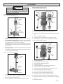
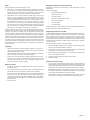
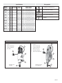
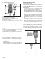
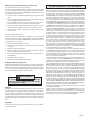
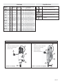
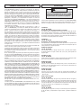
FUNCTIONAL DESCRIPTION
6
7
1
2
3
4
5
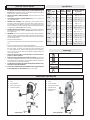
1. Twist-lock plug
2. Cord
3. Gear/shiftlever
4. Water shut-off valve
5. Threaded spindle
1. Twist-lock plug
2. Cord
3. Gear shift lever
4. Water shut-off valve
5. Spindle sleeve
6. Retaining ring
7. Shear pin
Clutch model
Shear pin model
1
2
3
4
5
Specifi cations
Catalog
No.
4004
4005
4079
4090
4092-20
4094
4096
4097-20
Amps
20
20
20
15
15
20
20
15
Volts
120
120
120
120
120
120
120
120
Motor
Protection
Clutch
Clutch
Shear Pin
Shear Pin
Clutch
Shear Pin
Clutch
Clutch
Speed
(RPM)
Low - 300
High - 600
Low - 600
High - 1200
Low - 300
High - 600
Low - 375
High - 750
Low - 375
High - 750
Low - 450
High - 900
Low - 450
High - 900
Low - 500
High - 1000
Suggested
Diameters in Medium
Aggregate
Low - 7" - 14"
High - 4" - 7"
Low - 4" - 7"
High - 3/4" - 4"
Low - 7" - 14"
High - 4" - 7"
Low - 5" - 8"
High - 2-1/2" - 5"
Low - 5" - 8"
High - 2-1/2" - 5"
Low - 6" - 10"
High - 2" - 6"
Low - 6" - 10"
High - 2" - 6"
Low - 3" - 5"
High - 1-1/4" - 3"
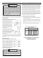
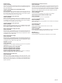
Amperes
Symbology
Canadian Standards Association
Underwriters Laboratories, Inc.
Volts Alternating Current
No Load Revolutions per Minute (RPM)

page 4
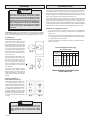
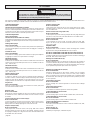
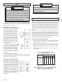
Grounded tools require a three wire extension cord. Double insulated tools
can use either a two or three wire extension cord. As the distance from the
supply outlet increases, you must use a heavier gauge extension cord. Us-
ing extension cords with inadequately sized wire causes a serious drop in
voltage, resulting in loss of power and possible tool damage. Refer to the
table shown to determine the required minimum wire size.
The smaller the gauge number of the wire, the greater the capacity of the
cord. For example, a 14 gauge cord can carry a higher current than a 16
gauge cord. When using more than one extension cord to make up the total
length, be sure each cord contains at least the minimum wire size required. If
you are using one extension cord for more than one tool, add the nameplate
amperes and use the sum to determine the required minimum wire size.
Guidelines for Using Extension Cords
• If you are using an extension cord outdoors, be sure it is marked with
the suffi x “W-A” (“W” in Canada) to indicate that it is acceptable for
outdoor use.
• Be sure your extension cord is properly wired and in good electrical
condition. Always replace a damaged extension cord or have it repaired
by a qualifi ed person before using it.
• Protect your extension cords from sharp objects, excessive heat and
damp or wet areas.
GROUNDING EXTENSION CORDS
Improperly connecting the grounding wire can result
in the risk of electric shock. Check with a qualifi ed
electrician if you are in doubt as to whether the outlet
is properly grounded. Do not modify the plug provided
with the tool. Never remove the grounding prong from
the plug. Do not use the tool if the cord or plug is dam-
aged. If damaged, have it repaired by a MILWAUKEE
service facility before use. If the plug will not fi t the
outlet, have a proper outlet installed by a qualifi ed
electrician.
Nameplate
Amperes
0 - 5
5.1 - 8
8.1 - 12
12.1 - 15
15.1 - 20
Extension Cord Length
25'
16
16
14
12
10
75'
16
14
12
10
10
100'
14
12
10
10
--
150'
12
10
--
--
--
200'
12
--
--
--
--
Recommended Minimum Wire Gauge
for Extension Cords*
* Based on limiting the line voltage drop to fi ve
volts at 150% of the rated amperes.
50'
16
16
14
12
10
READ AND SAVE ALL INSTRUCTIONS
FOR FUTURE USE.
WARNING!
Grounded Tools:
Tools with Three Prong Plugs
Tools marked “Grounding Required”
have a three wire cord and three
prong grounding plug. The plug must
be connected to a properly grounded
outlet (See Figures A and B). If the
tool should electrically malfunction
or break down, grounding provides a
low resistance path to carry electricity
away from the user, reducing the risk
of electric shock.
The grounding prong in the plug is con-
nected through the green wire inside
the cord to the grounding system in
the tool. The green wire in the cord
must be the only wire connected to
the tool's grounding system and must
never be attached to an electrically
“live” terminal.
Your tool must be plugged into an
appropriate outlet, properly installed
and grounded in accordance with all
codes and ordinances. The plug and
outlet should look like those in Figures
A and B.
Fig. B
MILWAUKEE Dymodrills are provided with a 20 amp locking plug (NEMA
L5-20). MILWAUKEE meter boxes may be provided with either a 20 amp
locking or a 30 amp (NEMA L5-30) locking plug depending on the model .
Double Insulated Tools:
Tools with Two Prong Plugs
Tools marked “Double Insulated” do
not require grounding. They have a
special double insulation system which
satisfies OSHA requirements and
complies with the applicable standards
of Underwriters Laboratories, Inc., the
Canadian Standard Association and
the National Electrical Code. Double
Insulated tools may be used in either
of the 120 volt outlets shown in Figures
C and D.
Fig. C
Fig. D
WARNING!
To reduce the risk of injury, always use a Ground Fault
Circuit Interrupter (GFCI) with diamond coring equip-
ment to reduce the risk of shock hazards. Always
position the GFCI as close as possible to the power
source.
Fig. A

page 5
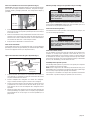
Fig. 4
Socket
screw
Ammeter
gauge
Meter
box
Socket screw
and washer
Cradle
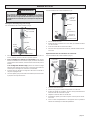
Moving the Handle to the Other Side
For Cat. Nos. 4125 & 4130 only (Fig. 3).
WARNING!
TOOL ASSEMBLY
To reduce the risk of injury, always unplug tool before
attaching or removing accessories or making adjust-
ments. Use only specifi cally recommended accesso-
ries. Others may be hazardous.
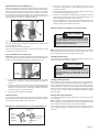
Assembling Dymorigs & Vac-U-Rig® Stands
For Cat. No. 4125 & 4130 only (Fig. 1).
1. Set the base on the ground. Loosen the hex bolt and nut (wrench not
supplied). Raise the column upright.
2. To core vertically or horizontally, insert the large column bolt (provided
in separate accessory bag) through the bottom of column and into the
base. Tighten hex bolt and nut (wrench not supplied).
To angle core, tilt the column to the desired angle and tighten the
hex bolt and nut. Save the column bolt for future use when vertical or
horizontal coring.
3. Tighten the two (2) black socket set screws located on the base with
the supplied wrench.
4. Screw the four (4) handle spokes (provided in separate accessory bag)
into the hub on the cradle assembly.
For Cat. No. 4115 & 4120 only (Fig. 2).
1. Set the base on the ground.
2. Remove two (2) bolts and two (2) lockwashers from accessory bag.
3. Place the column in the slot of the base.
4. Insert two (2) bolts and two (2) lockwashers and tighten securely.
Fig. 2
Cradle as-
sembly
Handle
spoke
Column
Base
Leveling
screws (4)
Column
bolts (2)
Lock washers
Fig. 3
Socket
screws (4)
Bubble
level
Socket
screw
Ammeter
gauge
Meter
box
Cradle
lock
Cradle
1. Tighten the cradle lock.
2. Loosen the socket head screw and remove the meter box.
3. Remove four (4) socket head screws holding the spoked handle hous-
ing.
4. Turn the assembly around 180°.
5. Replace the four (4) socket head screws and tighten securely.
6. Attach meter box to opposite side (see "Mounting the Meter Box").
For Cat. Nos. 4115 & 4120 only (Fig. 4).
1. Loosen the cradle lock.
2. Raise the cradle to the maximum height.
3. Lift the cradle an additional 1/2" by hand.
4. Tighten the cradle lock.
5. Loosen the socket head screw and remove the meter box.
6. Remove the meter box stud from the cradle.
7. Remove the screw and washer from the end of the pinion shaft.
8. Remove the handle and pinion shaft assembly.
9. Turn the assembly around 180° and insert into cradle.
10. Replace the screw and washer and tighten securely.
11. Replace the meter stud on the side opposite the handle.
12. Attach meter box to opposite side (see “Mounting the Meter Box”).
13. Loosen the cradle lock and lower the cradle until the pinion engages
the rack.
14. Tighten the cradle lock.
Fig. 1
Handle
spoke
Cradle
assembly
Column
Base
Leveling
screws (4)
Column bolts
Socket set
screws (2)
Hex bolt

page 6
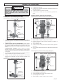
Adjusting the Gib Screws (Fig. 7)
After the motor is mounted, make sure the cradle and motor are rigid against
the column to prevent the motor or bit from wobbling during coring. Before
coring, try to wiggle the cradle with your hands. If the cradle is secure, it
should not move. If it does move, tighten the six (6) gib screws that secure
the cradle to the column as follows.
Fig. 7
Gib
Screws
Copper
Washer
Fig. 8
Water
Control
Valve
1. To install a bit, grease the spindle and bit threads to prevent corrosion
and to help prevent the bit from seizing on the threaded spindle.
2. Slip one copper washer (provided in separate accessory bag with the
water shut-off valve components) onto the threaded spindle against
the spindle shoulder. The bag should contain an extra copper washer;
save it for future use.
3. Thread the bit securely onto the threaded spindle.
Selecting Speeds
Dymodrills operate in either high or low gear. Use low speed for large diam-
eter bits and high speed for small diameter bits (see "Specifi cations").
Selecting and Installing a Core Bit (Fig. 8)
MILWAUKEE offers both standard and premium Dymobits designed to cut
through a variety of materials including poured concrete, steel-reinforced
concrete, and prestressed concrete. Always use clean, sharp bits.
For Cat. No. 4125 & 4130 only.
Tighten the six (6) gib screws with the hex wrench (supplied in a separate
accessory bag).
For Cat. No. 4115 & 4120 only.
To tighten the six (6) gib screws: loosen the hex nuts, tighten the screws
and then tighten the hex nuts.
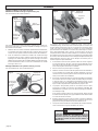
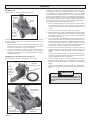
Mounting the Dymodrill Motor to the Stand
For All Cat. Nos. (Fig. 5 & 6).
Dymorigs include a mounting bracket which mounts Dymodrill motors to
the stand. An optional spacer assembly is available (see "Accessories"),
which can be used when coring with any bits; but it must be used with any
bit over 10" (outside diameter).
1. To mount the motor, loosen the cradle lock. Raise the cradle on the
column using the spoked handle to allow room for installing the bit later.
Tighten the cradle lock.
NOTE: If the cradle is diffi cult to move on the column, loosen the gib
screws (see "Adjusting the Gib Screws").
2. Fasten the mounting bracket or the optional spacer assembly to the
Dymodrill (Fig. 5) motor using the four (4) 1/4"-20 threaded socket
head screws and four (4) lock washers (they are the smaller of the two
provided in separate accessory bag). Make sure the square key on
the mounting bracket or spacer assembly engages with the slot on the
Dymodrill motor.
3. Fasten the mounting bracket (or optional spacer assembly) and
motor assembly to the cradle slot (Fig. 6) by inserting the four (4)
3/8"-16 threaded socket head cap screws and lock washers (they
are the larger of the two provided in separate accessory bag) through
the cradle. Place screws through the holes from the other side of the
Dymorig and place lock washers on the side of the mounting bracket.
After the Dymodrill motor is mounted, make sure the cradle is rigid against
the column to prevent the motor or bit from wobbling during coring. Before
coring, try to wiggle the cradle and motor with your hands. If the cradle is
secure, it should not move. If it does move, tighten the gib screws that secure
the cradle to the column (see "Adjusting the Gib Screws").
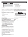
Mounting the Meter Box
For All Catalog Nos. (Fig. 3 & 4).
A meter box is standard equipment with the Vac-U-Rig
®
, but it must be
purchased separately for other Dymorigs (see "Accessories"). Attach the
meter box to the cradle on the side opposite of the handle.
1. Slip the collar on the meter box over the stud on the cradle.
2. Position the meter box as desired and tighten the 1/4"-20 threaded
socket head screw.
NOTE: For horizontal (wall) coring, the ammeter gauge must face
upward in view of the operator. Otherwise, water fl ow from the water
shut-off valve might drip into the outlets on the meter box.
Slot
Fig. 6
Fig. 5

page 7
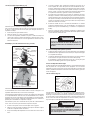
Leveling
Screws
Vacuum Line Coupler
Vacuum
Pad
Vacuum
Pad Stud
Vacuum Pad Nut
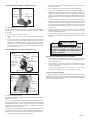
Fig. 12
Securing the Equipment to the Work Surface - Using an Expansion-Type
Anchor (Fig. 10)
For Catalog No. 4125 & 4130 only.
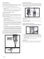
Assembling the Water Shut-Off Valve to the Dymodrill (Fig. 9)
Methods for Securing Equipment to Work Surface
NOTE: Some building materials contain steel reinforcements.
MILWAUKEE Dymobits can cut through embedded steel, but are not recom-
mended for coring solid steel plates.
Horizontal Coring (walls)
For specifi c instructions on using anchors, see "Using an Expansion-Type
Anchor".
Vertical Coring (fl oors)
Two methods will work to secure the rig for vertical coring: either an expan-
sion-type anchor OR a vacuum pump and vacuum pad system. Securing
the rig with an anchor gives better bit performance because the attachment
is more rigid. For specifi c instructions on assembling the vacuum system,
see "Assembling and Using a Vacuum System".
Optional Telescoping Assembly
The telescoping assembly can be used to supplement either securing
method.
NOTE: Vac-U-Rig
®
Cat. No. 4136 includes a vacuum pump and vacuum pad.
However, for some applications, you may choose to use an expansion-type
anchor to secure the tool.
Anchors and Telescoping Assembly are not supplied with any of the above
rigs. Telescoping Assembly can be purchased separately (see “Accesso-
ries”). Anchors unavailable through MILWAUKEE.
Fig. 9
Attach to
Dymodrill
Hose nut
Rubber
washer
Shut-off
valve
Hose adapter
1. Remove the water shut-off valve components from the accessory bag.
(The copper washers inside the bag are for bit installation.)
2. Insert the hose adapter into the hose nut. Then insert the rubber washer
into the hose nut.
3. Insert the hose nut assembly into the shut-off valve and securely tighten
the assembly with the supplied socket wrench; some threads on the
hose adapter will still be exposed.
4. Screw the shut-off valve assembly into the water swivel housing on the
Dymodrill motor (Fig. 8). Hand-tighten the assembly and then tighten it
approximately 1/4 turn with an adjustable wrench (not provided).
WARNING!
WARNING!
To reduce the risk of injury always secure the rig to
the work surface to help prevent personal injury and
to protect the rig. An unsecured rig could rotate during
coring and possibly cause injury.
To reduce the risk of injury always use an expansion-
type anchor during horizontal coring. Vacuum systems
can slip when used on a vertical surface.
OPERATION
Use a 5/8" expansion-type anchor (not supplied) that will accept a 5/8"
threaded rod or bolt to secure the base to the work surface.
1. Level the stand with the four (4) leveling screws using the bubble level
as a guide. When the stand is level, tighten the four (4) nuts on the
leveling screws.
2. Using an expansion-type anchor, insert a threaded rod or bolt through
the slot located on the base of the Dymorig and tighten the bolt or
washer and nut fi rmly in the anchor following the anchor manufacturer's
instructions.
Assembling and Using a Vacuum System (Fig. 11 & 12)
For Catalog No. 4115, 4125 & 4130 only.
Leveling
Screws
Rod or Bolt
Nut & Washer
or Vacuum
Pad Nut
Fig. 10
Coupler
Vacuum Release
Valve
Filter Jar
Vacuum
Gauge
Small Hole for At-
taching Pump to
Dymorig Stand
Vacuum Hose
Fig. 11

page 8
Leveling
Screws
Rod or Bolt
Fig. 13
WARNING!
The vacuum gauge must read a minimum of 20 inches
of mercury vacuum. To reduce the risk of injury DO
NOT CORE if the gauge reads less than 20 inches of
mercury vacuum.
One vacuum pad is supplied with the Vac-U-Rig
®
and they can be purchased
separately for other Dymorigs. The vacuum pad is most effective when it
is secured to a relatively smooth surface such as poured concrete. If the
surface is too porous or rough, the pad may not hold securely. Before us-
ing a vacuum pad, always check the gasket on the underside of the pad
to make sure it isn't worn, cracked or torn. If it is, immediately replace the
gasket, otherwise the vacuum pad may not hold the rig securely. To replace
the gasket, see "Replacing Vacuum Pad Gaskets" in the "Maintenance"
section. See "Accessories" for gasket part number.
1. To use the vacuum pad, tilt the base of the rig and slide the vacuum
pad under it so the threaded stud goes through the hole on the end of
the center slot on the base. Then set the stand upright.
2. Position the rig as required for coring the hole.
3. Level the rig with the four (4) leveling screws using the bubble level
(4125 & 4130 only) as a guide. When the rig is level, tighten the four
(4) nuts (4125 & 4130 only) on the leveling screws.
4. Connect one end of the supplied vacuum hose to the vacuum line
coupler on the vacuum pad. To do this, pull back the collar on the hose
and push the end of the hose onto the coupler until in snaps into place.
Then, connect the other end of the vacuum hose to the coupler on the
vacuum pump following the same procedure.
5. The vacuum pump may be set on a dry surface away from the rig or
mounted to the base of the Dymorig as shown. However, DO NOT
mount the vacuum pump to the Dymorig when angle coring.
To mount the vacuum pump on the Dymorig, place the small hole on
the vacuum pump mounting bracket over the vacuum pad stud on the
Dymorig.
6. Plug the vacuum pump into the power source—the pump will start
automatically. Step on the vacuum pad or the vacuum pad stud until
the vacuum pad lowers and adheres to the work surface.
7. After the pad is secured to at least 20 inches of mercury vacuum, tighten
the vacuum pad nut securely.
Using an Expansion-Type Anchor (Fig. 13)
For Cat. No. 4115 & 4120 only.
Use a 5/8" expansion-type anchor (not supplied) that will accept a 5/8"
threaded rod or bolt to secure the base to the work surface.
1. Remove the rubber gasket from the base.
2. Level the rig with the four (4) leveling screws.
3. Using an expansion-type anchor, insert a threaded rod or bolt through
the slot located in the base of the Dymorig and tighten the bolt or washer
and nut fi rmly in the anchor following the manufacturer's instructions.
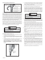
Assembling and Using a Vacuum System (Fig. 14 & 15)
WARNING!
The vacuum gauge must read a minimum of 20
inches of mercury vacuum. To reduce the risk of
injury DO NOT CORE if the gauge reads less than
20 inches of mercury vacuum.
Leveling
Screws
Vacuum
Line Cou-
pler
Vacuum Adapter Assembly
Fig. 15
Vacuum
Pad
Gasket
Coupler
Vacuum Release
Valve
Filter Jar
Vacuum
Gauge
Small Hole
for Attaching
Pump to Dym-
orig Stand
Vacuum Hose
Fig. 14
For Cat. No. 4120 only.
The vacuum pad is most effective when it is secured to a relatively smooth
surface such as poured concrete.
If the surface is too porous or rough, the vacuum pad may not hold securely.
Before using the vacuum pad, always check the gasket on the underside
of the base to make sure it isn't worn, cracked or torn. If it is, immediately
replace the gasket, otherwise the vacuum may not hold the rig securely.
To replace the gasket, see "Replacing Vacuum Pad Gaskets" in the "Main-
tenance" section. See “Accessories" for gasket part number.
1. Position the rig as required for coring the hole.
2. Loosen the four (4) leveling screws until the ends are above the bottom
surface of the base.
3. Place the vacuum adapter assembly into the slot in the base.
4. Connect one end of the supplied vacuum hose to the vacuum line
coupler on the vacuum base. To do this, pull back the collar on the
hose and push the end of the hose onto the coupler until it snaps into
place. Connect the other end of the vacuum hose to the coupler on the
vacuum pump following the same procedure.
5. The vacuum pump may be set on a dry surface away from the rig or
mounted to the base of the Dymorig as shown. To mount the vacuum
pump on the base, place the small holes on the vacuum pump mount-
ing bracket over the two tapped holes on the base. Attach the vacuum
pump to the base with two (2) 1/4" - 20 screws supplied in the accessory
bag.
6. Plug the vacuum pump into the power source - the pump will start
automatically. Step on the base until it lowers and adheres to the work
surface.
7. Tighten the four (4) leveling screws only enough to eliminate rock-
ing. Over-tightening can lift the gasket off the ground and release the
vacuum.

page 9
Water
Shut-Off
Valve
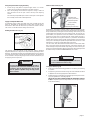
Fig. 18
Gear
Shift
Lever
To reduce the risk of injury, always check the work
area for hidden wires before coring.
Coring Procedure (Fig. 18)
1. Select and install a bit following guidelines in "Selecting and Installing
a Core Bit".
2. Secure the rig to the work surface using one of the methods described
in "Methods for Securing Equipment to Work Surface".
3. With the motor OFF, adjust the gear to either high or low speed accord-
ing to the guidelines in "Selecting Speeds".
NOTE: DO NOT SHIFT SPEEDS WHEN THE DYMODRILL MOTOR
IS ON. To adjust the speed on all Dymodrills, move the gear shift lever
to the desired setting.
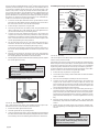
WARNING!
20 Amp Operat-
ing Range
15 Amp Operat-
ing Range
Fig. 16
Reading the Meter Box (Fig. 16)
The ammeter is the dial indicator on the meter box, which is standard
equipment with the Vac-U-Rig
®
and can be purchased separately for other
Dymorigs. The ammeter provides pressure feedback during coring, allowing
you to help prevent motor overload and premature bit wear. The green area
on the ammeter is the operating range and the red area indicates that you
are applying too much pressure.
Dymodrill Nos. 4079, 4090, and 4094 contain a shear pin to protect the gear
and motor against overload. This pin drives the spindle sleeve. If the bit binds,
the pin will shear to prevent gear and motor damage. Extra shear pins are
supplied with each Dymodrill and can be replaced (see "Accessories" for
part numbers). It is important to check the condition of the spindle before
using the tool each time. The spindle must be smooth without grooves or
pitting. If the spindle is not in good condition, it is possible for the threaded
spindle sleeve and the internal spindle to weld together and seize during
coring (see "Lubricating the Spindle for Dymodrills with a Shear Pin" in the
"Maintenance" section for spindle lubricating instructions).
Cat. Nos. 4004, 4005, 4092, 4096 and 4097 feature a friction clutch rather
than a shear pin to protect the motor and gears. If the motor overloads, the
clutch will begin to slip and the bit will stop rotating. The clutch is factory-set
and does not require adjustment. Nuisance (frequent) clutch slippage should
be addressed by an authorized MILWAUKEE service center.
Supply an Adequate Water Flow
An adequate supply of water must fl ow freely and constantly during the
entire cut. Dymodrills are equipped with a built-in water shut-off valve to
allow water to fl ow down the inside and up around the outside of the bit.
This acts to cool the bit and fl ush cuttings from the hole.
Using the Optional Telescoping Assembly
1. Secure the rig using either an expansion-type anchor or a vacuum
system (see "Securing the Equipment to the Work Surface").
2. Place the top fl ange of the extension against a ceiling or wall and
place the other end on the jack screw at the top of the Dymorig
column.
The assembly is adjustable up to 14 feet. Turn the jack screw to tighten
the assembly and to make small adjustments.
Fig. 17
Spindle Sleeve
(Shear pin models)
Threaded Spindle
(Clutch Models)
Shear Pin
Retaining Ring
(shear pin model only)
Shear Pin and Clutch (Fig. 17)
WARNING!
To reduce the risk of injury, always use Dymodrills in
conjunction with meter boxes. Meter Boxes provide
a switch to turn the Dymodrill motor OFF and ON
and an optimum operation range to help prevent
motor overload.

page 10
Diamond Coring
Factors that infl uence diamond core performance:
• Amount of coolant
• Dymorig rigidity
• Dymorig condition
• RPM of drill motor
• Feed pressure applied to bit by operator
• Amount of steel
• Size of embedded steel
• Age of concrete
• Aggregate (size, type, hardness, abrasiveness)
• Type of sand–manufactured vs. river (natural)
• Operator technique
• Operator care
• Bit runout
9. Monitor the water fl ow (see "Diamond Coring"). Generally, water should
fl ow at a rate of approximately one to two gallons per minute. If the water
fl ow is too heavy, the two holes in the water swivel housing will leak.
If that happens, reduce water fl ow. Water fl ow is adequate when the
water and cuttings are fl ushed in a circular pattern about 1/2" around
the bit. Keep the work area dry.
10. When the cut is complete, keep the drill motor ON and rotate the handle
clockwise to remove the bit. The bit may become stuck in the hole if
you turn the motor OFF before the bit is completely removed. Once the
bit is removed from the work surface, turn the motor OFF. Tighten the
cradle lock handle. Unplug the meter box from the power supply before
removing the vacuum pump to prevent accidental starting of the motor
when the vacuum pump is released.
If you are using a vacuum pump, unplug it and open the vacuum release
valve to release the vacuum.
4. Connect the water hose to the Dymodrill water shut-off valve and to
the water supply. Make sure the seal is watertight. Use a standard
garden hose if you require additional length. Set up a water collection
system.
5. If you are using a vacuum system, read the instructions for specifi c
setup in "Assembling & Using a Vacuum System".
Do not continue the following steps until the vacuum gauge reads at
least 20 inches of mercury vacuum. Never operate the Dymodrill if the
gauge reads less than 20 inches (see "Mothods for Securing Equipment
to Work Surface"). Always monitor the vacuum gauge during coring. If
water collects in the vacuum pump fi lter jar, empty it to prevent damage
to the pump.
To reduce the risk of injury, do not operate the Dym-
orig if the gauge reads less than 20 inches of mercury
vacuum.
Retrieving Cores and Deep Coring
When coring holes that are longer than the core bit, follow the steps be-
low.
1. Begin coring the hole as usual. When you have cored to the length of
the bit, stop the Dymodrill motor.
2. Remove the core by driving a chisel or slender wedge into the cut be-
tween the core and the work surface. You may also use a special core
tongs, bent wire or anchor bolts to remove the core.
3. After removing the core, reinsert the bit or use a bit extension and
continue coring (see "Accessories"). Removing cores with diameters
greater than twice their length can be diffi cult. One method to remove
such cores is to fi rst break the core into smaller pieces and then re-
move the pieces. Electric hammers and chisels are ideal for breaking
cores.
WARNING!
6. Turn the Dymodrill motor ON. Turn the water on so it fl ows freely through
the water shut-off valve (see "Supply an Adequate Water Flow"). Turn
the valve clockwise to increase water fl ow and counterclockwise to
decrease water fl ow.
7. While holding the handle, slightly loosen the cradle lock handle and
slowly rotate the handle to lower the bit into the workpiece, applying
steady, even pressure. To help reduce bit wandering, always use a light
load to start the hole and wait for the tip of the bit to penetrate the work
surface completely before increasing the load.
8. Use suffi cient pressure so the bit cuts constantly. Use the ammeter on
the meter box as a guide for proper pressure.
NOTE: If the rig shifts during coring, stop the motor, reposition the rig
and resume coring.
WARNING!
When coring through fl oors, cores generally drop
from the bit. To reduce the risk of injury, provide
proper protection for people and property below the
coring area.
Operator Technique
Core with consistent, fi rm feed pressure. Do not subject the bits to sudden
impacts. Uneven feed rate cracks diamonds. Low feed pressure polishes
diamonds, slows penetration and contributes to bit glazing. High feed
pressure can overload the drill motor or can cause diamonds to pull out
prematurely, particularly when coring embedded steel. Make the bit work,
but do not try to jam the bit through the material.
If vibration occurs:
1. Stop drilling.
2. Turn motor off.
3. Check for loose bolts, nuts and gib screws. Tighten if required.
4. Check for bit runout. Replace if required.
If vibration continues to occur, remove the core and loose material.
If vibration continues to occur after attempting these measures, return the
rig to the nearest MILWAUKEE service facility.

page 11
Equipment
• Make sure machinery is in good operating condition. The column, car-
riage, motor connection and base should all be fi rmly connected and
should not vibrate during coring.
• Motors should be of proper size (amperage and RPM) for the diameter
of the core bit used. Consult motor guide in catalog.
• Always make sure the Dymorig is rigidly mounted with an anchor or
vacuum; any movement or vibration will shorten the life of the core bit.
Standing on the rig's base as a form of anchoring is dangerous and
does not provide the necessary rigidity.
Diamond Core Bits
• For the fi rst 2 or 3 holes, use light feed pressure, so the new diamond
gradually breaks in.
• Lower the bit very slowly onto the work surface. Use light feed pressure
until the bit crown has penetrated or "seated" into the material.
• If the core bit encounters embedded steel, slow down the feed pressure
and let the bit core at its own pace. Don't force the bit. Typically the
water around the bit will clear when embedded steel is encountered.
Do not allow any vibration whatsoever or severe diamond breakage or
pullout will occur.
• Keep bits sharp.
Bit Glazing & Diamond Core Motor Shear Pins
Bit binding is caused by one of two things: a dull (glazed) bit or a poorly
stabilized rig.
Causes of bit glazing:
• Wrong RPM for bit diameter
• High feed pressure
• Low feed pressure
• High steel content in work surface
• Large, hard aggregate
• Too much water
• Low motor power
A sharp bit typically has good diamond exposure and will cut/grind almost
anything in its path, including embedded steel.
Sharpening Procedure for Core Bits
To work effi ciently, diamond core bits must maintain good diamond exposure.
Many factors work together to provide the "controlled erosion" cycle of the
tool's segment to occur. When this "controlled erosion" cycle is altered,
the bit can become dull or "glazed." Glazing becomes noticeable when the
coring feed rate slows dramatically or the bit does not cut. Examine the bit
immediately. If the diamonds are fl ush with the metal, they are underex-
posed or "glazed."
The following steps will often correct the problem:
1. Reduce water fl ow until it becomes very muddy. Continue using as little
water as possible until penetration increases.
2. If the bit does not open up, remove from hole. Pour into the kerf a thick
(1/4") layer of silica sand (the coarser the better).
3. Resume drilling for approximately 3 to 5 minutes with very little water
and at a lower RPM if possible.
4. Gradually increase water fl ow to fl ush sand from kerf.
5. Repeat as needed.
The Effects of Steel in Coring
• To self-sharpen, diamond-impregnated core bits require interaction
with an abrasive material. This abrasive material wears away the metal
composition in the segment's matrix. As this is done, sharp diamonds are
exposed and the grinding action created by the diamonds continues.
• Embedded metal (rebar) is not an abrasive material. It does not provide
the degree of abrasiveness required for matrix wear to occur and expose
sharp diamonds embedded in the segment's matrix.
• A high degree of exposure to embedded metal by the bit's segments
creates glazing. Glazing prevents the bit from cutting and coring.
Water
Water provides two main benefi ts during coring:
1. Water acts as a coolant, eliminating the heat caused by the friction of
the coring action. This preserves the integrity of the diamonds, the bond
matrix, the segment solder, and core tube. Without a coolant, the heat
buildup during coring can cause all of these components to fail.
2. Water fl ushes loose, abrasive particles created during coring. These
particles consist of aggregate, sand, diamond particles and various
metals from embedded steel and the core bit matrix. The hole must
be free of debris to allow the core bit to work. If loose particles are not
properly fl ushed from the hole, an unnecessary drag will occur along
the side of the core barrel. This can contribute to bit glazing through
lack of power as well as motor damage through amperage increases
due to bit resistance. In addition, loose particles tend to wear the bit
tube, which can eventually result in the loss of segments.
Monitor water fl ow. Water volume should be adjusted until water return is
a muddy, solid color. Clear water or clear streaks indicate too much water
volume. Excess water is a leading cause of bit glazing and failure. Other
factors contribute to glazing, but water adjustment is one of the most easily
controlled by the operator. Excessive water prevents adequate segment/
material contact. When the bit segments do not properly contact the work
surface, the desired "controlled erosion" effect which maintains bit sharp-
ness does not occur and the bit begins to glaze. This happens especially
with smaller diameter bits. Adequate water volume varies according to the
bit diameter. Use only enough water during coring to fl ush the cuttings from
the work surface.

page 12
Maintaining Tools
Keep your tool in good repair by adopting a regular maintenance pro-
gram. Before use, examine the general condition of your tool. Inspect
guards, switches, tool cord set and extension cord for damage. Check
for loose screws, misalignment, binding of moving parts, improper
mounting, broken parts and any other condition that may affect its safe
operation. If abnormal noise or vibration occurs, turn the tool off im-
mediately and have the problem corrected before further use. Do not
use a damaged tool. Tag damaged tools “DO NOT USE” until repaired
(see “Repairs”).
Under normal conditions, relubrication is not necessary until the motor
brushes need to be replaced. After six months to one year, depending on
use, return your tool to the nearest MILWAUKEE service facility for the
following:
• Lubrication
• Brush inspection and replacement
• Mechanical inspection and cleaning (gears, spindles, bearings,
housing, etc.)
• Electrical inspection (switch, cord, armature, etc.)
• Testing to assure proper mechanical and electrical operation
MAINTENANCE
Cleaning
Clean dust and debris from vents. Keep the tool handles clean, dry and
free of oil or grease. Use only mild soap and a damp cloth to clean your
tool since certain cleaning agents and solvents are harmful to plastics and
other insulated parts. Some of these include: gasoline, turpentine, lacquer
thinner, paint thinner, chlorinated cleaning solvents, ammonia and house-
hold detergents containing ammonia. Never use fl ammable or combustible
solvents around tools.
WARNING!
To reduce the risk of injury, always unplug
your tool before performing any maintenance. Never
disassemble the tool or try to do any rewiring on
the tool's electrical system. Contact a MILWAUKEE
service facility for ALL repairs.
WARNING!
To reduce the risk of injury, electric shock and damage
to the tool, never immerse your tool in liquid or allow
a liquid to fl ow inside the tool.
Lubricating Rack and Pinion
Maintain a light coat of MILWAUKEE Type "E" Grease on the rack and pinion
gears to reduce friction and wear.
Lubricating the Spindle for Dymodrills with a Shear Pin
Before each use, clean and lubricate the spindle or spindle sleeve with
MILWAUKEE Type "E" Grease to prevent the spindle from seizing during
coring.
1. To maintain the spindle on shear pin models, remove the retaining ring
with a screwdriver. Then remove the spindle sleeve.
2. Remove dust and debris from the inside and outside diameter of the
spindle and spindle sleeve and from the water hole in the spindle. Place
a light coating of MILWAUKEE Type "E" grease on the spindle.
3. Replace the spindle sleeve onto the spindle. Make sure the spindle
sleeve rotates freely on the spindle. Then replace the retaining ring.
Replacing Vacuum Pad Gaskets
For Cat. No. 4115, 4125 & 4130 only.
Through normal use, the rubber gaskets on the underside of the vacuum
pads can become worn, requiring replacement. If replacement is required,
take the pad to an authorized service center or replace the gasket as fol-
lows:
1. Remove the old gasket and thoroughly remove the old glue from the
groove.
2. Squeeze a continuous bead of rubber cement (Cat. No. 44-22-0060)
in the entire bottom of the groove.
3. Immediately place a new gasket (Cat. No. 43-44-0570) in the groove
and press fi rmly in place.
4. Turn the pad over and place the gasket side on a smooth fl at surface
and apply pressure to all edges of the pad.
5. Allow cement to dry for 24 hours before using.
For Cat. No. 4120 only.
With normal use, the rubber gasket on the underside of the base can become
worn, requiring replacement. If replacement is required, take the base to an
authorized service center or replace the gasket as follows:
1. Remove the motor and bit.
2. Tip the Dymorig on its back so that the wheels point down.
3. Remove the old gasket.
4. Squeeze a continuous bead of rubber cement (Cat. No. 44-22-0060)
in the entire bottom of the groove.
5. Place the new gasket (Cat. No. 43-44-0605) into the groove making
sure it is pushed in completely.
6. Stand the Dymorig upright again.
7. Reinstall the motor and bit.
Cleaning the Filter on the Vacuum Pump
Periodically clean the fi lter felts to keep the vacuum pump operating ef-
fi ciently. To clean the fi lter felts, remove the plastic jar and remove the felts
from the plastic tube. Remove dust and debris from the felts and clean the
plastic jar. Then replace the felts on the plastic tube and position the jar
onto the fi lter assembly.
Repairs
If your tool is damaged, return the entire tool to the nearest service cen-
ter.

page 13
FIVE YEAR TOOL LIMITED WARRANTY
Every MILWAUKEE power tool (including cordless product – tool, battery pack(s) and battery charger and Work Lights – cordless fl ashlights) is warranted
to the original purchaser only to be free from defects in material and workmanship. Subject to certain exceptions, MILWAUKEE will repair or replace any
part on an electric power tool which, after examination, is determined by MILWAUKEE to be defective in material or workmanship for a period of fi ve (5)
years* after the date of purchase. Return the electric power tool and a copy of proof of purchase to a MILWAUKEE factory Service Center location or
MILWAUKEE Authorized Service Station, freight prepaid and insured. This warranty does not apply to damage that MILWAUKEE determines to be from
repairs made or attempted by anyone other than MILWAUKEE authorized personnel, misuse, alterations, abuse, normal wear and tear, lack of mainte-
nance, or accidents.
*Every MILWAUKEE V™-technology (V18™ & V28™) LITHIUM-ION Battery Pack and M18 XC LITHIUM-ION Battery Pack is warranted for fi ve (5) years
/ 2000 charges from the date of purchase, whichever fi rst occurs. The fi rst 1000 charges or 2 years of the warranty, whichever fi rst occurs, are covered
through free replacement of the defective battery. This means that for the earlier of the fi rst 1000 charges or two (2) years from the date of purchase/fi rst
charge, a replacement battery will be provided to the customer for any defective battery free of charge. Thereafter, the remaining charges up to a total of
2000 or the remainder of the fi ve (5) year period from the date of purchase, whichever fi rst occurs, will be covered on a pro rata basis. This means that
every customer gets an additional 1000 charges or three (3) years of pro rata warranty on the V™-technology LITHIUM-ION Battery Pack and M18 XC
LITHIUM-ION Battery Pack depending upon the amount of use.
*The warranty period for ALL other LITHIUM-ION Battery Packs is two (2) years from the date of purchase.
*The warranty period for M12 2-Beam Laser & M12 Power Port, Ni-CD Battery Packs, Job Site Radios, and Trade Titan™ Industrial Work Carts is one (1)
year from the date of purchase.
Warranty Registration is not necessary to obtain the applicable warranty on a MILWAUKEE product. The manufacturing date of the product will be used
to determine the warranty period if no proof of purchase is provided at the time warranty service is requested.
ACCEPTANCE OF THE EXCLUSIVE REPAIR AND REPLACEMENT REMEDIES DESCRIBED HEREIN IS A CONDITION OF THE CONTRACT FOR THE
PURCHASE OF EVERY MILWAUKEE PRODUCT. IF YOU DO NOT AGREE TO THIS CONDITION, YOU SHOULD NOT PURCHASE THE PRODUCT.
IN NO EVENT SHALL MILWAUKEE BE LIABLE FOR ANY INCIDENTAL, SPECIAL, CONSEQUENTIAL OR PUNITIVE DAMAGES, OR FOR ANY COSTS,
ATTORNEY FEES, EXPENSES, LOSSES OR DELAYS ALLEGED TO BE AS A CONSEQUENCE OF ANY DAMAGE TO, FAILURE OF, OR DEFECT
IN ANY PRODUCT INCLUDING, BUT NOT LIMITED TO, ANY CLAIMS FOR LOSS OF PROFITS. THIS WARRANTY IS EXCLUSIVE AND IN LIEU OF
ALL OTHER WARRANTIES OR CONDITIONS, WRITTEN OR ORAL, EXPRESSED OR IMPLIED. WITHOUT LIMITING THE GENERALITY OF THE
FOREGOING, MILWAUKEE DISCLAIMS ANY IMPLIED WARRANTY OF MERCHANTABILITY OR FITNESS FOR A PARTICULAR USE OR PURPOSE,
AND ALL OTHER WARRANTIES.
This warranty applies to product sold in the U.S.A., Canada and Mexico only.
Please consult the ‘Service Center Search’ in the Parts & Service section of MILWAUKEE’s website www.milwaukeetool.com or call 1.800.SAWDUST
(1.800.729.3878) to locate your nearest service facility for warranty and non-warranty service on a Milwaukee electric power tool.

page 14
ACCESSORIES
WARNING!
To reduce the risk of injury, always unplug the tool before attaching or
removing accessories. Use only specifi cally recommended accessories.
Others may be hazardous.
Meter Boxes
Cat. No. 48-51-0100 (30 amp, 120 volt)
(Not available in Canada)
Same as supplied with Vac-U-Rig
®
Attachment Kit No. 49-22-7075 and with
Cat. No. 4136. Ammeter and power switch appear on the front panel and a
single 20 amp twist lock receptacle for the drill motor and two convenience
outlets are on the back of the box.
Meter Boxes
Cat. No. 48-51-0120 (20 amp, 120 volt)
(Can be used in Canada)
Ammeter and power switch appear on the front panel with a single 20 amp
twist lock receptacle for the drill motor on the back.
Telescoping Extension Assembly
Cat. No. 49-95-1000
This assembly braces the rig between the fl oor and ceiling for maximum
rigidity. It adjusts for 14-foot ceilings and features fi xed hole adjustments.
Copper Washer
Cat. No. 45-88-8565
Before using the tool, slip this washer onto the spindle to prevent the bit
from seizing on spindle during coring.
Spacer Assembly
Cat. No. 49-67-0110
For use with Cat. Nos. 4125 and 4130. Mounts between cradle and Dymodrill
motor when using 10" - 14" coring bits.
Spacer Assembly
Cat. No. 49-67-0115
For use with Cat. No. 4115 and 4120. Mounts between cradle and Dymodrill
motor when using 10" - 14" coring bits.
Water Collecting Ring
Cat. No. 48-70-0060
For use where water fl ow from coring must be trapped and drained. Dike-type
collector ring holds water for fast disposal when used with bits up to 10" in
diameter. A built-in vacuum hose fi tting also allows the ring to be used with
a wet/dry vacuum cleaner.
Water Hose
Cat. No. 49-18-0055
This 8-foot water hose features a 5/8" coupling and standard brass male
and female water hose fi ttings.
Water Tank
Cat. No. 49-76-0055
This 3-1/2 gallon heavy-duty, impact-resistant poly tank is for use where a
regular tap water supply is not available.
Vacuum Pad Assembly (Single Pad)
Cat. No. 49-22-7100
This single vacuum pad is the same as supplied with Vac-U-Rig
®
Attachment
Kit No. 49-22-7075. Can be used with Cat. Nos. 4115, 4125 and 4130.
Vacuum Pump Assembly (115 Volts)
Cat. No. 49-50-0160
This heavy-duty 1/8 H.P. pump comes complete with vacuum gauge, air
fi lter and cord. May be mounted to the base of the unit. Same as furnished
with Vac-U-Rig
®
49-22-7075. Can be used with Cat. Nos. 4115, 4125 and
4130.
Vacuum Pump Assembly (115 Volts)
Cat. No. 49-50-0165
This heavy-duty 1/8 H.P. pump comes complete with vacuum gauge, air
fi lter and cord. May be mounted to the base of the unit. Can be used with
Cat. No. 4120.
Vac-U-Rig® Attachment Kit (115 Volts)
Cat. No. 49-22-7065
This kit includes: (1) vacuum pad; (1) vacuum pump assembly with gauge,
fi lter, 8-foot air hose, and fi ttings. Can be used with Cat. No. 4120.
Vac-U-Rig® Attachment Kit
Cat. No. 49-22-7075
This kit includes: (1) vacuum pad; (1) vacuum pump assembly with gauge,
fi lter, 8-foot air hose, and fi ttings. Can be used with Cat. Nos. 4115, 4125
& 4130.
Threaded Adapter
Cat. No. 48-04-0160
Thread Adapter reduces the thread size of 1-1/4"-7 to 5/8"-11
MILWAUKEE Dymobits and extensions.
Shear Pin No. 44-60-0065 (Low Strength Shear Pin)
Shear Pin No. 44-60-0032* (High Strength Shear Pin)
* (Standard equipment on Dymodrills except clutch Cat. Nos. 4004, 4005,
4092, 4206 and 4097).
9" Bit Extension
Cat. No. 48-95-1500
Extension threaded on both ends with a 1-1/4"-7 thread. For use with Dia-
mond Core Bits over 2" in diameter and a 1-1/4"-7 thread. Extension mounts
directly to the Dymodrill. Two or more extensions can be used together to
core deep holes.
10-1/2" Bit Extension
Cat. No. 48-95-2100
Extension threaded on both ends with a 5/8"-11 thread. For use with 1-1/4"
and 1-1/2" diameter Diamond Core Bits with a 5/8"-11 thread. Extension
requires Threaded Adapter No. 48-04-0160 for mounting to Dymodrills. Two
or more extensions can be used together to core deep holes.
3/16" Socket Wrench
Cat. No. 49-96-0085
Use to mount Dymodrills onto the cradle on Dymorigs
1-3/8" Open End Wrench
Cat. No. 49-96-4700
Use to install bits onto Dymodrills.
Vacuum Pad Gasket
Cat. No. 43-44-0570
Replacement part for vacuum pads on Cat. Nos. 4115, 4125 & 4130
Vacuum Base Gasket
Cat. No. 43-44-0605
Replacement part for vacuum base Cat. No. 4120.
Rubber Cement
Cat. No. 44-22-0060
Use to bond vacuum pad gaskets to vacuum pads on Cat. Nos. 4115, 4120,
4125 and 4130.
Type "E" Grease
Cat. No. 49-08-4122
Use for lubricating rack and pinion as well as spindle.
For a complete listing of accessories refer to your MILWAUKEE Electric Tool catalog or go on-line to www.milwaukeetool.com. To obtain a
catalog, contact your local distributor or a service center.
Page is loading ...
Page is loading ...
Page is loading ...
Page is loading ...
Page is loading ...
Page is loading ...
Page is loading ...
Page is loading ...
Page is loading ...
Page is loading ...
Page is loading ...
Page is loading ...
Page is loading ...
Page is loading ...
Page is loading ...
Page is loading ...
Page is loading ...
Page is loading ...
Page is loading ...
Page is loading ...
Page is loading ...
Page is loading ...
Page is loading ...
Page is loading ...
Page is loading ...
Page is loading ...
Page is loading ...
Page is loading ...
Page is loading ...

58-14-3005d10 09/09 Printed in USA
MILWAUKEE ELECTRIC TOOL CORPORATION
13135 West Lisbon Road • Brookfi eld, Wisconsin, U.S.A. 53005
UNITED STATES
MILWAUKEE Service
CANADA
Service MILWAUKEE
MEXICO
Soporte de Servicio MILWAUKEE
MILWAUKEE prides itself in producing a premium quality
product that is NOTHING BUT HEAVY DUTY
®
. Your satisfaction
with our products is very important to us! If you encounter any
problems with the operation of this tool, or you would like to
locate the factory Service/Sales Support Branch or authorized
service station nearest you, please call...
MILWAUKEE est fi er de proposer un produit de première
qualité NOTHING BUT HEAVY DUTY
®
. Votre satisfaction est ce
qui compte le plus!
En cas de problèmes d’utilisation de l’outil ou pour localiser
le centre de service/ventes ou le centre d’entretien le plus
proche, appelez le...
416.439.4181
fax: 416.439.6210
Milwaukee Electric Tool (Canada) Ltd
755 Progress Avenue
Scarborough, Ontario M1H 2W7
Notre réseau national de distributeurs agréés se tient à
votre disposition pour fournir l’aide technique, l’outillage et
les accessoires nécessaires. Composez le 416.439.4181
pour obtenir les noms et adresses des revendeurs les plus
proches ou bien consultez la section «Où acheter» sur notre
site web à l’adresse www.milwaukeetool.com
1-800-SAWDUST
(1.800.729.3878)
Monday-Friday
7:00 AM - 6:30 PM Central Time
or visit our website at
www.milwaukeetool.com
For service information, use the 'Service Center Search' icon
found in the 'Parts & Service' section.
Additionally, we have a nationwide network of authorized
Distributors ready to assist you with your tool and accessory
needs. Check your “Yellow Pages” phone directory under
“Tools-Electric” for the names & addresses of those nearest
you or see the 'Where To Buy' section of our website.
Contact our Corporate After Sales Service
Technical Support about ...
• Technical Questions
• Service/Repair Questions
• Warranty
call: 1-800-SAWDUST
fax: 1.800.638.9582
email: [email protected]
Register your tool online at www.milwaukeetool.com
and...
• receive important notifi cations regarding your purchase
• ensure that your tool is protected under the warranty
• become a HEAVY DUTY club member
Herramientas Alerka
Dr. Andrade 140 Local B, Col. Doctores
Delegación Cuauhtemoc, México D.F.
Telefono sin costo 01 800 832 1949
www.ttigroupmexico.com
Adicionalmente, tenemos una red nacional de distribuidores
autorizados listos para ayudarle con su herramienta y sus
accesorios. Por favor, llame al 01 800 832 1949 para obtener
los nombres y direcciones de los más cercanos a usted,
o consulte la sección ‘Where to buy’ (Dónde comprar) de
nuestro sitio web en www.ttigroupmexico.com
Registre su herramienta en línea, en
www.ttigroupmexico.com y...
• reciba importantes avisos sobre su compra
• asegúrese de que su herramienta esté protegida por la
garantía
• conviértase en integrante de Heavy Duty
-
 1
1
-
 2
2
-
 3
3
-
 4
4
-
 5
5
-
 6
6
-
 7
7
-
 8
8
-
 9
9
-
 10
10
-
 11
11
-
 12
12
-
 13
13
-
 14
14
-
 15
15
-
 16
16
-
 17
17
-
 18
18
-
 19
19
-
 20
20
-
 21
21
-
 22
22
-
 23
23
-
 24
24
-
 25
25
-
 26
26
-
 27
27
-
 28
28
-
 29
29
-
 30
30
-
 31
31
-
 32
32
-
 33
33
-
 34
34
-
 35
35
-
 36
36
-
 37
37
-
 38
38
-
 39
39
-
 40
40
-
 41
41
-
 42
42
-
 43
43
-
 44
44


Ask a question and I''ll find the answer in the document
Finding information in a document is now easier with AI
in other languages
- français: Milwaukee 4004 Manuel utilisateur
- español: Milwaukee 4004 Manual de usuario
Related papers
-
Milwaukee 4004 20A User manual
-
-
Milwaukee 4004 20A User manual
-
Milwaukee 4115 User manual
-
-
-
-
Milwaukee 2771-20 User guide
-
-
Other documents
-
Hilti 3423950 Operating instructions
-
Ancona AN-7171 Operating instructions
-
Diamond Products CB733 Operating instructions
-
Diamond CB744 Operating instructions
-
 Bluerock Tools 12"Z1/LRB/TS Operational Manual
-
-
-
-
-
