99043005H
3. Coloque la campana de tal manera que:
a.) Los alambres pasen por la abertura del agujero ciego.
b.) La mayor parte de las aberturas de ojo caben sobre los tornillos
de montaje de la campana.
c.) El conector de registro/ducto se desliza dentro del ducto (campanas
con ventilación de 3¼" x 10" (8.25 x 25.4 cm) solamente).
4. Coloque la campana para que su frente quede a ras con el marco del
mueble.
5. Apriete bien los tornillos de montaje de la campana.
ADVERTENCIA: TODAS LAS CONEXIONES ELECTRICAS
DEBEN HACERSE EN CONFORMIDAD CON LOS CODIGOS Y
REGULACIONES LOCALES O EL CODIGO ELECTRICO NACIO-
NAL. SI UD. NO ESTA FAMILIARIZADO CON LOS METODOS
DE INSTALACION DEL ALAMBRADO ELECTRICO, CONTRATE
LOS SERVICIONS DE UN ELECTRISTA CALIFICADO.
6. Complete el alambrado eléctrico en la caja de derivaciones
de acuerdo con los códigos vigentes y reemplace la caja.
Asegúrese que todos los alambres están dentro de la caja.
7. Instale un foco (75 vatios máximo).
8. Si la campana lleva ventilación, quite el taco de carbón del filtro.
Instale el filtro.
9. Conecte la electricidad y observe el funcionamiento del venti-
lador y la luz. Asegúrese que el registro funciona libremente.
USO Y CUIDADO
FILTRO DE ALUMINIO
Para mayor eficiencia el filtro de aluminio permanente deberá
sacarse y limpiarse periódicamente. Para limpiar el filtro debe
remojarse en agua caliente con detergente y lavarse completa-
mente. El filtro de aluminio puede lavarse en la lavadora de platos.
FILTRO COMBINACION
Este filtro debe examinarse periódicamente y cuando llega a
saturarse debe reemplazarse. No hay
una
manera efectiva de
reactivar este filtro.
LUCES
No emplee un foco de más de 75 vatios en un portafoco liviano.
CUIDADO DE LAS SUPERFICIES EXTERIORS
Limpie su campana utilizando un detergente suave recomendado
para superficies pintadas. NO USE TELAS ABRASIVAS, TACOS
DE LANA DE ACERO O POLVOS PARA FREGAR.
ADVERTENCIA: SIEMPRE DESCONECTE LA ELECTRICIDAD
ANTE DE HACER SERVICIO EN LA CAMPANA DE COCINA.
CUIDADO DEL MOTOR DEL VENTILADOR
El motor del ventilador lleva cojinetes sellados permanentes que
no requieren aceite bajo uso normal. Unas pocas gotas en cada
cojinete después de tres años de trabajo pesado alagarán la vida
del motor. Limpie el motor con un trapo húmedo y detergente quita-
grasa cuando vea que se ha acumulado una densa capa de grasa.
COMO EVITAR QUE OCURRA UN INCENDIO DEBIDO A LA GRASA QUE SE
ACUMULA EN UN EXTRACTOR COMUN
• Su extractor proporciona una barrera protectora entre la superficie para
cocinar y los gabinetes.
• Mantenga el abanico, los filtros y las superficies donde se acumula la grasa
LIMPIAS conforme a las instrucciones.
• ENCIENDA siempre el extractor cuando esté cocinando a fuego alto para
mantener el area para cocinar y el extractor limpios.
• Utilice las hornillas de fuego alto solamente cuando sea necesario.
• No deje las hornillas de la estufa sin atención cuando esté cocinando.
El vapor o el aceite que salpique puede ocasionar un incendio o
acumulación de humo.
• Siempre utilice los utensilios del tamaño adecuado.
• Si está preparando alimentos flameados, como las Cerezas a la Jubilee, EN-
CIENDA siempre el extractor en ALTO para evitar que el calor pueda causar
algún daño o un incendio.
COMO EXTINGUIR UN INCENDIO EN UN EXTRACTOR COMUN
• No levante nunca una sartén que esté en llamas. Si se le cae, las llamas se
pueden extender rapidamente.
•
¡
NO UTILICE AGUA PARA APAGARLO! Puede ocasionar una explosión de
vapor. Las toallas de cocina mojadas también son peligrosas.
• Ahogue las llamas con una tapa ajustada o una charola.
• Las llamas provocadas por la grasa también se pueden apagar con bicarbonato
de sodio o un extinguidor químico.
• Apague las hornillas - si puede hacerlo sin quemarse.
GARANTIA
626850
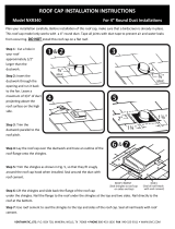
1
2
3
4
5
7
6
LISTA DE REPUESTOS
Clave N
o.
Pieza N
o.
Descripción
1 97016971 Interruptor de Ventilador – Blanco (incluye interruptor de la luz)
97016972 Interruptor de Ventilador – Almendra (incluye interruptor de la luz)
97016970 Interruptor de Ventilador – Negro (incluye interruptor de la luz)
97016973 Interruptor de Ventilador – Beige (incluye interruptor de la luz)
2 97016971 Interruptor de la Luz – Blanco (incluye interruptor de ventilador)
97016972 Interruptor de la Luz – Almendra (incluye interruptor de ventilador)
97016970 Interruptor de la Luz – Negro (incluye interruptor de ventilador)
97016973 Interruptor de la Luz – Beige (incluye interruptor de ventilador)
3 R730088 Conjunto de Motor/Aspa
4 R610045 Filtro de Aluminio (uso con extractor ducto solamente)
* R610050 Filtro - Sin Ducto
* R610051 Tacos de Filtro – Sin Ducto
5 R566088 Portafoco
6 99091020 Cubierta de Venteada - Blanco
99091021 Cubierta de Venteada - Almendra
99091022 Cubierta de Venteada - Negro
99091027 Cubierta de Venteada - Beige
7 R6689601 Cubierta para la Conexion Electrica - Blanco
R6689602 Cubierta para la Conexion Electrica - Almendra
R6689604 Cubierta para la Conexion Electrica - Negro
R6689605 Cubierta para la Conexion Electrica - Beige
* No ilustrado. Compre por separado.
Las piezas de repuestos
se pueden pedir en
nuestro website en
www.Broan.com
GARANTIA BROAN-NUTONE LIMITADA POR UN AÑO
Broan-NuTone garantiza al consumidor comprador original de sus productos que dichos productos carecerán de defectos en
materiales o en mano de obra por un período de un año a partir de la fecha original de compra. NO EXISTEN OTRAS GARANTIAS,
EXPLICITAS O IMPLICITAS, INCLUYENDO, PERO NO LIMITADAS A, GARANTIAS IMPLICITAS DE COMERCIALIZACION O APTITUD
PARA UN PROPOSITO PARTICULAR.
Durante el período de un año, y a su propio criterio, Broan-NuTone reparará o reemplazará, sin costo alguno cualquier producto
o pieza que se encuentre defectuosa bajo condiciones normales de servicio y uso.
LA PRESENTE GARANTÍA NO CUBRE LOS TUBOS FLUORESCENTES NI SUS ARRANCADORES, BOMBILLAS DE HALÓGENO
E INCANDESCENTES, FUSIBLES, FILTROS, CONDUCTOS, TAPONES DE TECHO O PAREDES Y DEMÁS ACCESORIOS PARA
CONDUCTOS. Esta garantía no cubre (a) mantenimiento y servicio normales o (b) cualquier producto o piezas que hayan sido
utilizadas de forma errónea, negligente, que hayan causado un accidente, o que hayan sido reparadas o mantenidas inapropia-
damente (por otras compañías que no sean Broan-NuTone), instalación defectuosa, o instalación contraria a las instrucciones
de instalación recomendadas.
La duración de cualquier garantía implícita se limita a un período de un año como se especifica en la garantía expresa. Algunos
estados no permiten limitaciones en cuanto al tiempo de expiración de una garantía implícita, por lo que la limitación antes
mencionada puede no aplicarse a usted.
LA OBLIGACION DE BROAN-NUTONE DE REPARAR O REEMPLAZAR, SIGUIENDO EL CRITERIO DE BROAN-NUTONE, DEBERA
SER EL UNICO Y EXCLUSIVO RECURSO LEGAL DEL COMPRADOR BAJO ESTA GARANTIA. BROAN-NUTONE NO SERA
RESPONSABLE POR DAÑOS INCIDENTALES, CONSIGUIENTES, O POR DAÑOS ESPECIALES QUE SURJAN A RAIZ DEL USO O
DESEMPEÑO DEL PRODUCTO. Algunos estados no permiten la exclusión o limitación de daños incidentales o consiguientes,
por lo que la limitación antes mencionada puede no aplicarse a usted.
Esta garantía le proporciona derechos legales específicos, y usted puede también tener otros derechos, los cuales varían de estado
a estado. Esta garantía reemplaza todas las garantías anteriores.
Para calificar en la garantía de servicio, usted debe (a) notificar a Broan-NuTone al domicilio o al número de teléfono que se menciona
abajo, (b) dar el número del modelo y la identificación de la pieza, y (c) describir la naturaleza de cualquier defecto en el producto o
pieza. En el momento de solicitar servicio cubierto por la garantía, usted debe de presentar evidencia de la fecha original de compra.
Broan-NuTone LLC, 926 W. State Street, Hartford, Wisconsin 53027 www.broan.com 800-558-1711