Page is loading ...

Indoor/Outdoor/
Attic Stealth HD 200
Amplified Antenna
User’s Manual

2
WARNING: INSTALLATION OF
THIS PRODUCT NEAR POWER
LINES IS DANGEROUS, FOR
YOUR SAFETY, FOLLOW THE
INSTALLATION DIRECTIONS.
WATCH FOR WIRES! YOU CAN
BE KILLED IF THIS ANTENNA
COMES NEAR ELECTRIC POWER
LINES. READ INSTRUCTIONS!

3
TABLE OF CONTENTS
IMPORTANT SAFETY INSTRUCTIONS ....................................................4
SELECT AND MEASURE YOUR INSTALLATION SITE ......................... 5
CHOOSE A MOUNT TYPE ............................................................................6
ASSEMBLY INSTRUCTIONS - Parts List .................................................7
ASSEMBLY INSTRUCTIONS - Assembling the Antenna ................8
MOUNTING THE ANTENNA .......................................................................9
TELEVISION CONNECTION & CHANNEL SCANNING ...................10
ANTENNA GROUNDING AND CONNECTION ..................................10
ANTENNA REMOVAL ................................................................................. 14
ANTENNA HELPFUL TIPS .........................................................................14

4
IMPORTANT SAFETY INSTRUCTIONS:
• NEVER touch ANYTHING or ANYONE in contact with a
power line. You can be electrocuted. In case of an accident
or emergency, call 911 immediately for help.
• INSPECT your installation site carefully for power lines.
Make sure there is no possibility the antenna, its
mounting structure or your ladder can come into
contact with power lines. Be sure to consider what can go
wrong during installation.
• KEEP the distance between power lines and the antenna
and its mounting structure at least 2 times the combined
height of the antenna and mounting structure added
together. In the event the antenna falls, during or after
assembly, there must be sufficient distance to ensure it
does not come into contact with the power lines.
• KEEP your ladder, theantenna and antenna mounting
structure (such as mast, pole, and mount) far away from
power lines at all times.
• GROUND the antenna and the antenna mounting
structure in accordance with the NEC electrical
code, all state and local electrical code requirements
• COMPLETE the antenna assembly on the ground prior to
mounting.
• DO NOT use a metal ladder or install the antenna on a
windy day. If the antenna or mast starts to fall, allow it to
fall. Do not attempt to catch the antenna.
• EXERCISE caution when working on a roof.
• APPLY the danger label included to the base of the
antenna mounting structure.
• INFORM others of the danger of touching power lines or
touching other objects in contact with power lines.
• CONTACT a professional installer in your area to do the
antenna installation if you are unsure how to safely install
and ground this antenna.
• DO NOT use the power inserter and power supply
outdoors. They are rated for indoor use only. Use only the
power supply provided with the antenna.

5
SELECT AND MEASURE YOUR INSTALLATION SITE
Key things to consider in choosing the antenna installation
site are:
1) Choose a SAFE location that is far away from power lines.
Keep the distance between power lines and the
antenna and its mounting structure at least 2 times the
combined height of the antenna and its mounting structure
added together. Refer to the Important Safety
Instructions.
2) Determine the location of the broadcast towers in your
area. You will need to point the small end of your antenna
toward those towers. There are online resources such as
www.antennaweb.org that can help you identify
the location of your local broadcast towers and
the channels you can expect to receive.
3) Check your local, city and state building and electrical
codes. Make sure your planned installation is safe and in
compliance with all applicable codes, rules and
regulations.

6
CHOOSE A MOUNT TYPE:
Some examples of common mounting options are shown
below.
1) Indoor Wall Mount:
2) Outdoor Wall Mount:
(under eave)
3) Attic Mount:
4) Existing Pole Mount:
IF YOU ARE UNSURE OR DO NOT FEEL CAPABLE
OF INSTALLING THIS ANTENNA, CONTACT
A PROFESSIONAL INSTALLER IN YOUR AREA.

7
ASSEMBLY INSTRUCTIONS:
Thank you for purchasing the GE 34560 Stealth 200 HD
Amplified Antenna. This antenna is a sturdy, high-performing
antenna designed to receive UHF and VHF broadcasted
signals. The small, compact design allows you to install the
antenna almost anywhere.
PARTS LIST:
1) Antenna Main Body 1 ea.
2) Antenna End Caps 2 ea.
3) Monopoles with Lock Washers 4 ea.
4) Power Inserter 1 ea.
5) Rubber Boot 1 ea.
6) Mounting Bracket 1 ea.
7) 15mm Bracket Screws 4 ea.
8) U-Bolts 2 ea.
a. Wing Nuts 4 ea.
b. Washers 4 ea.
9) 27mm Mounting Screws 4 ea.
10) Wall Anchors 4 ea.
11) Zip Tie 1 ea.
12) Coax Cable 1 ea.
13) Power Supply 1 ea.

8
ASSEMBLING THE ANTENNA:
1) Attach Monopoles to Antenna Main Body:
a) Take provided Monopoles and Lock Washers and
screw in sides of Antenna Main Body. Make sure that
all four Monopoles are tightly secured.
2) Attach Antenna End Caps to Antenna Main Body:
a) Take the provided Antenna End Caps and screw them
on each side of the Antenna Main Body (see note below):
NOTE: The Antenna End Caps are there to protect the
Monopoles from any outside elements. Make sure the
Antenna End Caps are secured tightly to each end of
the Antenna Main Body but not so tight that the
grooves become stripped.

9
3) Attach Mounting Bracket:
a) Find the Mounting Bracket and 15mm Bracket Screws.
Attach the Mounting Bracket to the Antenna Main Body
using the 15mm Bracket Screws (see picture below).
MOUNTING THE ANTENNA
Choose your location, for example: wall mount, attic mount,
outdoor pole mount etc. Use the supplied hardware to mount
your antenna.
MOUNTING
ANTENNA TO A
WALL:
MOUNTING
ANTENNA TO
EXISTING POLE/
MAST:
NOTE: For outdoor
installations refer to
the Antenna Grounding & Connection section in this manual for
proper grounding of the antenna. Once the antenna is mounted
in the desired location, proceed to the next section, Television
Connection & Channel Scanning, to complete installation.

10
TELEVISION CONNECTION & CHANNEL SCANNING
EASY INSTALLATION FOR TODAY’S HDTVS
1) Connect one end of the Coax Cable to the antenna and the
other end to the Power Inserter.
2) Connect the Power Inserter to the antenna input on your
HDTV.
3) Connect the Power Supply to the Power Inserter.
4) Plug the Power Supply into an AC outlet.
Note: Antenna will not work if the Power Inserter and Power Supply
are not used and properly connected.
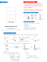
5) Ensure the Power Inserter is in the ON position. If you experience
reception issues, switch the Power Inserter to the OFF position.
This may improve reception in high-signal strength areas.
6) Follow your HDTV’s instruction manual to scan for
channels on your television. Be sure to run a new channel
scan any time you adjust or move the antenna.
WARNING: The Power Inserter and Power Supply are for INDOOR use
only. DO NOT use OUTDOORS.
EASY INSTALLATION FOR ANALOG TVS WITH SET-TOP BOX
1) Connect one end of the Coax Cable to the antenna and the
other end to the Power Inserter.
2) Connect the Power Inserter to your set-top box antenna
input. Then connect another coax cable (not included) to
the antenna output on the set-top box.
3) Connect the other end of that cable to the antenna input
on your TV.
4) Refer to the above section and complete Steps 3 - 6.
Antenna Grounding & Connection (Outdoor installations only)
The National Electric Code (NEC) requires your outdoor antenna
installation to be properly grounded. This involves grounding both the
antenna and the antenna mounting structure. This helps protect you
and your property in the event of static buildup on the antenna or
lightning near your home.
NOTE: If you previously had a satellite or cable system
installed at your home, you may be able to use some of the
parts from this system for your antenna installation.

11
a) Ground the Antenna Mount: When mounting the
antenna to a wall or under an eave using the plastic
antenna mounting bracket provided, this step is not
necessary. In this case, proceed to Step B) Antenna
Connection in this section. This step Ground the
Antenna Mount applies only when mounting the
antenna to a metal mounting structure such as a
metal pole, mast, tower, etc.
Attach a #8 aluminum or a #10 copper grounding wire
to the antenna mounting structure. In some cases, a
bolt on the mount can be used for making this
connection.
Tighten this connection securely. Ensure there is a
good electrical connection between your mounting
structure and grounding wire. Run the grounding wire
as straight as possible and use stand-off insulators
spaced four (4) to six (6) feet apart. Attach the
grounding wire to an acceptable building ground
location.
Examples of acceptable building grounding locations
are:
• The building or structure grounding electrode
system as covered in 250.50 in the NEC
• Grounded interior metal water piping system, within
5ft. from its point of entrance to the building
• Grounded nonflexible metallic power service
raceway
• Service equipment enclosure, the grounding
electrode conductor or the grounding electrode
conductor metal enclosure of the power service
• An 8-foot grounding rod driven into the ground
can be used as long as it is connected to the
central building ground by a #6 or heavier bonding
wire

12
Refer to the NEC sections 250 and 810 for other
acceptable grounding methods.
b) Antenna Connection: Connect one end of a coax
cable to the antenna and the other end to a 75 ohm
grounding block (not provided). Below (Fig. 1a) is an
example of a 75 ohm grounding block.
Fig. 1a
If you make your own coax cable, be sure to slide the
Rubber Boot over the cable before you place the
connectors on the cable. Once you have attached the
cable to the antenna, slide the Rubber Boot into the
round channel on the antenna.
If you are using a pre-built cable that has connectors,
follow these steps.
i. Cut 4 slits spaced evenly apart at the narrow tip of the
provided Rubber Boot approximately ¼” in length.
(Fig. 1b)
Fig. 1b
ii. Run the coax cable through the narrow end of
the Rubber Boot and attach the cable to the
antenna.
iii. Slide the Rubber Boot into the round channel on
the antenna.
iv. Using the Zip Tie, wrap the tie around the
narrow tip of the Rubber Boot, around the four
slits and pull the tie tight.

13
Use a second coax cable and connect one end to the
mating port of the first coax cable on the 75 ohm
grounding block and run the other end into your home
and connect to the Power Inserter. The 75 ohm
grounding block needs to be placed as close as
possible to the point where the second coax cable enters
your home
NOTE: Leave enough slack in the coax cable to create a drip loop
so that moisture cannot enter the house. You will also need to seal
the coax cable entry point into your house with an exterior caulk.
c) Ground the 75 OHM Grounding Block: Connect a #8
aluminum or #10 grounding wire to a screw terminal
provided on the 75 ohm grounding block. Connect the other
end of the wire to an acceptable building ground location.
Refer to Step a) in this section for acceptable building
grounding locations.
Be sure to double check all your connections after your
installation is complete. Ensure there are good electrical
connections of your grounding wires and coax cables.
See Fig. 2 below for an example of a properly grounded
antenna installation.
If you are unsure how to properly ground your antenna
installation, contact a professional installer in your area.

14
d) Danger Label Application: If your metal antenna
mounting structure, such as a mast, J-Mount or pole,
does not have a danger label, apply the danger label
provided to the base of the mounting structure in a
clearly visible location.
ANTENNA REMOVAL
Inspect the area carefully for power lines. Look for any new power
lines that may have been installed. Make sure there is no possibility the
antenna, its mounting structure or your ladder can come in contact
with power lines. Be sure to consider what can go wrong during the
antenna removal. Repeat the steps for antenna installation but in
reverse order.
ANTENNA HELPFUL TIPS
Maximize the number of channels you receive by placing the antenna
in several different locations to see which location provides the best
reception and the maximum number of channels. Be sure to run a
new channel scan on your TV in each position. Refer to the instruction
manual that came with your TV if you are not sure how to do this.
Position or mount the antenna as high as possible facing the
broadcast towers.
Connect the antenna to your TV using the Power Inserter and
Power Supply as described in the Television Connection & Channel
Scanning section. This will ensure that your antenna is receiving power
and is fully functional, if you do not connect the power supply YOUR
ANTENNA WILL NOT WORK. However, depending on your location and
signal environment, the antenna may work best without the power
inserter ON, so switch the power inserter to the OFF position.
NOTE: Even if the Power Inserter is off, it still needs to be plugged
into a power source to provide power to the antenna.
Visit www.antennaweb.org or www.dtv.gov and look for the DTV
Reception Maps to determine the available television stations and
location of the broadcast towers in your area.
FOR FURTHER ASSISTANCE, CALL 1-800-654-8483 Option 1 FOR
TECHNICAL SUPPORT BETWEEN THE HOURS OF 7:30 AM - 5:00 PM
CST.

15
34560 V2
08/22/17
MADE IN CHINA
GE is a trademark of General Electric Company and is
under license by Jasco Products Company LLC, 10 E.
Memorial Rd., Oklahoma City, OK 73114.
This Jasco product comes with a limited-lifetime
warranty. Visit www.byjasco.com for warranty details.
Questions? Contact us at 1-800-654-8483 between
7:00AM—8:00PM CST.

16

Antena amplificada
discreta HD 200
para interiores/
exteriores/áticos
Manual del usuario

18
ADVERTENCIA: INSTALAR ESTE
PRODUCTO CERCA DE CABLES
DE TENSIÓN ES PELIGROSO.
POR SU SEGURIDAD, SIGA
LAS INDICACIONES DE
INSTALACIÓN.
¡PRESTE ATENCIÓN A LOS
CABLES ELÉCTRICOS! EL
CONTACTO DE ESTA ANTENA
CON ALGÚN CABLE ELÉCTRICO
PUEDE CAUSARLE LA MUERTE.
¡LEA LAS INSTRUCCIONES!

19
ÍNDICE
INSTRUCCIONES DE SEGURIDAD IMPORTANTES ................................4
SELECCIONE Y MIDA EL LUGAR DE LA INSTALACIÓN .......................5
ELIJA UN TIPO DE MONTAJE .........................................................................6
INSTRUCCIONES DE ENSAMBLADO: Lista de partes ........................7
INSTRUCCIONES DE ENSAMBLADO:
Cómo ensamblar la antena ..........................................................................8
MONTAJE DE LA ANTENA ...............................................................................9
CONEXIÓN A LA TELEVISIÓN Y BÚSQUEDA DE CANALES ...........10
PUESTA A TIERRA Y CONEXIÓN DE LA ANTENA ................................10
DESINSTALACIÓN DE LA ANTENA ............................................................14
SUGERENCIAS ÚTILES RELACIONADAS CON LA ANTENA ...........14

20
INSTRUCCIONES DE SEGURIDAD IMPORTANTES:
• NUNCA toque NADA ni a NADIE que esté en contacto
con un cable eléctrico. Podría electrocutarse. En caso de
accidente o emergencia, llame al 911 de inmediato para
obtener ayuda.
• INSPECCIONE el sitio de la instalación cuidadosamente
para ver si hay cables eléctricos. Asegúrese de que no
haya ninguna posibilidad de que la antena, la estructura
sobre la que está montada o su escalera puedan tomar
contacto con algún cable eléctrico. Piense en todo
aquello que posiblemente pudiera salir mal durante la
instalación.
• MANTENGA distancia entre los cables eléctricos, la
antena y su estructura de montaje. Tal distancia debe
ser, por lo menos, igual a dos veces la altura combinada
de la antena y la estructura sumadas. En caso de que la
antena se caiga durante la instalación o después, debe
haber distancia suficiente para garantizar que no tome
contacto con un cable eléctrico.
• MANTENGA la escalera, la antena y la estructura de la
antena (como el mástil, el poste, la base de soporte) lejos
de los cables eléctricos en todo momento.
• CONECTE A TIERRA la antena y la estructura de
montaje de la antena de conformidad con el Código
Estadounidense de Normas de Electricidad (NEC) y todos
los requisitos de los códigos eléctricos estatales y locales.
• COMPLETE el ensamblado de la antena en el suelo antes
de montarla.
• NO use una escalera de metal ni instale la antena en un
día ventoso. Si la antena o el mástil comienzan a caerse,
déjelos caer. No intente agarrar la antena.
• TENGA cuidado al trabajar sobre un techo.
• COLOQUE la etiqueta de peligro (que se incluye con la
antena) en la base de la estructura de la antena.
• INFORME a otras personas de los peligros de tocar los
cables eléctricos u otros objetos que puedan estar en
contacto con una línea eléctrica.
/