Page is loading ...

iNSTALLATiON AND SERVICE MUST BE PERFORMED BY
A QUALIRED iNSTALLER.
iMPORTANT: SAVE FOR LOCAL ELECTRICAL INSPECTOR'S USE.
READ AND SAVE THESE INSTRUCTIONS FOR FUTURE REFERENCE.
if the information in this manual is not followed exactly, a fire or explosion may result
causing property damage, personal injury or death.
FOR YOUR SAFETY:
Do not store or use gasoline or other flammable vapors and liquids in the vicinity of this or any other
appliance.
WHAT TO DO iF YOU SMELLGAS:
* Do not try to light any appliance.
* Do not touch any electrlcal switch; do not use any phone in your building.
* immediately call your gas supplier from a neighbor's phone. Follow the gas suppller's instructions.
* if you cannot reach your gas supplier, call the fire department.
installation and service must be performed by a qualified installer, service agency or the gas supplier.
Additional Safeguards
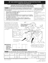
• Do not install wait oven beneath the work counter.
• The oven vent shoutd not be located under 36"
from the floor.
Allow at least 19=3/8" clearance
for complete door opening.
38 /16
A
Electrical Outlet
......Location for model
with 11/2 oven
Drill a 11/2 diameter hole
for gas hook up
Figure 1
A B C D E F G H
10" Min. 24" 20" 22" 371/2'' Min.
271/2'' Max. 11/2'' Min. Min. 7-5/8" 231/2" 38" Max.
NOTE: Wiring diagrams for these appliances are enclosed in this booklet.
Printed in Canada
P,/N 318201556 (1109) Rev. A
English - pages 1-7
EspaBol - p6ginas 8-14
Wiring Diagram - pages 15-16

important Notes to the installer
I. Read all instructions contained in these installation
instructions before installing the appliance.
2. Remove all packing materiai and literature
from the oven and broiler compartments before
connecting gas and electric supply.
3. Observe all governing codes and ordinances.
4. Be sure to leave these instructions with the
consumer.
5. Note: For operation at 2000 ft. elevations above
see level, appliance rating shall be reduced by 4
percent for each additional 1000 ft.
important Nofe to the Consumer
Keep these instructions with your Use and Care
Guide for future reference.
Save these instructions for local inspectors.
iMPORTANT SAFETY
iNSTRUCTiONS
POWER FAILURE
Do not attempt to operate the oven in the event
of a power failure. If power failure should
occur during operation, turn the oven control
to the OFF position. Failure to turn the oven
control off will result in oven operation upon
resumption of power to the unit.
installation of these appliances must conform with
local codes or, in the absence of local codes, with
the National Fuel Gas Code ANSi Z223.1--1atest
edition.
These appliances have been design certified by
American Gas Association (A.G.A.). As with any
appliance using gas and generating heat, there are
certain safety precautions you should follow. You
will find them in the Use and Care Guide., read it
carefully.
• Be sure your wall oven is installed and
grounded properly by a qualified installer or
service technician.
• These wall ovens must be electrlcally grounded
in accordance with local codes or, in their
absence, with the National Electrical Code
ANSI/NFPA No. 70--latest edition. See
grounding instructions farther in this manual.
• The installation of appliances designed for
manufactured (mobile) home installatlon must
conform with Manufactured Home Construction
and Safety Standard Title 24CFR, Part 3280
[Formerly the Federal Standard for Mobile
Home Construction and Safety, Title 24, HUD,
(Part 280)] or when such standard is not
applicable the Standard for Manufactured Home
installation 1982 (Manufactured Home Sites,
Communities and Set=Ups), ANSi Z225.1/NFPA
501=A= latest edition, or with local codes.
Do not store items or food of interest
to children in the cabinets above the appllance.
Children could be seriously burned or injured if
they climb on the appliance to reach these items.
* Do not store or use gasoline or other flammable
vapors and liquids near this or any other
appllance. Explosions or fires could resutt.
* Be certain alt packing materials are removed
from the unit before operating, to prevent fire
or smoke damage should the packing material
ignite.
* Do not leave children alone in the kitchen
when the appliance is in use. They should not
be attowed to sit or stand on any part of the
appliance, as injury or burns coutd resutt. Keep
children from touching the oven door or glass
window when the appliance is operating, as the
door or window could get hot enough to cause
serious burns.
* Remove broiler tray and other utensils from oven
before using the self-clean cycle (if equipped).
* Do not use the oven as a store space. This creates
a potentially hazardous situation.
The appliance requires fresh air for proper burner
combustion. Do not obstruct the flow combustion
air at the oven vent or around the base or
beneath the lower front panel of the appliance.
Avoid touching the event openings or nearby
surfaces, as they may become hot.
* Remember, your oven is not designed to heat your
kitchen. Such abuse could result in fire and/or
damage to the unit and will void your warranty.
1. Carpentry
* Refer to figure 1 for the dimensions applicable
to your appliance, and the space necessary to
receive the oven. Corners must be square.
* Floor cabinet must be able to support 150 pounds
and must be flush with bottom of opening.

2. Connect Electricify Io Gas Wall Oven
For personal safety, these appliances must be
properly grounded.
This appliance is equipped with a
three-prong grounding plug for your protection
against shock hazard and must be plugged directly
into a properly grounded receptacle. Do not cut or
remove grounding prong from this plug.
The walt receptacle and circuit should be checked
by a qualified electrician to make sure the
receptacle is properly grounded.
Where a standard 2-prong walt receptacle is
installed, it is the personal responsibility and
obligation of the consumer to have it replaced by a
property grounded 3-prong wall receptacle.
Preferred Method _o not,under anh
I circumstances, cut, I
remove, or bypass I
Grounding ¢-/4.._!1_ the grounding J
type watt _!_ pr°ng • //
receptacle
Power supply cord with
_ 3-prong grounding plug
Figure 2
Do not, under any circumstances, cut or remove
the third (ground) prong from the power cord.
If an externat electrical source is used, the
appliance, when installed, must be electrically
grounded in accordance with local codes or in their
absence of local codes with the National Electric
Code ANSI/NFPA No. 70-1987 or latest edition.
Check all code rules and regulations for connecting
the walt oven to be certain the installation
conforms with all local, municipal and state codes
as well as local utility regulations.
Failure to comply with the above could result in a
serious shock hazard.
3. Alternate construction
(Model with 11.6oven cavity only)
Installation instructions for installing a 11/2 cavity
oven into an existing 2 cavities opening with
dimensions 42-1/8" height by 22 1/2" Width.
42
Wood
runner
eight
adjuster
Figure 3
* If width opening is too wide to secure unit to
cabinet with mounting screws, add plywood filler
strips.
" If height opening is at 42-1/8", lower height
adjuster 1" (see section 4) and secure two 2" X
4" X 22" wood runners on each side at bottom of
opening (see figure 3).
" The decorative lower trim (not shown) can be
installed to hide the gap under the unit. It should
overlap by 1/4" the front of the cabinet at bottom
of cutout (see step 2 of section 5).
Note: All hook-ups and adjustments shall be
performed by qualified technicians.
Disconnect electrical supply cord
from walt receptacle before servicing walt oven.
3

4. Adjusting Oven Height
(Model with 1 t½ oven cavity only)
Remove and lay aside the lower vent decorative
trim that is taped to the side or to the top of the
oven. The decorative trim will be fastened to the
lower front of the oven after it has been installed in
the cabinet.
There is a 1 1/2" height adjustment on models with
extension panel (see figure 4). With this adjustment
and a 1/2" trim overhang, a unit can be installed in
existing openings 37 1/2" to 39" high.
Oven Door
Oven Bottom
Extension Panel
Adjustment
Holes
Extension
.............Panel Mounting
- .... " .... / Screws
Figure 4
To adjust oven height:
1. Lay oven on its back (see figure 5).
2. Remove the 6 screws that fasten the side
extension panel to the bottom sides of the oven.
3. Move each panel down to the position
that increases the oven height to fit your
opening. Each position changes oven height
approximately 1/2".
4. Line up the appropriate holes in the side
extension panels and sides of the oven. Put the 6
screws back.
5. Proceed with oven installation. Return to upright
position.
Figure 5
5. Cabinet installation
Insert appliance into cutout. Use the 4 mounting
screws provided to fasten the front frame of the
appliance to the cabinet (steps 1 below). Keep the
2 decorative screws to fix the decorative trim to
the cabinet (step 2 below). The mounting holes in
the front frame of appliance may be used as a
template to locate the appliance mounting screw
holes on the cabinet.
To fasten the appilance to the cabinet (figure 6):
1. Use 4 mounting screws supplied to secure the
appliance to the cabinetry. 2 holes are located
under the center vent trim on each side, the
2 other holes are visible when the drawer is
opened.
2. Optionah Instatt the decorative trim under the
appliance (as shown on figure 6) using the 2
decorative screws supplied with the appliance.
Center Vent Trim
Mounting Screws
Mounting Screws
Decorative
Decorative
Figure 6
4

6° Provide an Adequate Gas Supply
Important: Read these instructions carefully before
connecting this unit to a gas supply.
The units covered in these instructions are designed
to operate on natural gas at 4" of manifold
pressure or on LP gas at 10" of manifold pressure.
A convertible pressure regulator is connected
in series with the manifold of the walt oven unit
and must remain in series with the supply line,
regardless of which type of gas is being used.
For proper operation, the maximum inlet pressure
to the regulator must not exceed 14" of water
column (W.C.) pressure.
To check the regulator, the inlet pressure must be
at least 1" (or 3.4 kPa) greater than the regulator
pressure setting. If the regulator is set for 4", the
inlet pressure must be at least 5". If the regulator is
set for 10", the inlet pressure must be at least 11".
A manual shut-off valve must be installed on the
gas supply line external to the unit and where it
can be easily reached for the purpose of turning
the gas to the unit on and off.
The gas supply line to the unit should be 1/2" (1.3
cm) or 3,,&"(1.9 cm) pipe.
To avoid pilot outage (if applicable) close all
openings in the cabinet cavity that encloses this
unit. All openings around gas service outlets must
be closed at the time of installation.
7. Connection to gas (see figure 7)
If flexible gas connector is used, gas llne must be
A.G.A. design certified.
BEFORE CONNECTING THE UNIT
Remove all packing material and literature from
wait oven before connecting gas and electrical
supply to the appliance.
If applicable, remove broiler or storage drawer
by pulling drawer out to stops. Lift drawer front to
clear stops and putt out.
Check for leaks. After connecting gas, check
system for leaks with a manometer, if a manometer
is not available shut all pilots off (if present), turn
on the gas supply to the unit and use a liquid leak
detector at all joints and connections.
Tighten all connections if necessary to prevent gas
leakage in the wait oven or supply line.
IMPORTANT: A pipe joint sealant resistant to
the action of LP Gas must be used on all pipe
connections.
Do not use a flame to check for leaks
from gas connections. Checking for leaks with a
flame may result in a fire or explosion.
Disconnect the oven and its individual shutoff
valve from the gas supply piping system during
any pressure test greater than 1/2psig.
Isolate the wall oven from the gas supply piping
system by closing its individual manual shutoff
valve during any pressure testing of the gas supply
piping system at test pressures equal to or less than
1/2 psig.
8° LP/Propane Gas Conversion
A. Pressure Regulator Conversion
Note: Do not remove the Pressure Regulator.
Connector
External Shut-Off Valve __
Figure 7
Convert the Pressure Regulator for use with LP
Gas (see figure 8)
If applicable, remove broiler or storage drawer
by pulling drawer out to stops. Lift drawer front to
clear stops and putt out.
Locate pressure regulator on lower back walt and
convert as shown in figure 8.
A. Remove the cap from the pressure regulaton
B. Remove the ptungen
C. Turn the plunger upside down with the
enlarged end TOWARDS regulator.
D. Replace the plunger inside the regulator. The
letters LP or 10" W.C. should be visible on the
exposed end of the plunger.
E. Replace the cap on the pressure regulator.
NOTE: The type of gas pressure the regulator is set
for is indicated on the top of the plunger.
5

SMALL End Towards
__ket Regulator For
Natural Gas
ENLARGED End
Towards Regulator _ _
For LP. Gas
Figure 8
B. Adjust Oven Burner Orifice (seeNgure 9)
Pin
Air Shutter
;Oven Burne/r \1
Spud Figure 9
Using a 1/2" wrench, turn down the adjustable spud which
injects gas into the oven burner. Turn spud approximately
21/2 turns until snug against the LP metering pin. Do not
overtighten (see figure 9).
C. Adjust Broller Burner Orifice (Self-Cleaning Models
Only) (see Ngure 10)
Pin
Air
!
Waist-High
Broiler Spud
Figure 10
Using a 1/2" wrench, turn down the adjustable spud which
injects gas into the oven burner. Turn spud approximately
21/2 turns until snug against the LP metering pin. Do not
overtighten (see figure 10).
9. Natural Gas Conversion
Convert the Pressure Regulator for use with
Natural Gas (see figure 8)
A. Remove the cap from the pressure regulator.
B. Remove the plunger.
C. Turn the plunger around so that the small end is
TOWARDS the regulator.
D. Replace the plunger inside the regulator. The
letters NAT or 4" W.C. should be visible on the
exposed end of the plunger.
E. Replace the cap on the pressure regulator.
F. Turn spud approximately 21/2 turns
counterclockwise. This witl move the spud away
from the pin.
G. Apply gas, adjust pilots (if equipped) and
burner air shutter for proper flame.
H. There should be 4" WC pressure in the
manifold after conversion for proper operation
on Natural Gas.
10. Adjustments
Oven/Broiier Flame Adjustment
The air shutter adjustment is located on the venturi
tube, which sets on the spud of the valve, and is
locked in place with a Phillips head screw, if the
air shutter needs adjusting, loosen the screw and
rotate the shutter to allow more or less air to the
burner tube (see figure 11).
Air Adjustment_
Shutter
)_ Loosen
Figure 11
For Natural Gas, the air shutter should be
approximately half open. For LP Gas, the air
shutter nearly full open.
Too much air witl cause the flame to lift away from
the burner. Too little air will cause the flame to turn
yellow at the outer edges and soot to form.
Remember, the oven will be shipped from the
factory set for Natural Gas, unless otherwise
stated. If connecting to LP gas, be sure to follow
procedure under "Conversion" to change the
regulator and burner orifice to the LP setting.
6

Observe the oven burner flame to determine if
it is right. It should be steady with a blue cone
approximately 1" tong and should not extend out
over the edges of baffle. For LP Gas, this will most
likely occur when the air adjustment shutter is
completely open (see figure 12).
Turn Oven Temperature to 300°F and allow oven
burner to cycle on and off.
To replace broiler or storage drawer, reverse steps
taken for removal (see the Use and Care Guide for
complete instructions). Replace oven racks.
Model and Serial Number Location
The serial plate is located on the left side inner trim
of the oven.
When ordering parts for or making inquires about
your wait oven, always be sure to include the model
and serial numbers and a lot number or letter from
the serial plate of your appliance.
Your serial plate also tells you the rating of the
burners, the type of fuel and the pressure the wait
oven was adjusted for when it left the factory.
Stepping, leaning or sitting on the
oven door or drawer can result in serious injuries
and also cause damage to the appliance.
Be sure to keep appliance clear of combustible
materials, gasoline and other flammable vapors
and liquids.
Before You Call for Service
Read the Avoid Service Checklist and operating
and cleaning instructions in your Use and Care
Guide.
Figure 12
11. Check Operation
Refer to the Use and Care Guide packaged with
the walt oven for operating instructions and for
care and cleaning of your appliance.
Do not touch the oven burners. They may be hot
enough to cause burns.
lo
o
Check the Igniters (some models)
Operation of electric igniters should be
checked after oven and supply line connectors
have been carefully checked for leaks and oven
has been connected to electric power.
Oven Igniter System
Close the door and turn the Oven Temperature
to 300°F. In approximately 60 seconds, the
burner should ignite and stay on until oven
reaches 300°F. Burner should then cycle on
and off to maintain an average temperature of
approximately 300°F.
Check to make sure the house fuse or circuit
breaker for your walt oven is not blown or open.
Care, Cleaning and Maintenance for Wall
Ovens
If removing the wall oven is necessary for cleaning
or maintenance, shut off gas supply. Disconnect
the gas and electric supply. Remove the installation
screws from front frame and lower trim. Putt out
only as far as necessary to disconnect the electric
supply line. After disconnecting the gas and
electric supply, finish removing the unit for servicing
and cleaning. Reinstall in reverse order and make
sure that appliance is level; check gas connection
for leaks.
When All Hookups are Complete
Make sure all controls and programmable timer are
left in the OFF position.
Reset all controls to the "OFF" position after using a
programmable timing operation.
7

THIS SIDE OF THE SCHEMATIC.IF YOUR APPLIANCE HAS A LIGHT SWITCH.
ion i
DE ESTE LADO DEL DIAGRAMA ESQUEMATICO.SI SU ELECTRODOMESTICO TIENE L+,
UN INTERRUPTOR DE LUZ. _
OVEN CIRCUIT // CIRCUITO DE HORNO
ELECTRONIC OVEN COI#TROL
CONTROL DE HORNO ELECTRONiCO
ES 3OO
GROUND
PU_STAA
TIERRA
15
w_
TEMPERATUREPROBE_¸
SONDADETE_PE_ATURA
BR
0-I
BAKEVALVE
VALVULADE HORNE_
_AKa_GN_TE_ ;C_
ENCENDIDODEHORNEAR
THERIdlCALCIRCUITBREAKER
RO'CPEDORDE GIRCVITOTERMICO
BROIL VALVE
VALVULA DE ASAR
' 7
SEELEGEND/VERLEYENDA
SWA
LATCH_OTOR/_OTORDECER_OYO
÷?
R-1
iFAN_OTOR
i_OTORDE VENTILADO_ rAN THErmOSTAT
TERMOSTATODE VENTILADOR
' FAN T_E_OSTAT N C
VENTILADOR12_ NO
GAUTION;
LABEL ALL WIRES PRIOR TO DISCONNECTION WHEN SERVICING
CONTROLS,
WIRING ERROR CAN CAUSE [t,_PROPE£ AND DANGEROUS OPERATION.
VERIFY PROPER OPERATION AFTER SERVICING
AVISO:
ETIQU£TE TODOS LOS ALAB_B_ES ANTES DE DESOONECTA_ PA_ _£ALIZAR
ET #A_TENI_IENTO DE LOS CONTROLES,EB£O£ DE ALAMBRAJE PUEDE
CAUBAR UN FUNCIOF,AMIENTO INCOR£ECTO Y PELIGROSO,VERIQUE SI
EL FUNCZONA_IENTO ESTA OORRECTO DESPUES DEL EANTENIMIENTO,
wl
R1
S_,A
LATCH MOTOR
CAUTION: DISCONNECT POWER BEFORE SERVICING UNIT.
AVISO:DESCONECTE LA ENERGIA ANTES DE REALIZAR EL MANTENIMZENTO DEL ELECTRODOMESTICO,
i318046316 REV:B
iPAGE:2/2
THIS SIDE OF THE SCHEMATIC.IF YOUR APPLIANCE HAS A MEMBRANE SWITCH. _,,_
UNA MEMBRANA INTERRUPTOR.
Z
GROUND
PUESTAA
B_OTORLATCH
/,_OTORDE CERROJO
LJ
OPTION,OPCION
OVEN LAMP
LUZ DE HORNO
PYROLITIOUE ONLY
PYROLITZQUE SOl _,_ENT
iR.I
VENTILADOR 120" ij_
CAUTION:
LABELALL W_RESPROR_0 D_SCONNCHON_VHEN8ERV_CING
CONTROLS,
WI_IN_ ERRO_C_ CAUSEI_P_OPERANDDANGEROUSOPERATION.
VERIFYPBOPEROPERATIONAFTERSERVICING,
AVISO:
ETIQU_TETOPOSLOSAL_B_ESANTESDEDESCO_EOTA_PARREAL_ZAR
_T _NIM_ENTO D_ LOSCONTROLES,_RO_D_ AL_RAJ_ PU_D_
CAUSARUN FUNCIONA_IENTOI_CORRECTOY PELIeROSO.VE£IOUES!
_L FU_CIONA_iENTOESTA¢0R_ECT0DESPUESDEL_TENI_NT0,
PYROLiTIQUEONLY
PYROLiTIQUE$OLAMENTE
sv_ A
i"_i i __ .....i
: %-'2/ i
CAUTION: DISCONNECT POWERBEFORE SERVICING UNIT,
AVISO:DESCONECTE LA ENERGIA ANTES DE REALIZAR EL MANTENIMIBNTO DEL ELECTRODOMESTICO,
COLOROODE_CODICOSDE COLOR
G.-GREEN/VERDE
_.-WHZTEIBLANCO
R, REDI_OJO
o,-ORANGE/NARANJA
Y.-YELLOWIA_ARILLO
BR.-_OWldMO_ENO
BL,_LUE/AZUL
B_.-_LACK/N£6_O
i318046316 REV:B
iPAGE:I/2

OVEN CIRCUIT // CIRCUITO DE HORNO
"_ _ CONNECTOR
/ CONNECTOR
R-t
OVEN LAMP SWITCH
INTERRUPTOR LUZ DE HORNO
BAKE IGNITER CONNECTOR
CONNECTOR ENCENDIDO DE HORNEAR
)>
OVEN LAMP
LUZ DE HORNO
R-I W-1
BAKE IGNITER CONNECTOR
CONNECTOR ENCENDIDO DE
HORNEAR W- 1
))
BR-t
R-1
ELECTRONIC OVEN CONTROL
CONTROL DE HORNO ELECTRONICO
SAKE IGNITER
ENCENOIO0 DE
NORNEAR
TEMPERATURE PROBE
SONDA DE TEMPERATURA
V-I f_
w_1
CONNECTOR
CONNECTOR
BAKE VALVE
VALVULA DE HORNEAR
Fx_ q
I\_) I
W_I
\ /
/
W-I
CAUTION:
LABEL ALL WIRES PRIOR TO DISCONNECTION WHEN SERVICING
CONTROLS,
WIRING ERROR CAN CAUSE IMPROPER AND DANGEROUS OPERATION.
VERIFY PROPER OPERATION AFTER SERVICING.
AVISO:
ETIQUETE TODOS LOS ALAMBRES ANTES DE DESCONECTAR PAR REALIZAR
ET MANTENIMIENTO DE LOS CONTROLES,ERROR DE ALAMBRAJE PUEOE
CAUSAR UN FUNCIONAMIENTO INCORRECTO Y PELIGROSO,VERIQUE SI
EL FUNCIONAMIENTO ESTA CORRECTO DESPUES DEL MANTENIMIENTO,
CAUTION: DISCONNECT POWER BEFORE SERVICING UNIT.
AVISO:DESCONECTE LA ENERGIA ANTES DE REALIZAR EL MANTENIMIENTO DEL ELECTRODOMESTICO.
COLOR OODE/COOtGOS DE COLOR
G.-GREEN/VERBE
W.-WHITE/BLANCO
R.-RED/ROJO
O.-ORANGE/NARANJA
Y.-YELLOW/AMARILLO
SR.-BROWN/CAFE
BL.-BLUE/AZUL
BK._BLACK/NEGRO
WIRE GAUGE TEMPiC CSA UL
ALAMBRE MEDIDA
t t8 125 0Lt251 3173
318046317 REV'A
16
/