Hitachi TS1301 User manual

Category
Circular saws
Type
User manual

This manual is also suitable for

UU610
Instruction Manual
Manual de instrucciones
Estación de trabajo universal
UU610
Customer Service 508-677-4130
UU610 UNIVERSAL WORKSTATION
2 INSTRUCTION MANUAL
TracRac Inc. 994 Jefferson Street, Fall River, MA 02721-4893 • 508-677-4130
A
8x
B
5x
C
4x
D
4x
E
4x
F
8x
G
12x
H
4x
I
2x
J
4x
K
4x
M
2x
L
2x
N
2x
2 INSTRUCTION MANUAL
TracRac Inc. 994 Jefferson Street, Fall River, MA 02721-4893 • 508-677-4130
Estimated assembly 30 minutes
Tiempo aproximado de ensamblado: 30 minutos
Tools required
Herramientas necesarias
Customer Service 508-677-4130
Specifications:
Tool weight: 40 lbs.
Beam supports up to 500 lbs.
Supports 20 ft. material
Especificaciones:
Peso ligero de sólo 40 lbs.
La viga soporta hasta 500 lbs.
Soporta material de 20 pies.
UU610 UNIVERSAL WORKSTATION
INSTRUCTION MANUAL 3
TracRac Inc. 994 Jefferson Street, Fall River, MA 02721-4893 • 508-677-4130
O
4x
P
2x
T
2x
U
2x
W
1x
V
1x
X
1x
Q
2x
R
1x
S
1x
Servicio De Cliente 508-677-4130
UU610 UNIVERSAL WORKSTATION
4 INSTRUCTION MANUAL
TracRac Inc. 994 Jefferson Street, Fall River, MA 02721-4893 • 508-677-4130
1
2
N
L
N
M J N L HK
3
H
J
K
UU610 UNIVERSAL WORKSTATION
INSTRUCTION MANUAL 5
TracRac Inc. 994 Jefferson Street, Fall River, MA 02721-4893 • 508-677-4130
4
P
E
G
A
I
AE I G T
U
T
S
B
BU
P
G
UU610 UNIVERSAL WORKSTATION
6 INSTRUCTION MANUAL
TracRac Inc. 994 Jefferson Street, Fall River, MA 02721-4893 • 508-677-4130
5 1/2”
3/4”
5
FA D
O
D
O
F
A
G
G
K
I
B
UU610 UNIVERSAL WORKSTATION
INSTRUCTION MANUAL 7
TracRac Inc. 994 Jefferson Street, Fall River, MA 02721-4893 • 508-677-4130
F
G
B/C
Use appropriate length bolt.
Utilice el perno apropiado de la longitud.
B
F
6
C
B
F G
G
A+F+G
A
UU610 UNIVERSAL WORKSTATION
8 INSTRUCTION MANUAL
TracRac Inc. 994 Jefferson Street, Fall River, MA 02721-4893 • 508-677-4130
7
R W V S
R
W
X
VX
S
UU610 UNIVERSAL WORKSTATION
INSTRUCTION MANUAL 9
TracRac Inc. 994 Jefferson Street, Fall River, MA 02721-4893 • 508-677-4130
PART NO. ITEM HITACHI P/N. DESCRIPTION QTY.
AX-11096-1 726221 BASERAIL 1
AX-14403-5 726222 ALUMINUM LEG 4
01-25517 726223 LEG BRACKET 2
PI-11005 726224 BASERAIL ENDCAP 2
RI-14208 726225 FOOT ENDCAP 4
SP-14201 726226 SPRING LOCK 4
HD-80021 726227 3/8-16 SELF LOCKING HEX NUT 4
HD-80033 726228 3/8-16 x 2.38 BUTTON SOCKET SCREW 4
HD-80034 726229 1/4 x 5/8 RIVET 8
HD-80035 726230 1/8 x 3/8 RIVET 8
HD-80210 H 726231 ST6.3 x 20mm SELF TAPPING SCREW, WASHER HEX HEAD 4
01-25518 726232 WHEEL BRACKET 1
HD-80078 O 726233 3/8 WASHER 2
HD-80150 726234 WHEEL WITH BUSHING 2
HD-80153 M 726235 PUSH CAP 2
HD-80154 N 726236 1/2 WASHER 2
HD-80155 726237 3/8 ROD 1
HD-80204 K 726238 M6-1.0 SELF LOCKING HEX NUT 4
HD-80217 J 726239 SCREW, PAN HEAD M6-1.0 x 16mm 4
ZN-11501 726240 TOOLMOUNT BRACKET 2
ZN-11099 726241 TOOLMOUNT RETAINER 2
ZN-11504 726242 CLAMP HANDLE METRIC 2
AX-11101 726243 KEY 2
AX-11102-2 726206 SUPPORT BEAM 18” 2
01-25512 726244 SAW ADAPTER PLATE 1
PI-11008 O 726245 TOOLMOUNT FOOT 4
SP-14202 726246 CONICAL SPRING 2
HD-80199-1 726247 M8-1.25 x 50mm HEX BOLT 2
HD-80200-1 A 726248 M8-1.25 x 20mm SQUARE HEAD BOLT 6
HD-80200-2 B 726249 M8-1.25 x 40mm SQUARE HEAD BOLT 3
HD-80200-3 C 726250 M8-1.25 x 50mm SQUARE HEAD BOLT 4
HD-80205 F 726251 M8-1.25 SELF LOCKING HEX NUT 11
HD-80206 E 726252 M8-1.25 HEX NUT 2
HD-80211 D 726253 ST8 x 25mm SELF TAPPING SCREW, HEX HEAD 4
HD-80214 G 726254 M8 WASHER 13
BASERAIL and LEGSWHEEL BRACKETTOOL MOUNT
PART NO. ITEM HITACHI P/N. DESCRIPTION QTY.
01-25511 726255 BENT STOP 1
AX-11097-3 726256 SUPPORT ARM 2
AX-11102-1 726257 SUPPORT BEAM 12” 2
AX-11111 U 726258 BUSHING 2
ZN-11504 726259 CLAMP HANDLE METRIC 2
ZN-11108 726260 CLAMP BASE 2
ZN-11500 726261 SUPPORT ADAPTER 2
ZN-11503 726262 WORK SUPPORT BRACKET 2
KB-90021 P 726263 KNOB, 3/8-16 2
KB-90028 T 726264 KNOB, M8-1.25 2
PI-11004 726265 SLIDE PAD 4
PI-11007 726286 ENDCAP 4
HD-11109 726267 SLIDER BOLT PAD 2
HD-12021 726268 3/8-16 RIVNUT 2
HD-80034 726269 1/4 x 5/8 RIVET 8
HD-80078 T 726270 3/8 WASHER 2
HD-80192 726271 1/8 x 5/8 RIVET 2
HD-80200-1 A 726272 M8-1.25 x 20mm SQUARE HEAD BOLT 4
HD-80200-2 B 726273 M8-1.25 x 40mm SQUARE HEAD BOLT 2
HD-80206 E 726274 M8-1.25 HEX NUT 6
HD-80208 726275 M8-1.25 ROUND HEAD BOLT 2
HD-80214 G 726276 M8 WASHER 4
HD-80183 Q 726277 WHEEL, WORK SUPPORT 2
AX-11098-2 726278 STOP PIPE 1
AX-11104 726279 STOP COLLAR 1
AX-11110 726280 SWIVEL STOP 1
HD-80187 W 726281 1/2 WASHER 1
HD-80207 X 726282 M6-1.0 SQUARE NUT 1
HD-80212 V 726283 M6-1.0 X 30MM SOCKET HEADCAP SCREW 1
KB-90020 S 726210 KNOB, 3/8-16 NYLON TIP 1
KB-90022 R 726284 KNOB, 1/2-13 1
EXTENSION STOP SUPPORT ARM
UU610 UNIVERSAL WORKSTATION
TracRac Inc. 994 Jefferson Street, Fall River, MA 02721-4893 • 508-677-4130
10 INSTRUCTION MANUAL
Hitachi
C8FB2, C10FCB, C10FS, C10FSB,
C10FCE, C10FCH, C10FSH, C12LCH,
C12FCH, C12LC, C12LDH, C12FDH.
Bosch
3915, 3912, 4412.
Delta
MS150, 36.075, 36.225, 36-085, 36-225,
36-585, M275, MS250, MS350, 36-255,
36-255L, MS450.
DeWalt
DW703, DW 708, DW705, DW706,
DW706, DW709, DW715, DW716.
Makita
LS1011N, LS1013, LS1212, LS1220,
LS1221.
Milwaukee
6490.
Porter-Cable
3807, 3802.
Rigid
MS1065LZ, MS1250LZ, MS1290LZ.
Ryobi
TS1301, TS1340, TS1350DX,
TS1352DXL, MS1250LS, S1551DXL.
Sears Craftsman
137.212000, 72.24360, 315.21213,
315.212400, 315.212500, 137.212924,
315.212240, 009.23240, 009.29723.
This Universal Workstation is designed to be used with:
INSTRUCTION MANUAL 11
TracRac Inc. 994 Jefferson Street, Fall River, MA 02721-4893 • 508-677-4130
TROUBLE-SHOOTING TIPS.
Issue: Support Arm Assembly has prob-
lems sliding, or handle is too “loose” or too
“tight”.
Solution: Remove any debris from beam
slots. Re-Adjust handle bolt tightness.
(see below).
Issue: “T” Track or “T” slot on Baserail is
damaged.
Solution: File track or slot with flat file to
remove burr/bump.
Issue: Saw is unstable when the
“Toolmount Handles” are put in the unlock
position to remove saw.
Solution: Loosen the Toolmount Beam
fasteners (to the saw or Toolmount) and
re-position the saw, forward or back, on the
Toolmount Bases.
Re-positioning the saw will balance it,
for ease of removal and installation to
the baserail, when the handles are in the
unlock position.
For sliding miter saws, sliding and lock-
ing the saw motor & blade to an alternate
position during removal and installation
should sufficiently stabilize the saw/tool-
mount unit.
Issue: Saw has rubber foot pads on the
saw base that make tool mount installation
difficult.
Solution: Remove rubber foot pads
Issue: Work support is not horizontal or
parallel with the saw table or other support.
Solution: Change angle by placing 5/16’’
washer between the support beam and “T’.
Re-tighten nuts.
To adjust the tension of the bolt, keep handle
in the down position, back nut off, adjust bolt
tension and re-tighten nut.
Hitachi-Koki, USA, Ltd
If necessary on some saws.
Toolmount handle can be positioned
under this cavity.
Saw Base. (Side view)
Foot pads
Washer
Support Beam
“T”
1. Read the Universal Workstation instruction
manual care-fully before assembling the
workstation and mounting the miter saw.
2. This Universal Workstation is designed to be
used with Hitachi (C8FB2, C10FCB, C10FS,
C10FSB, C10FCE, C10FCH, C10FSH, C12LCH,
C12FCH, C12LC, C12FDH, C12LDH), Bosch
(3915, 3912, 4412), Delta (MS150, 36.075,
36.225, 36-085, 36-225, 36-585, M275, MS250,
MS350, 36-255, 36-255L, MS450), DeWalt
(DW703, DW 708, DW705, DW706, DW706,
DW709, DW715, DW716), Makita (LS1011N,
LS1013, LS1212, LS1220, LS1221), Milwaukee
(6490), Porter-Cable (3807, 3802), Rigid
(MS1065LZ, MS1250LZ, MS1290LZ), Ryobi
(TS1301, TS1340, TS1350DX, TS1352DXL,
MS1250LS, S1551DXL),
Sears Craftsman (137.212000, 72.24360,
315.21213, 315.212400, 315.212500, 137.212924,
315.212240, 009.23240, 009.29723), Miter Saws.
Use with additional Miter Saw models has not
yet been verified.
3. The Miter Saw should be firmly mounted to
the Universal Workstation per the instruction
manual.
4. After mounting the Miter Saw to the Universal
Workstation, align, position and balance the
Miter Saw.
5. Before use, verify that all Universal
Workstation parts are free from damage and/
or deformity.
6. Before use, verify that all parts or components
of the Universal Workstation are properly
installed.
7. Before use, swing open each of the legs until
the brass pin clicks, locking the legs in posi-
tion.
8. When mounting the Miter Saw to the
Universal Workstation, make sure that the
tool mount handles are in the “UNLOCK” posi-
tion, so the tool mount will engage with the
main beam. Be sure to hold the saw until it is
secured to prevent it from falling off the main
beam. Handles should then be tightened.
9. Before operating the Miter Saw, confirm that
the tool mount handles on both sides of this
Universal Workstation are firmly tightened
ensuring that the Miter Saw is securely
mounted to the Workstation.
10. When removing the Miter Saw from the
Universal Workstation, loosen the tool mount
handles until they rotate to the “UNLOCK””
position. Hold the Miter Saw firmly to pre-
vent the saw from falling off the main beam.
Carefully remove the Miter Saw.
11. Disconnect the power plug from the power
outlet when mounting or dismounting the
Miter Saw to the Universal Workstation.
12. Do not modify the Universal Workstation in
any manner or use the Universal Workstation
for any purpose other than is stated in these
instructions.
13. Do not sit or stand on the Universal
Workstation. Do not place, hang, or install
anything on the Universal Workstation other
than a Miter Saw.
14. Always use this universal workstation on
a level surface. Do not use it on uneven or
unstable surfaces.
15. Before operating the mounted Miter Saw,
read the Miter Saw instruction manual care-
fully.
16. Because cut material may cause the work-
station to become unbalanced, always be
sure the material is supported properly. Also,
if the piece being cut is placed far beyond
the work support, workstation legs on the
opposite side may suddenly be lifted up due
to weight imbalance. To prevent this from
occurring, hold the opposite side firmly
before cutting.
Customer Service 508-677-4130
IMPORTANT SAFETY INSTRUCTIONS FOR USING THIS UNIVERSAL WORKSTATION
P/N ARTICULO HITACHI P/N. DESCRIPCION CALIDAD
AX-11096-B 726220 RIEL BASE 1
AX-14403-5 726222 PATA DE ALUMINIO 4
01-25517 726223 SOPORTE DE LA PATA 2
PI-11005 726224 TAPA PARA EXTREMOS DEL RIEL BASE 2
RI-14208 726225 INSERTO PARA PIE 4
SP-14201 726226 TRABA DEL RESORTE 4
HD-80021 726227 TUERCA HEXAGONAL CON TRABA AUTOMATICA DE 3/8 - 16 4
HD-80033 726228 TORNILLO DE CAPUCHON de 3/8 - 16 x 2.38 4
HD-80034 726229 REMATE DE 1/8 x 3/8 8
HD-80035 726230 REMATE DE 1/4 x 5/8 8
HD-80210 H 726231 TORNILLO AUTORROSCANTE CON ARANDELA DE CABEZA HEXAGONAL DE ST 6.3 mm x 20 mm 4
01-25518 726232 SOPORTE PARA DISCO 1
HD-80078 L 726233 ARANDELA DE 3/8 2
HD-80150 726234 DISCO CON BUJE 2
HD-80153 M 726235 TAPA A PRESION 2
HD-80154 N 726236 ARANDELA DE 1/2 2
HD-80155 726237 VARILLA DE 3/8 1
HD-80204 K 726238 TUERCA HEXAGONAL CON TRABA AUTOMATICA M6 DE 1.0 4
HD-80217 J 726239 TORNILLO DE CABEZA OVALADA M6 DE 1.0 mm x 16 mm 4
ZN-11501 726240 ABRAZADERA PARA EL MONTAJE DE HERRAMIENTAS 2
ZN-11099 726241 SUJETADOR PARA EL MONTAJE DE HERRAMIENTAS 2
ZN-11504 726242 MANGO DE SUJECION METRICO 2
AX-11101 726243 LLAVE 2
AX-11102-2 726206 VIGA DE SOPORTE DE 18 PULGADAS 2
01-25512 726244 PLACA ADAPTADORA PARA SIERRA 1
PI-11008 O 726245 PIE PARA EL MONTAJE DE HERRAMIENTAS 4
SP-14202 726246 RESORTE CONICO 2
HD-80199-1 726247 PERNOS HEXAGONALES M8 DE 1.25 mm x 50 mm 2
HD-80200-1 A 726248 PERNOS DE CABEZA CUADRADA M8 DE 1.25 mm x 20 mm 6
HD-80200-2 B 726249 PERNOS DE CABEZA CUADRADA M8 DE 1.25 mm x 40 mm 3
HD-80200-3 C 726250 PERNOS DE CABEZA CUADRADA M8 DE 1.25 mm x 50 mm 4
HD-80205 F 726251 TUERCA HEXAGONAL CON TRABA AUTOMATICA M8 DE 1.25 11
HD-80206 E 726252 TUERCA HEXAGONAL M8 DE 1.25 2
HD-80211 D 726253 TORNILLO AUTORROSCANTE CON CABEZA HEXAGONAL ST DE 6.3 mm x 25 mm 4
HD-80214 G 726254 ARANDELA M8 13
RIEL BASE y PATASSOPORTE PARA DISCOMONTAJE DE HERRAMIENTAS
12 INSTRUCTION MANUAL
TracRac Inc. 994 Jefferson Street, Fall River, MA 02721-4893 • 508-677-4130
UU610 UNIVERSAL WORKSTATION
P/N ARTICULO HITACHI P/N. DESCRIPCION CALIDAD
AX-11118 726285 BRAZO DE SOPORTE 2
AX-11102-1 726257 VIGA DE SOPORTE DE 12 PULGADAS 2
ZN-11504 726259 MANGO DE SUJECION METRICO 2
ZN-11108 726260 BASE DE LA PRENSA 2
ZN-11500 726261 ADAPTADOR DE SOPORTE 2
ZN-11503 726262 SOPORTE DE TRABAJO 2
KB-90021 P 726263 PERILLA DE 3/8 - 16 2
PI-11004 726265 BASE GUIA 4
PI-11017 726266 TAPA PARA EXTREMOS 4
HD-11109 726267 BASE GUIA CON PERNO 2
HD-12021 726268 TUERCA REMACHE DE 3/8 -16 2
HD-80034 726269 REMATE DE 1/8 x 3/8 8
HD-80078 L 726270 ARANDELA DE 3/8 2
HD-80192 726271 REMATE DE 1/8 x 5/8 2
HD-80200-1 A 726272 PERNOS DE CABEZA CUADRADA M8 DE 1.25 mm x 20 mm 4
HD-80206 E 726274 TUERCA HEXAGONAL M8 DE 1.25 6
HD-80208 726275 TUERCA HEXAGONAL M8 DE 1.25 2
HD-80214 G 726276 ARANDELA M8 4
AX-11098-2 726278 TUBO DE CIERRE 1
AX-11104 726279 ANILLO DE CIERRE 1
AX-11110 726280 TOPE GIRATORIO 1
HD-80187 W 726281 ARANDELA DE 1/2 1
HD-80207 X 726282 TUERCA CUADRADA M6-1.0 1
HD-80212 V 726283 TORNILLO DE CABEZA DE CAPUCHON M6-1.0 X 30 MM 1
KB-90020 S 726210 PERILLA DE 3/8 –16 CON PUNTA DE NYLON 1
KB-90022 R 726284 PERILLA DE 1/2 -13 1
BRAZO DE SOPORTE
TOPE DE LA EXTENSION
INSTRUCTION MANUAL 13
TracRac Inc. 994 Jefferson Street, Fall River, MA 02721-4893 • 508-677-4130
Esta estación de trabajo universal está diseñada para ser utilizada con sierras ajustables para ángulos:
UU610 UNIVERSAL WORKSTATION
Hitachi
C8FB2, C10FCB, C10FS, C10FSB,
C10FCE, C10FCH, C10FSH, C12LCH,
C12FCH, C12LC, C12LDH, C12FDH.
Bosch
3915, 3912, 4412.
Delta
MS150, 36.075, 36.225, 36-085, 36-225,
36-585, M275, MS250, MS350, 36-255,
36-255L, MS450.
DeWalt
DW703, DW 708, DW705, DW706,
DW706, DW709, DW715, DW716.
Makita
LS1011N, LS1013, LS1212, LS1220,
LS1221.
Milwaukee
6490.
Porter-Cable
3807, 3802.
Rigid
MS1065LZ, MS1250LZ, MS1290LZ.
Ryobi
TS1301, TS1340, TS1350DX,
TS1352DXL, MS1250LS, S1551DXL.
Sears Craftsman
137.212000, 72.24360, 315.21213,
315.212400, 315.212500, 137.212924,
315.212240, 009.23240, 009.29723.
1. Lea completamente el manual de instrucciones
de la estación de trabajo universal antes de
ensamblarla y de montar la sierra ajusta-
ble para ángulos.
2. Esta estación de trabajo universal está diseñada
para ser utilizada con sierras ajustables para
ángulos Hitachi (C8FB2, C10FCB, C10FS, C10FSB,
C10FCE, C10FCH, C10FSH, C12LCH, C12FCH,
C12LC, C12FDH, C12LDH), Bosch (3915, 3912,
4412), Delta (MS150, 36.075, 36.225, 36-085,
36-225, 36-585, M275, MS250, MS350, 36-255, 36-
255L, MS450), DeWalt (DW703, DW 708, DW705,
DW706, DW706, DW709, DW715, DW716),
Makita (LS1011N, LS1013, LS1212, LS1220,
LS1221), Milwaukee (6490), Porter-Cable (3807,
3802), Rigid (MS1065LZ, MS1250LZ, MS1290LZ),
Ryobi (TS1301, TS1340, TS1350DX, TS1352DXL,
MS1250LS, S1551DXL), Sears Craftsman
(137.212000, 72.24360, 315.21213, 315.212400,
315.212500, 137.212924, 315.212240, 009.23240,
009.29723). El uso con otros modelos adicionales
de sierras ajustables para ángulos no se ha pro-
bado todavía.
3. La sierra ajustable para ángulos debe montarse
firmemente en la estación de trabajo universal
según las instrucciones del manual.
4. Una vez que haya montado la sierra ajusta-
ble para ángulos en la estación de trabajo uni-
versal, alinee, ubique y balancee la sierra ajust-
able para ángulos.
5. Antes de usarla, verifique que todas las partes
de la estación de trabajo universal no presenten
deterioros y/o deformidades.
6. Antes de utilizar la estación de trabajo universal,
verifique que todas las piezas y los componentes
estén instalados correctamente.
7. Antes de utilizarla, abra cada una de las patas
hasta que el pasador de latón haga clic y blo-
quee las patas en su posición.
8. Cuando monte la sierra ajustable para ángulos
en la estación de trabajo universal, asegúrese de
que las manijas para montaje de herramientas
estén en la posición “DESBLOQUEADA”, para
que la base para montaje de la herramienta
calce en la viga principal. Asegúrese de sos-
tener la sierra hasta que esté asegurada para
evitar que se caiga de la viga principal. Luego,
debe ajustar las manijas.
9. Antes de poner en funcionamiento la sierra
ajustable para ángulos, compruebe que las
manijas para montaje de herramientas estén
firmemente ajustadas, para asegurarse de que
la sierra ajustable para ángulos esté montada de
manera segura en la estación de trabajo univer-
sal.
10. Cuando extraiga la sierra ajustable para ángulos
de la estación de trabajo universal, gire las mani-
jas de montaje hasta que queden en la posición
“DESBLOQUEADA”. Sostenga firmemente la
sierra ajustable para ángulos a fin de evitar que
se caiga de la viga principal. Extraiga cuidadosa-
mente la sierra ajustable para ángulos.
11. Cuando monte o la sierra ajustable para ángulos
en la estación de trabajo universal o cuando la
desmonte, desconecte el enchufe del tomacor-
riente.
12. No modifique de ninguna manera la estación de
trabajo universal ni la utilice para otros propósi-
tos que no sean los que están especificados por
estas instrucciones.
13. No se siente ni se pare en la estación de trabajo
universal. No coloque, no cuelgue ni instale en
la estación de trabajo universal otra cosa que no
sea la sierra ajustable para ángulos.
14. Utilice siempre esta estación de trabajo univer-
sal en una superficie nivelada. No la utilice en
superficies desparejas o inestables.
15. Antes de poner en funcionamiento la sierra
ajustable para ángulos una vez que esté monta-
da, lea atentamente el manual de instrucciones
de la sierra.
16. Dado que el material que se va a cortar puede
hacer que la estación de trabajo pierda el bal-
ance, asegúrese siempre de que el material esté
sujetado correctamente. Además, si la pieza
que se va a cortar está ubicada más allá del
soporte de trabajo, las patas del lado opuesto
pueden levantarse súbitamente a causa del mal
balanceo del peso. Para evitar que esto ocurra,
sostenga firmemente el lado opuesto antes de
realizar el corte.
Servicio De Cliente 508-677-4130
14 INSTRUCTION MANUAL
TracRac Inc. 994 Jefferson Street, Fall River, MA 02721-4893 • 508-677-4130
CONSEJOS PARA LA SOLUCION DE
PROBLEMAS
Problema: El ensamblado del brazo de soporte
tiene problemas con el deslizamiento, o la manija
está demasiado “floja” o demasiado “ajustada”.
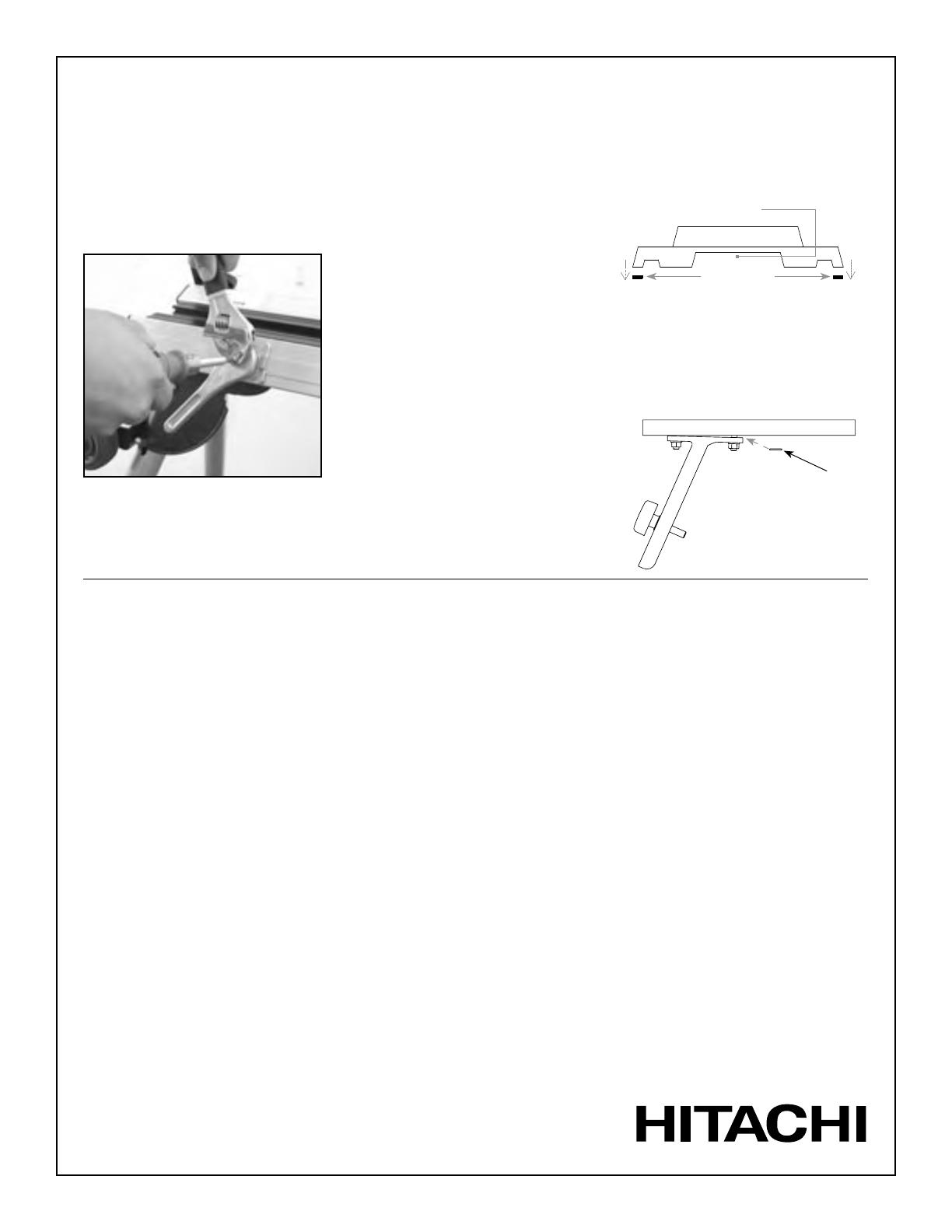
Solución: Quite los desechos de las ranuras de
las vigas. Reajuste la tensión del perno de la
manija. (Vea la ilustración de abajo).
Problema: El carril o la ranura en forma de “T”
del riel base están dañados.
Solución: Lime el carril o la ranura con una lima
plana para quitar las rebabas o las abolladuras.
Problema: La sierra queda inestable cuando se
aflojan las “manijas para montaje de herramien-
tas” para extraer la sierra.
Solución: Afloje los sujetadores para montaje
de herramientas de la viga (de la sierra o de las
bases para montaje de herramientas) y vuelva a
ubicar la sierra, hacia delante o hacia atrás, en
las bases para montaje de herramientas.
• La reubicación de la sierra la balanceará, para
facilitar la extracción y la instalación en el riel
base, cuando las manijas estén en la posición
desbloqueada.
• En el caso de las sierras ajustables para ángu-
los, el deslizamiento y el bloqueo del motor y
la hoja de la sierra en una posición alternativa
deberían ser suficientes para estabilizar la sierra
o la unidad para montaje de herramientas.
Problema: Las almohadillas de hule que la sierra
tiene en las patas de la base dificultan la insta-
lación.
Solución: Quite las almohadillas de hule de las
patas
Problema: El soporte de trabajo no está hori-
zontal o paralelo a la mesa de la sierra o a otros
soportes.
Solución: Cambie el ángulo, colocando una aran-
dela de 5/16” entre la viga de soporte y la “T”.
Vuelva a ajustar las tuercas.
Para ajustar la tensión del perno, mantenga
la manija en la posición inferior, desajuste la
tuerca, ajuste la tensión del perno y vuelva a
ajustar la tuerca.
Hitachi-Koki, USA, Ltd
Si es necesario, en algunas sierras, el mango
del soporte para herramientas puede ser
colocado debajo de esta cavidad.
Base de la sierra. (Vista lateral)
Tapones para pie
Arandela
Viga de soporte
“T”
INSTRUCCIONES IMPORTANTES DE SEGURIDAD PARA UTILIZAR ESTA ESTACION DE TRABAJO UNIVERSAL
UU610_IM-A02
  • Page 1 1
  • Page 2 2
  • Page 3 3
  • Page 4 4
  • Page 5 5
  • Page 6 6
  • Page 7 7
  • Page 8 8
  • Page 9 9
  • Page 10 10
  • Page 11 11
  • Page 12 12
  • Page 13 13
  • Page 14 14

Hitachi TS1301 User manual

Category
Circular saws
Type
User manual
This manual is also suitable for

Ask a question and I''ll find the answer in the document

Finding information in a document is now easier with AI

in other languages