Page is loading ...

SLx2B Aerial amplifier instruction manual
INTRODUCTION
The SLxB series amplifiers are designed to improve the picture and sound quality of TV and FM
radio signals and distribute these to multiple locations around your home. The SLx2B can also be
used to distribute a VCR, Digital Television and Sky™/ Sky+™ signal to two televisions around
the home.
All SLxB amplifiers have an integrated by-pass designed to allow the user control digital Sky™
and Sky+™ receivers from any of the connected televisions using an infrared link device and a
Sky™ or Sky+™ compatible remote control.
For added safety the SLx2B has built-in short circuit protection on each individual output.
Should a short circuit be detected, the amplifier will only shut down the output with the short
circuit; the other outputs will continue to function as normal.
The amplifiers are easy to install and fully automatic in operation, meaning that no user
adjustment is required. The low running cost permits continuous operation.
With full instructions and wall mounting template, installing the SLx2B aerial amplifier is both
quick and easy.
INSTALLING THE SLx2B AMPLIFIER
The SLx2B amplifier can be installed in either a room location or in a loft. Choose your installation
position according to your personal preference. Please be aware that long runs of cable can
become subject to interference so avoid unnecessary long lengths of cable.
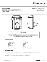
METHOD 1
TV SIGNAL DISTRIBUTION
CONNECTION DIAGRAM
1. Connect your UHF aerial downlead to the IN UHF socket on the SLx2B.
2. Connect your TVs to any of the SLx2B TV sockets in any combination.
METHOD 2
TV/VCR DISTRIBUTION
CONNECTION DIAGRAM
1. Connect your UHF aerial downlead (typically via an aerial wall socket) to the aerial input on
your VCR.
2. Connect an aerial fly-lead from the aerial output on your VCR to the IN UHF socket on the
SLx2B.
3. Connect your TVs to any of the SLx2B TV sockets in any combination.
Once connected, you can tune each television to traditional terrestrial channels and a channel for
VCR viewing.
If you want to connect independent VCRs in each location, connect using METHOD 1 but
connect the SLx2B TV output/s to your VCR/s, then connect your VCR/s to your television/s.
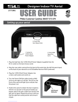
METHOD 3
TV/VCR/SATELLITE DISTRIBUTION
CONNECTION DIAGRAM

This connection method will allow for infrared link devices to be installed one or more of the TV
locations. These devices allow you to control your Sky™ or Sky+™ receiver from any TV location
not having a clear line of sight of the receiver.
1. Connect your UHF aerial downlead to the aerial input on the VCR.
2. Connect an aerial fly-lead from the aerial output on the VCR to the aerial input on the satellite
receiver.
3. Connect an aerial fly-lead from the RF2 output on the satellite receiver to the IN UHF socket on
the SLx2B.
4. Connect your TVs to any of the SLx2B TV sockets in any combination.
Once connected, you can tune each television to traditional terrestrial channels, a channel for
VCR viewing and a channel for satellite viewing.
Note. Only one satellite channel can be viewed at any one time without the use of additional
satellite receivers and subscriptions.
Note. It may be necessary to retune your VCR when used with a satellite receiver. Please consult
your VCR owners manual for details.
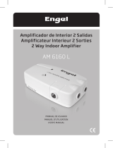
METHOD 4
TV/VCR/DTT (DIGITAL TERRESTRIAL TELEVISION) DISTRIBUTION
CONNECTION DIAGRAM
1. Connect your UHF aerial downlead to the aerial input on the DTT.
2. Connect an aerial fly-lead from the aerial output on your DTT receiver to the aerial input on
your VCR.
3. Connect an aerial fly-lead from the aerial output on your VCR to the IN UHF socket on the
SLx2B.
4. Connect your TVs to any of the SLx2B TV sockets in any combination.
Once connected, you can tune each television to traditional terrestrial channels, a channel for
VCR viewing and a channel for DTT viewing.
If you are receiving poor DTT reception then connect the SLx2B amplifier before your DTT
receiver to boost the signal strength. In most cases, poor DTT reception can only be cured by
acquiring a suitable aerial (see troubleshooting) or waiting until DTT coverage improves in your
area.
Note. Only one DTT channel can be viewed at any one time without the use of additional DTT
receivers.
TROUBLESHOOTING
If you are still experiencing reception problems after installing the SLx2B amplifier, please
refer to the below troubleshooting guide:
No picture or sound
No signal is reaching your television due to a possible break in the aerial signal path. Ensure that
all equipment has been switched on (including the SLx2B amplifier) and that all coaxial
connectors have been fitted correctly.
Snowy picture
Your signal strength is too weak. You may have to use a masthead aerial amplifier improve the
signal quality from the UHF aerial downlead. Also ensure that your aerial is positioned correctly
(pointing at your local TV transmitter). For details of your local television transmitters, visit
www.bbc.co.uk/reception. Aging aerials become corroded by the weather, which may need to be

replaced. Also check that the position of the aerial has not been misaligned by weather, birds, or
loft activity.
'Herringbone' pattern
'Herringboning' is generally caused by too strong signal or possibly by local high power
transmitters such as CB, amateur or taxi radios. Your TV sound may be affected as well as the
picture. Use a signal attenuator (available from your local electrical retailer) to reduce the gain of
your aerial signal and improve your picture. If you are located very close to your local television
transmitter, point your aerial at an alternative transmitter in order to receive a more suitable level
signal.
Problems with DTT
Unlike analogue terrestrial television, it is not possible to view DTT channel under weak signal
strength conditions. Therefore, typically you will either receive DTT channels with a clear picture
and sound or you will not receive any channels at all.
Sometimes, an insufficient digital signal can cause occasional blocking, freezing or complete loss
of picture. Some roof aerials may not be suitable for digital terrestrial television. Ensure that you
have fitted a suitable wideband, high gain aerial to help improve signal quality to a suitable level
for clear DTT reception
Blocking, freezing or complete loss of picture can also occur when a digital signal is too strong, If
your signal is too strong then connect your DTT receiver directly to the UHF aerial downlead,
then connect the SLx2B amplifier to your DTT receiver output followed by your remaining
equipment. If the signal is still too strong, fit a signal attenuator between the aerial downlead and
DTT receiver to help reduce the signal strength.
For specific help with digital terrestrial television reception problems, visit www.dtg.org.uk
Problems with satellite television
If you are experiencing any problems with your satellite television picture, check that all cables
and connectors have been fitted correctly. If the problem persists it is probably due to the dish
alignment or a temporary problem with the channel transmissions. Please contact your local
satellite dealer if the problem persists.
Technical Support
If you are experiencing problems setting up your SLx2B amplifier, or have any questions
regarding this product or any other product within the Philex range, please call the Philex
Customer Care Line on 08457 573 479 (UK only). Calls are charged at local rate. Mobile call
charges may vary, please contact your network provider for details.
Alternatively, please visit our technical website at http://technical.philex.com
TECHNICAL SPECIFICATIONS
Inputs 1
Outputs 2
Frequency range UHF 470 - 862MHz
VHF 47 - 230MHz
Max output level 94dBµV
Gain 6dB per split
Noise 3.5dB
Isolation loss 22dB
Weight 330g
Dims (w x d x h) 130 x 75 x 45mm
/