Crown XLS 202 Operating instructions

Category
Supplementary music equipment
Type
Operating instructions

This manual is also suitable for

Crown XLS 202 is a reliable and affordable power amplifier that delivers 350 watts of power per channel into 8 ohms, ideal for powering speakers in a variety of applications. With its simple design, it offers XLR inputs, touch-proof binding post outputs, and features like anti-clip limiters, high-pass filters, and protection systems for safe and efficient operation.

Crown XLS 202 is a reliable and affordable power amplifier that delivers 350 watts of power per channel into 8 ohms, ideal for powering speakers in a variety of applications. With its simple design, it offers XLR inputs, touch-proof binding post outputs, and features like anti-clip limiters, high-pass filters, and protection systems for safe and efficient operation.

XLS Series
Operation Manual
©2001 by Crown International P.O. Box 1000, Elkhart, Indiana 46515-1000 U.S.A. Telephone: 574-294-8000
Some models may be exported under the name Amcron.®
Trademark Notice: Crown
®
and Amcron
®
are registered trademarks of Crown Audio, Inc. Other trademarks are the property of their
respective owners.
Obtaining Other Language Versions: To obtain information in another language about the use of this product, please contact your
local Crown Distributor. If you need assistance locating your local distributor, please contact Crown at 574-294-8000.
This manual does not include all of the details of design, production, or variations of the equipment. Nor does it cover every possible
situation which may arise during installation, operation or maintenance.
The information provided in this manual was deemed accurate as of the publication date. However, updates to this information may
have occurred.
133465-3
11/01
XLS 202
XLS 402
XLS 602
XLS Series Power Amplifi ers
Operation Manual
page 2
1) Read these instructions.
2) Keep these instructions.
3) Heed all warnings.
4) Follow all instructions.
5) Do not use this apparatus near water.
6) Clean only with a dry cloth.
7) Do not block any ventilation openings.
Install in accordance with the manufactur-
er’s instructions.
8) Do not install near any heat sources such
as radiators, heat registers, stoves, or
other apparatus that produce heat.
9) Do not defeat the safety purpose of
the polarized or grounding-type plug. A
polarized plug has two blades with one
wider than the other. A grounding-type
plug has two blades and a third ground-
ing prong. The wide blade or the third
prong is provided for your safety. If the
provided plug does not fi t into your
outlet, consult an electrician for replace-
ment of the obsolete outlet.
10) Protect the power cord from being walked
on or pinched, particularly at plugs, con-
venience receptacles, and the point where
they exit from the apparatus.
11) Only use attachments/accessories speci-
ed by the manufacturer.
Important Safety
Instructions
MAGNETIC FIELD
CAUTION! Do not locate sensitive high-gain
equipment such as preamplifi ers or tape decks
directly above or below the unit. Because this
amplifi er has a high power density, it has a
strong magnetic fi eld which can induce hum into
unshielded devices that are located nearby. The
eld is strongest just above and below the unit.
If an equipment rack is used, we recommend
locating the amplifi er(s) in the bottom of the rack
and the preamplifi er or other sensitive equipment
at the top.
The lightning bolt triangle is used to alert the user
to the risk of electric shock.
The exclamation point triangle is used to alert
the user to important operating or maintenance
instructions.
WATCH FOR THESE SYMBOLS:
IMPORTANT
The XLS Series amplifi ers require Class 2 output
wiring.
TO PREVENT ELECTRIC SHOCK DO NOT REMOVE
TOP OR BOTTOM COVERS. NO USER SER-
VICEABLE PARTS INSIDE. REFER SERVICING TO
QUALIFIED SERVICE PERSONNEL.
12) Use only with a cart, stand, bracket, or
table specifi ed by the manufacturer, or
sold with the apparatus. When a cart is
used, use caution when moving the cart/
apparatus combination to avoid injury
from tip-over.
13) Unplug this apparatus during lightning
storms or when unused for long periods
of time.
14) Refer all servicing to qualifi ed service
personnel. Servicing is required when
the apparatus has been damaged in any
way, such as power-supply cord or plug
is damaged, liquid has been spilled or
objects have fallen into the apparatus, the
apparatus has been exposed to rain or
moisture, does not operate normally, or
has been dropped.
15) To reduce the risk of fi re or electric shock,
do not expose this apparatus to rain or
moisture.
À PRÉVENIR LE CHOC ÉLECTRIQUE N ENLEVEZ
PAS LES COUVERCLES. IL N’Y A PAS DES PAR-
TIES SERVICEABLE À L’INTÉRIEUR. TOUS REP-
ARATIONS DOIT ETRE FAIRE PAR PERSONNEL
QUALIFIÉ SEULMENT.
XLS Series Power Amplifi ers
Operation Manual
page 3
Table of Contents
Important Safety Instructions ...................................................... 2
1 Welcome ...................................................................................... 4
1.1 Features......................................................................... 4
1.2 Unpacking Your Amplifi er .......................................... 4
2 How to Use This Manual........................................................... 4
3 Setup............................................................................................. 5
3.1 Unpack Your Amplifi er................................................ 5
3.2 Voltage Selection ........................................................ 5
3.3 Mount Your Amplifi er.................................................. 5
3.4 Ensure Proper Cooling................................................ 5
3.5 Choose Input Wire and Connectors ......................... 6
3.6 Choose Output Wire and Connectors....................... 6
3.7 Wire Your System........................................................ 7
3.7.1 Stereo Mode...................................................... 7
3.7.2 Bridge-Mono Mode .......................................... 7
3.8 Connect to AC Mains................................................... 8
3.9 Startup Procedure........................................................ 8
4 Operation ..................................................................................... 8
4.1 Precautions.................................................................... 8
4.2 Front Panel Controls and Indicators........................ 9
4.3 Back Panel Controls and Connectors .................... 10
5 Advanced Features and Options............................................ 11
5.1 Protection Systems ................................................... 11
5.1.1 Anti-Clip Limiters........................................... 11
5.1.2 High-Pass Filters............................................ 11
5.1.3 Output Current Limiting ................................ 11
5.1.4 DC Protection .................................................. 11
5.1.5 Fuse .................................................................. 11
5.1.6 Thermal Protection ........................................ 11
6 Troubleshooting........................................................................ 12
7 Specifi cations............................................................................ 13
8 Service........................................................................................ 15
8.1 Worldwide Service.................................................... 15
8.2 US and Canada Service............................................ 15
8.2.1 Factory Service .............................................. 15
9 Warranty..................................................................................... 16
Factory Service Information Form ............................................ 19
XLS Series Power Amplifi ers
Operation Manual
page 4
The XLS Series of power amplifi ers from
Crown represents a new era in affordable,
quality power amplifi cation. The line consists
of three models in a uniform, rugged
chassis, incorporating the best of tried-and-
true design principles and innovative features.
Modern power amplifi ers are sophisticated
pieces of engineering capable of producing
extremely high power levels. They must be
treated with respect and correctly installed if
they are to provide the many years of reliable
service for which they were designed.
In addition, XLS Series amplifi ers include a
number of features which require some expla-
nation before they can be used to their maxi-
mum advantage.
Please take the time to study this manual so
that you can obtain the best possible service
from your amplifi er.
1.1 Features
Simple, reliable design incorporates many
popular features.
Selectable high-pass fi lter on each channel
enables amplifi er to work more effi ciently
when full band-width is not required (eg:
two- or three-way systems).
1 Welcome
2 How to Use This
Manual
This manual provides you with the necessary
information to safely and correctly setup and
operate your amplifi er. It does not cover
every aspect of installation, setup or operation
that might occur under every condition. For
additional information, please consult Crown’s
Amplifi er Application Guide (available online at
www.crownaudio.com), Crown Tech Support,
your system installer or retailer.
We strongly recommend you read all instruc-
tions, warnings and cautions contained in this
manual. Also, for your protection, please send
in your warranty registration card today. And
save your bill of sale—it’s your offi cial proof
of purchase.
Pair of linear optocoupler clip limiters pro-
tects loudspeakers from being overdriven.
Housed in a rugged, all-steel 3U chassis.
Effi cient forced-air fan prevents excessive
thermal buildup.
Electronically balanced XLR inputs and
touch-proof binding post outputs.
Features precision detented level controls,
power switch, and four LEDs, which indi-
cate clip for each channel, power and fault
conditions.
1.2 Unpacking Your Amplifi er
Please unpack and inspect your amplifi er for
any damage that may have occurred during
transit. If damage is found, notify the trans-
portation company immediately. Only you can
initiate a claim for shipping damage. Crown
will be happy to help as needed. Save the
shipping carton as evidence of damage for the
shipper’s inspection.
We also recommend that you save all packing
materials so you will have them if you ever
need to transport the unit. Never ship the
unit without the factory pack.
XLS Series Power Amplifi ers
Operation Manual
page 5
3 Setup
Figure 3.3 Airfl ow
Figure 3.2 Dimensions
3.4 Ensure Proper Cooling
When using an equipment rack, mount units
directly on top of each other. Close any open
spaces in rack with blank panels. DO NOT
block side or front air vents.
Figure 3.3 illustrates standard amplifier air-
flow.
3.1 Unpack Your Amplifi er
YOU WILL NEED (not supplied):
Two input wiring cables
Two output wiring cables
Rack for mounting amplifi er (or a stable
surface for stacking)
WARNING: Before you start to set up
your amplifi er, make sure you read and
observe the Important Safety Instruc-
tions found at the beginning of this
manual.
3.2 Voltage Selection
CAUTION: Before use, your amplifi er
must be set to the correct operating
voltage for your local supply. Typically,
units are shipped from the factory with voltage
already set with the correct setting, but this
setting should be verifi ed before fi rst using the
amplifi er.
The selected voltage is displayed on the top,
left side of the fuse drawer (see Figure 3.1). To
change the voltage setting; disconnect the power
source, then gently pry out the fuse casing from
the fuse drawer. Replace with the correct voltage
positioned to display on the top left side.
Be sure to operate your amplifi er from a power
supply within ±10% of the rated voltage (i.e.,
108-132V for 120V supply).
Figure 3.1
Voltage Selection
2 in.
3.3 Mount Your Amplifi er
CAUTION: Before you begin, make sure
your amplifi er is disconnected from the
power source, with power switch in the
“off” position and all level controls
turned completely down (counterclock-
wise).
Use a standard 19-inch (48.3 cm) equipment
rack. See Figure 3.2 for amplifi er dimensions.
You may also stack amps without using a
cabinet.
NOTE: When transporting, amplifi ers should be
supported at both front and back.
XLS Series Power Amplifi ers
Operation Manual
page 6
Figure 3.4. Input Connector Wiring
3 Setup
3.5 Choose Input Wire
and Connectors
Crown recommends using pre-built or profes-
sionally wired, balanced line (two-conductor
plus shield), 22-24 gauge cables and connec-
tors. You should use 3-pin male XLR cable
ends at the amplifi er inputs. Unbalanced line
may also be used but may result in noise over
long cable runs.
Note: Male XLR signal links are also provided
on the amplifi er to allow daisy-chaining of the
audio signal.
Refer to Figure 3.4 for correct XLR connector
pin assignments.
NOTE: Custom wiring should only be
performed by qualifi ed personnel.
Figure 3.5. Output Connector Wiring
3.6 Choose Output Wire
and Connectors
Crown recommends using pre-built or pro-
fessionally wired, high-quality, two- or four-
conductor, heavy gauge speaker wire and
connectors. You may use banana plugs, spade
lugs or bare wire for your output connectors
(see Figure 3.5). To prevent the possibility
of short-circuits, wrap or otherwise insulate
exposed loudspeaker cable connectors.
Using the guidelines below, select the appro-
priate size of wire based on the distance from
amplifi er to speaker.
Distance Wire Size
up to 25 ft. 16 gauge
26-40 ft. 14 gauge
41-60 ft. 12 gauge
61-100 ft. 10 gauge
101-150 ft. 8 gauge
151-250 ft. 6 gauge
CAUTION: Never use shielded cable for
output wiring.
XLS Series Power Amplifi ers
Operation Manual
page 7
3 Setup
3.7 Wire Your System
3.7.1 Stereo Mode
Typical input and output wiring is shown in
Figure 3.6.
INPUTS: Connect input wiring for both
channels.
OUTPUTS: Maintain proper polarity (+/-) on
output connectors.
Connect Channel 1 positive (+) speaker load
to Channel 1 positive (red) terminal of amp;
repeat for negative (-). Repeat Channel 2 wiring
as for Channel 1.
3.7.2 Bridge-Mono Mode
Typical input and output wiring is shown in
Figure 3.7.
INPUTS: Use a custom “Y” adapter cable,
wired to split the signal and invert the polarity
for the Channel 2 amplifi er input as shown in
Figure 3.8. We recommend you label the ends
of the Y adapter to help make sure to connect
the correct end to each amplifi er input.
Connect the Y adapter between the signal
source and each amplifi er input.
NOTE: Crown provides a reference of wiring
pin assignments for commonly used connector
types in the Crown Amplifi er Application Guide
(Section 1.21.) available at www.crownaudio.
OUTPUTS: Connect the speaker across the red
binding post of each channel. Do not use the
black binding posts when the amp is being
operated in Bridge-Mono mode.
NOTE: The Channel 1 and 2 level con-
trols MUST be set to identical settings
when operating the XLS amplifi er in
Bridge-Mono mode.
1 0
11 V
1 0V
11 V
Figure 3.6. System Wiring, Stereo Mode
Figure 3.7. System Wiring, Bridge-Mono Mode
Figure 3.8. Custom Input Cable for Bridge-Mono Mode
XLS Series Power Amplifi ers
Operation Manual
page 8
4 Operation
4.1 Precautions
Your XLS Series amplifi er is protected from
internal and external faults, but you should
still take the following precautions for optimum
performance and safety:
1. Before use, your amplifi er fi rst must be
confi gured for proper operation, includ-
ing input and output wiring hookup.
Improper wiring can result in serious
operating diffi culties. For information
on wiring and confi guration, please
consult the Setup section of this
manual or, for advanced setup tech-
niques, consult Crown’s Amplifi er
Application Guide available online at
www.crownaudio.com.
2. Use care when making connections,
selecting signal sources and controlling
the output level. The load you save may
be your own!
3. Do not short the ground lead of an
output cable to the input signal ground.
This may form a ground loop and cause
oscillations.
4. Never connect the output to a
power supply, battery or power
main. Electrical shock may result.
5. Tampering with the circuitry, or making
unauthorized circuit changes, may be
hazardous and invalidates all agency
listings.
6. Never operate the amplifi er with the
red Clip LEDs constantly fl ashing.
7. Do Not overdrive the mixer, which will
cause a clipped signal to be sent to
the amplifi er. Such signals will be repro-
duced with extreme accuracy, and loud-
speaker damage may result.
8. Never operate the amplifi er with less
than the rated load impedance. Due to
the amplifi er’s output protection, such
a confi guration may result in premature
clipping and speaker damage.
9. XLS Series amplifi ers feature a built-in
Anti-Clip Limiter which, when selected,
will provide a high degree of protection
against amplifi er clipping. Crown rec-
ommends activating the limiter whenever
sensible operation of the system cannot
be ensured.
Remember: Crown is not liable for
damage that results from overdriving
other system components.
3.8 Connect to AC Mains
Connect your amplifi er to the AC mains power
source (power outlet) with the supplied AC
power cordset. First, connect the IEC end of the
cordset to the IEC connector on the amplifi er;
then, plug the other end of the cordset to the
AC mains.
NOTE: The third prong of this connector
(ground) is an important safety feature. Do not
attempt to disable this ground connection by
using an adapter or other methods.
Amplifi ers don’t create energy. The AC mains
voltage and current must be suffi cient to deliver
the power you expect. You must operate your
amplifi er from an AC mains power source with
not more than 10% variation above or below
the amplifi er’s specifi ed line voltage and within
the specfi ed frequency requirements (indicated
on the amplifi er’s back panel label). If you are
unsure of the output voltage of your AC mains,
please consult your electrician.
3.9 Startup Procedure
Use the following procedure when fi rst turning
on your amplifi er:
1. Turn down the level of your audio source.
2. Turn down the level controls of the ampli-
er.
3. Turn on the “Power” switch. The Power
indicator should glow.
4. Turn up the level of your audio source to
an optimum level.
5. Turn up the Level controls on the ampli-
er until the desired loudness or power
level is achieved.
6. Turn down the level of your audio source
to its normal range.
If you ever need to make any wiring or instal-
lation changes, don’t forget to turn off the
amplifi er and disconnect the power cord.
For help with determining your system’s
optimum gain structure (signal levels)
please refer to the Crown Amplifi er
Application Guide, available online at
www.crownaudio.com.
3 Setup
XLS Series Power Amplifi ers
Operation Manual
page 9
4 Operation
4.2 Front Panel Controls
and Indicators
A. Cooling Vents
Front-to-rear forced airfl ow.
B. Level Controls
Two black rotary level controls, one for
each channel.
C. Clip Indicators
Two red LEDs, one for each channel, illu-
minate when the channel’s output signal is
being overdriven.
D. Power Indicator
Green LED indicates amplifi er has been
turned on and AC power is available.
E. Fault Indicator
Yellow LED illuminates when amplifi er is
in protect mode. Also illuminates briefl y
during normal power-up when amplifi er is
rst switched on.
F. Power Switch
Amplifi er is on when the switch is in the
UP position.
Figure 4.1 Front Panel Controls
and Indicators
XLS Series Power Amplifi ers
Operation Manual
page 10
4 Operation
4.3 Back Panel Controls
and Connectors
G. Power Connector
H. Fuse
Provides overload protection.
I. Voltage Selector
Two-position switch is factory-set to coun-
try-specifi c voltage. WARNING: Do not
operate your amplifi er with an incor-
rect voltage selected or amplifi er
damage may result.
J. Male XLR Signal Links
One per channel; male XLR connectors
are provided for daisy-chaining to other
amplifi ers.
K. Balanced XLR Inputs
One per channel; three-pin female XLR
input connectors are provided.
L. Filter Switches
One per channel; three-position switch sets
the internal high-pass fi lter frequency. Fre-
quency setting is 30 Hz when switch is
in left position; 15 Hz when switch is cen-
tered; and bypassed when switch is in right
position.
M. Limiter Switch
Offers loudspeaker protection against mod-
erate amplifi er clip when set to the “IN”
position.
N. 5-Way Binding Post Output Jacks
One pair per channel; accept banana plugs,
spade lugs or bare wire. Note: Binding post
outputs on European models come with
safety plugs installed to prevent banana
plugs from being inserted. Note that it is
possible to lever the caps out of the bind-
ing posts, but this will invalidate the prod-
uct safety approvals in some territories.
The side entry positions for these connec-
tors should therefore be used if possible.
Figure 4.2 Back Panel Controls
and Connectors
XLS Series Power Amplifi ers
Operation Manual
page 11
NOTE: For detailed information about
these Crown amplifi er features, please
consult the Crown Amplifi er Application
Guide, available on the Crown website
at www.crownaudio.com.
5.1 Protection Systems
Your Crown amplifi er provides extensive pro-
tection and diagnostic capabilities, including
built-in anti-clip limiters, switchable high-pass
lters, output current limiting, DC protection,
fuses, and special thermal protection for the
unit’s transformers.
5.1.1 Anti-Clip Limiters
Your Crown amplifi er has built-in Anti-Clip
Limiters which offer a degree of protection
to your loudspeakers. The Anti-Clip Limiters
work by dynamically reducing the amplifi er
gain if the output stage is driven into clip,
thereby reducing potentially damaging distor-
tion to moderate levels.
While some audio systems may already con-
tain protective limiters preceeding the amplifi er
in the system, additional use of the Anti-Clip
Limiters generally will not noticably affect
output quality. For systems without additional
protection, use of the Anti-Clip Limiters can
enhance your system’s output quality and pre-
vent catastrophic damage to your speakers.
Regardless of whether or not the Anti-Clip Lim-
iters are enabled, your amplifi er should never
be operated at a level which causes the front-
panel Clip LEDs to illuminate constantly. While
the Anti-Clip Limiters help to prevent damage
due to signal distortion, your speakers can still
be damaged by excess power dissipation.
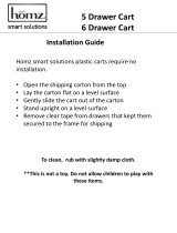
The Anti-Clip limiters are enabled by moving
the rear-panel Limiter switch to the “IN” posi-
tion (see Figure 5.1).
5.1.2 High-Pass Filters
Very low frequency signals contain no useful
musical energy, waste valuable amplifi er power
and headroom, and can be damaging to
5 Advanced Features
and Options
your speakers. Your Crown amplifi er provides
switchable high-pass fi lters to remove these
signals from each channel’s output.
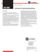
For each channel, a back-panel, three-position
switch provides optional settings of 30 Hz
(left), 15 Hz (center), or OFF (right) (see Figure
5.2). The 30 Hz setting is suitable for all full-
range and low-frequency applications. The 15
Hz setting may be selected when the amplifi er
is being used to drive a sub-bass program;
use only with speakers that provide a useful
frequency response below 30 Hz. The OFF set-
ting provides bypass of the high-pass fi lters,
for use when subsonic protection is provided
elsewhere in the system.
5.1.3 Output Current Limiting
Output Current Limiting circuitry protects the
amplifi er output stage from damage caused by
short circuit loads.
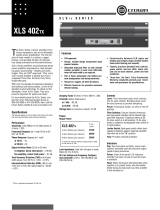
5.1.4 DC Protection
DC Protection disconnects the loudspeaker
load in the event of an output DC offset exceed-
ing 2V. In such an
event the yellow Fault LED
will illuminate (see Figure 5.3) and both amplifi er
channels will be muted. In the majority of
cases,
DC protection is indicative of a faulty amplifi er
channel, and will be accompanied by an illumi-
nated Clip LED, even with no input connected
and level controls set at minimum. If this is the
case, contact your dealer or service center.
5.1.5 Fuse
The high-voltage power supplies of your
Crown amplifi er are protected by a fuse. The
fuse rating varies depending on model and
supply voltage as follows.
230V 120V
XLS202 T6.3A T6.3A
XLS402 T6.3A T10A
XLS602 T6.3A T10A
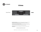
The fuse rating for your amplifi er will also
be indicated on the amplifi er back panel label
below the power connector (see Figure 5.4).
Crown amplifi ers do not blow their fuses
unless something is wrong. Repeated fuse
failure typically indicates problems with the
amplifi er or installation which should be cor-
rected immediately.
Should the fuse need to be replaced, take care
to follow these precautions:
1. Remove power before replacing.
2. Never replace the fuse with a higher rating
than specifi ed; this could result in a
re hazard.
3. IMPORTANT: The orientation of the fuse
drawer determines the operating voltage of
your amplifi er. Should the fuse need to
be replaced, take care to replace the fuse
drawer so that the voltage numbers dis-
played on the top, left corner of the drawer
are correct for your local supply.
5.1.6 Thermal Protection
The Thermal Protection circuit will activate
should the internal heatsink temperature
exceed proper operating temperatures (194
degrees F, 90 degrees C). When the heatsink
temperature has fallen to a safe level, this
protection circuit will automatically be reset.
Principle causes of thermal protection are: 1)
Inadequate ventilation of the equipment rack;
2) Incorrect load impedance; 3) Output cable
short circuit; 4) Blocked air vent; 5) Heatsinks
in need of cleaning; 6) Cooling fan failure.
The cause of your amplifi er’s thermal protection
state should be determined and corrected as
soon as possible. Without correction, the Ther-
mal Protection circuit will typically reactivate.
Figure 5.1 Anti-
Clip Limiter switch
Figure 5.2 High-
Pass Filter switch
Figure 5.4 Ampli-
er fuse rating
Figure 5.3 Fault
indicator
XLS Series Power Amplifi ers
Operation Manual
page 12
CONDITION: Normal operation.
POSSIBLE REASON:
This is normal operation for your amp.
CONDITION: No power to the
amplifi er.
POSSIBLE REASON:
The amplifi er’s “power” switch is off.
The amplifi er is not plugged into the
power receptacle.
The amplifi er’s high-voltage power
supply fuse has blown. Refer to the
Advanced Features and Options section
of this manual for instruction on fuse
replacement.
CONDITION: Distorted sound.
POSSIBLE REASON:
Input signal level is too high. Enable
“anti-clip” Limiter switch. If Clip indi-
cators continue to illuminate frequently,
turn down your amplifi er level controls.
NOTE: Your amplifi er should never be
operated at a level which causes the Clip
LEDs to illuminate constantly.
6 Troubleshooting
KEY
CONDITION: No sound.
POSSIBLE REASON:
The amplifi er has just been turned on and
is still in the 4-second turn-on delay.
The amplifi er is in “fault” mode. A Fault
status can be triggered when one of the
amplifi er’s protection circuits is activated.
First disconnect your speakers from the
affected channel(s) one by one to deter-
mine if one of the loads is shorted. If the
indicators return to normal status, then
try a different speaker or cable to deter-
mine where the short is occurring. If no
short can be found, turn off the amp and
allow the amp to cool. If indicators do not
return to normal after restarting your amp,
check the fuse and replace if necessary,
or return amp to Crown or an authorized
Crown Service Center for servicing.
No input signal.
Input signal level is very low.
Level controls are turned down.
• Speakers not connected.
XLS Series Power Amplifi ers
Operation Manual
page 13
120 VAC, 60 Hz Units, per channel, both channels driven
1 kHz with 0.1% THD
Stereo, 2 ohm (per ch.) 250 570 840
Stereo, 4 ohm (per ch.) 200 400 600
Stereo, 8 ohm (per ch.) 145 260 370
240 VAC, 50 Hz Units, per channel, both channels driven
1 kHz with 0.1% THD
Stereo, 2 ohm (per ch.) 260 610 880
Stereo, 4 ohm (per ch.) 225 445 670
Stereo, 8 ohm (per ch.) 155 275 400
Performance XLS202 XLS402 XLS602
Sensitivity (volts RMS)
for full rated power at 4 ohms 0.725 1.025 1.26
Frequency Response (at 1 watt) 20Hz - 20kHz ± 0.75 dB ± 0.75 dB ± 0.75 dB
Phase Response (degrees at 1 watt)
at 10 Hz –10 –10 –10
at 20 kHz +19 +19 +19
Signal to Noise Ratio (20 Hz to 20 kHz)
A-weighted, below rated power > 100 dB > 100 dB > 100 dB
No weighting, below rated power > 97 dB > 97 dB > 97 dB
Total Harmonic Distortion (THD)
at full bandwidth power, from 20 Hz to 1 kHz < 0.15% < 0.15% < 0.15%
Intermodulation Distortion (IMD)
60 Hz and 7 kHz at 4:1, from full rated output to –40 dB < 0.3% < 0.3% < 0.3%
Damping Factor (8 ohm) 10Hz to 400Hz > 200 > 200 > 200
Crosstalk, below rated power
at 1 kHz –82 dB –82 dB –82 dB
at 20 kHz –58 dB –58 dB –58 dB
Input Impedance
nominally balanced, nominally unbalanced 20 k ohms, 10 k ohms 20 k ohms, 10 k ohms 20 k ohms, 10 k ohms
Load Impedance (rated)
Note: Safe with all types of loads.
Stereo 2-8 ohms 2-8 ohms 2-8 ohms
Bridge-Mono 8 ohms 8 ohms 8 ohms
Voltage Gain (at maximum output) 31 dB 31 dB 31 dB
AC Line Voltage and Frequency Confi gurations Available (±10%) 120 VAC/60 Hz and 230 VAC/50 Hz 120 VAC/60 Hz and 230 VAC/50 Hz 120 VAC/60 Hz and 230 VAC/50 Hz
7 Specifi cations
Minimum Guaranteed Power (watts) XLS202 XLS402 XLS602
XLS Series Power Amplifi ers
Operation Manual
page 14
7 Specifi cations
Construction All Models
Ventilation Flow-through ventilation from front to back.
Cooling Internal heat sinks with forced-air cooling for rapid, uniform heat dissipation.
Air Volume Requirements (per minute per unit) 80.15 ft³ (2.27 m³)
Dimensions
Width EIA Standard 19-inch rack mount (EIA RS-310-B);
Height 5.25 inch (13.3 cm)
Depth (behind mounting surface) 12.6 inch (32.0 cm).
Weight XLS202 XLS402 XLS602
Net Weight 30 lbs. (13.6 kg) 31 lbs. (14.0 kg) 33 lbs. (15.0 kg)
Shipping Weight 37 lbs. (16.8 kg) 38 lbs. (17.2 kg) 42 lbs. (19 kg)
XLS Series Power Amplifi ers
Operation Manual
page 15
Crown amplifi ers are quality units that rarely
require servicing. Before returning your unit
for servicing, please contact Crown Technical
Support to verify the need for servicing.
This unit has very sophisticated circuitry which
should only be serviced by a fully trained tech-
nician. This is one reason why each unit bears
the following label:
CAUTION: To prevent electric shock, do
not remove covers. No user serviceable
parts inside. Refer servicing to a quali-
ed technician.
8.1 Worldwide Service
Service may be obtained from an authorized
service center. (Contact your local Crown/
Amcron representative or our offi ce for a list
of authorized service centers.) To obtain ser-
vice, simply present the bill of sale as proof
of purchase along with the defective unit to an
authorized service center. They will handle the
necessary paperwork and repair.
Remember to transport your unit in the original
factory pack.
8.2 US and Canada Service
Service may be obtained from the factory. It is
important that you have your copy of the bill of
sale as your proof of purchase.
8.2.1 Factory Service
To obtain factory service, fi ll out the service
information page found in the back of this
manual and send it along with your proof of
purchase and the defective unit to the Crown
factory.
For warranty service, we will pay for ground
shipping both ways in the United States. Con-
tact Crown Factory Service or Technical Sup-
port to obtain prepaid shipping labels prior to
sending the unit. Or, if you prefer, you may
prepay the cost of shipping, and Crown will
reimburse you. Send copies of the shipping
receipts to Crown to receive reimbursement.
Your repaired unit will be returned via UPS
ground. Please contact us if other arrange-
ments are required.
Factory Service Shipping Instructions:
1. Before sending a Crown product to the
factory for service, fi rst call the Crown
Service Department for a return authori-
zation (RA) number.
2. Be sure to fi ll out the service information
form that follows and enclose it with
your shipment, either inside the box
or in a packing slip envelope securely
attached to the outside of the shipping
carton. Do not send the service informa-
tion form separately.
3. To ensure the safe transportation of your
unit to the factory, ship it in an original
factory packing container. If you don’t
have the original carton, you may obtain
a product service foam-in-place ship-
ping pack from the Crown Factory Ser-
vice Department at the number listed
below. For non-warranty service, you
may also provide your own shipping
pack. Minimum recommended require-
ments for materials are as follows: 275
8 Service
P.S.I. burst test Double-Wall carton that
allows for 2-inch solid Styrofoam on
all six sides of unit or 3 inches of
plastic bubble wrap on all six sides of
unit; securely seal the package with an
adequate carton sealing tape. Do not
use light boxes or “peanuts.” Damage
caused by poor packing cannot be cov-
ered under warranty.
4. Do not ship the unit in any kind of cabi-
net (wood or metal). Ignoring this warn-
ing may result in extensive damage to
the unit and the cabinet. Accessories are
not needed—do not send the product
documentation, cables and other hard-
ware.
If you have any questions, please call or write
the Crown Technical Support Group.
Crown Customer Service
Technical Support / Factory Service
Plant 2 SW, 1718 W. Mishawaka Rd.,
Elkhart, Indiana 46517 U.S.A.
Telephone: 574-294-8200
800-342-6939 (North America,
Puerto Rico, and Virgin Islands only)
Facsimile:
574-294-8301 (Technical Support)
574-294-8124 (Factory Service)
Internet:
http://www.crownaudio.com
XLS Series Power Amplifi ers
Operation Manual
page 16
YEAR
3
9 Warranty
UNITED STATES & CANADA
SUMMARY OF WARRANTY
Crown International, 1718 West Mishawaka
Road, Elkhart, Indiana 46517-4095 U.S.A.
warrants to you, the ORIGINAL PURCHASER
and ANY SUBSEQUENT OWNER of each
NEW Crown product, for a period of three
(3) years from the date of purchase by the
original purchaser (the “warranty period”)
that the new Crown product is free of
defects in materials and workmanship. We
further warrant the new Crown product
regardless of the reason for failure, except
as excluded in this Warranty.
ITEMS EXCLUDED FROM THIS
CROWN WARRANTY
This Crown Warranty is in effect only for fail-
ure of a new Crown product which occurred
within the Warranty Period. It does not
cover any product which has been damaged
because of any intentional misuse, accident,
negligence, or loss which is covered under
any of your insurance contracts. This Crown
Warranty also does not extend to the new
Crown product if the serial number has been
defaced, altered, or removed.
WHAT THE WARRANTOR WILL DO
We will remedy any defect, regardless of the
reason for failure (except as excluded), by
repair, replacement, or refund. We may not
elect refund unless you agree, or unless we
are unable to provide replacement, and repair
is not practical or cannot be timely made. If
a refund is elected, then you must make the
defective or malfunctioning product available
to us free and clear of all liens or other encum-
brances. The refund will be equal to the actual
purchase price, not including interest, insur-
ance, closing costs, and other fi nance charges
less a reasonable depreciation on the product
from the date of original purchase. Warranty
work can only be performed at our authorized
service centers or at the factory. Warranty work
for some products can only be performed at
our factory. We will remedy the defect and ship
the product from the service center or our fac-
tory within a reasonable time after receipt of
the defective product at our authorized service
center or our factory. All expenses in remedy-
ing the defect, including surface shipping costs
in the United States, will be borne by us. (You
must bear the expense of shipping the product
between any foreign country and the port of
entry in the United States including the return
shipment, and all taxes, duties, and other cus-
toms fees for such foreign shipments.)
HOW TO OBTAIN WARRANTY
SERVICE
You must notify us of your need for warranty
service within the warranty period. All com-
ponents must be shipped in a factory pack,
which, if needed, may be obtained from us
free of charge. Corrective action will be taken
within a reasonable time of the date of receipt
of the defective product by us or our autho-
rized service center. If the repairs made by us
or our authorized service center are not satis-
factory, notify us or our authorized service
center immediately.
DISCLAIMER OF CONSEQUENTIAL
AND INCIDENTAL DAMAGES
YOU ARE NOT ENTITLED TO RECOVER FROM
US ANY INCIDENTAL DAMAGES RESULTING
FROM ANY DEFECT IN THE NEW CROWN
PRODUCT. THIS INCLUDES ANY DAMAGE TO
ANOTHER PRODUCT OR PRODUCTS RESULT-
ING FROM SUCH A DEFECT. SOME STATES
DO NOT ALLOW THE EXCLUSION OR LIMITA-
TIONS OF INCIDENTAL OR CONSEQUENTIAL
DAMAGES, SO THE ABOVE LIMITATION OR
EXCLUSION MAY NOT APPLY TO YOU.
WARRANTY ALTERATIONS
No person has the authority to enlarge, amend,
or modify this Crown Warranty. This Crown
Warranty is not extended by the length of time
which you are deprived of the use of the new
Crown product. Repairs and replacement parts
provided under the terms of this Crown War-
ranty shall carry only the unexpired portion of
this Crown Warranty.
DESIGN CHANGES
We reserve the right to change the design
of any product from time to time without
notice and with no obligation to make cor-
responding changes in products previously
manufactured.
LEGAL REMEDIES OF PURCHASER
THIS CROWN WARRANTY GIVES YOU SPE-
CIFIC LEGAL RIGHTS, YOU MAY ALSO
HAVE OTHER RIGHTS WHICH VARY FROM
STATE TO STATE. No action to enforce this
Crown Warranty shall be commenced after
expiration of the warranty period.
THIS STATEMENT OF WARRANTY SUPER-
SEDES ANY OTHERS CONTAINED IN THIS
MANUAL FOR CROWN PRODUCTS.
XLS Series Power Amplifi ers
Operation Manual
page 17
YEAR
3
9 Warranty
WORLDWIDE EXCEPT USA & CANADA
SUMMARY OF WARRANTY
Crown International, 1718 West Mishawaka
Road, Elkhart, Indiana 46517-4095 U.S.A.
warrants to you, the ORIGINAL PURCHASER
and ANY SUBSEQUENT OWNER of each
NEW Crown
1
product, for a period of three
(3) years from the date of purchase by the
original purchaser (the “warranty period”)
that the new Crown product is free of defects
in materials and workmanship, and we fur-
ther warrant the new Crown product regard-
less of the reason for failure, except as
excluded in this Warranty.
ITEMS EXCLUDED FROM THIS
CROWN WARRANTY
This Crown Warranty is in effect only for fail-
ure of a new Crown product which occurred
within the Warranty Period. It does not
cover any product which has been damaged
because of any intentional misuse, accident,
negligence, or loss which is covered under
any of your insurance contracts. This Crown
Warranty also does not extend to the new
Crown product if the serial number has been
defaced, altered, or removed.
WHAT THE WARRANTOR WILL DO
We will remedy any defect, regardless of
the reason for failure (except as excluded),
by repair, replacement, or refund. We may
not elect refund unless you agree, or unless
we are unable to provide replacement, and
repair is not practical or cannot be timely
made. If a refund is elected, then you must
make the defective or malfunctioning prod-
uct available to us free and clear of all
liens or other encumbrances. The refund will
be equal to the actual purchase price, not
including interest, insurance, closing costs,
and other finance charges less a reasonable
depreciation on the product from the date of
original purchase. Warranty work can only
be performed at our authorized service cen-
ters. We will remedy the defect and ship
the product from the service center within a
reasonable time after receipt of the defective
product at our authorized service center.
HOW TO OBTAIN WARRANTY
SERVICE
You must notify your local Crown importer
of your need for warranty service within
the warranty period. All components must
be shipped in the original box. Corrective
action will be taken within a reasonable
time of the date of receipt of the defective
product by our authorized service center. If
the repairs made by our authorized service
center are not satisfactory, notify our autho-
rized service center immediately.
DISCLAIMER OF CONSEQUENTIAL
AND INCIDENTAL DAMAGES
YOU ARE NOT ENTITLED TO RECOVER FROM
US ANY INCIDENTAL DAMAGES RESULTING
FROM ANY DEFECT IN THE NEW CROWN
PRODUCT. THIS INCLUDES ANY DAMAGE TO
ANOTHER PRODUCT OR PRODUCTS RESULT-
ING FROM SUCH A DEFECT.
WARRANTY ALTERATIONS
No person has the authority to enlarge, amend,
or modify this Crown Warranty. This Crown
Warranty is not extended by the length of time
which you are deprived of the use of the new
Crown product. Repairs and replacement parts
provided under the terms of this Crown War-
ranty shall carry only the unexpired portion of
this Crown Warranty.
DESIGN CHANGES
We reserve the right to change the design of
any product from time to time without notice
and with no obligation to make corresponding
changes in products previously manufactured.
LEGAL REMEDIES OF PURCHASER
No action to enforce this Crown Warranty
shall be commenced after expiration of the
warranty period.
THIS STATEMENT OF WARRANTY SUPER-
SEDES ANY OTHERS CONTAINED IN THIS
MANUAL FOR CROWN PRODUCTS.
_______________
1 Note: If your unit bears the name “Amcron,” please
substitute it for the name “Crown” in this warranty.
XLS Series Power Amplifi ers
Operation Manual
page 18
Notes
XLS Series Power Amplifi ers
Operation Manual
page 19
Crown Factory Service Information
Shipping Address: Crown International, Factory Service, Plant 2 SW, 1718 W. Mishawaka Rd., Elkhart, IN 46517
Phone: 1-800-342-6939 or 1-574-294-8200 Fax: 1-574-294-8124
Owner’s Name : ___________________________________________________________________________________________________________________________________________________________________________
Shipping Address : _________________________________________________________________________________________________________________________________________________________________________
Phone Number: __________________________________________________________________________________________ Fax Number: _____________________________________________________________________
Model: ______________________________________________________________________________________________ Serial Number: ___________________________________________________________________
Purchase Date : ___________________________________________________________________________________________________________________________________________________________________________
NATURE OF PROBLEM
(Be sure to describe the conditions that existed when the problem occurred and what attempts were made to correct it.)
_____________________________________________________________________________________________________________________________________________________________________________
_____________________________________________________________________________________________________________________________________________________________________________
_____________________________________________________________________________________________________________________________________________________________________________
_____________________________________________________________________________________________________________________________________________________________________________
_____________________________________________________________________________________________________________________________________________________________________________
_____________________________________________________________________________________________________________________________________________________________________________
_____________________________________________________________________________________________________________________________________________________________________________
_____________________________________________________________________________________________________________________________________________________________________________
_____________________________________________________________________________________________________________________________________________________________________________
Other equipment in system: ______________________________________________________________________________________________________________________________________________________
_____________________________________________________________________________________________________________________________________________________________________________
_____________________________________________________________________________________________________________________________________________________________________________
_____________________________________________________________________________________________________________________________________________________________________________
If warranty has expired, payment will be:
Cash/Check VISA MasterCard C.O.D.
Card Number:______________________________________ Exp. Date:___________________
Signature:______________________________________________________________________
ENCLOSE THIS PORTION WITH THE UNIT. DO NOT MAIL SEPARATELY.
  • Page 1 1
  • Page 2 2
  • Page 3 3
  • Page 4 4
  • Page 5 5
  • Page 6 6
  • Page 7 7
  • Page 8 8
  • Page 9 9
  • Page 10 10
  • Page 11 11
  • Page 12 12
  • Page 13 13
  • Page 14 14
  • Page 15 15
  • Page 16 16
  • Page 17 17
  • Page 18 18
  • Page 19 19
  • Page 20 20

Crown XLS 202 Operating instructions

Category
Supplementary music equipment
Type
Operating instructions
This manual is also suitable for

Crown XLS 202 is a reliable and affordable power amplifier that delivers 350 watts of power per channel into 8 ohms, ideal for powering speakers in a variety of applications. With its simple design, it offers XLR inputs, touch-proof binding post outputs, and features like anti-clip limiters, high-pass filters, and protection systems for safe and efficient operation.

Ask a question and I''ll find the answer in the document

Finding information in a document is now easier with AI