Page is loading ...
Page is loading ...
Page is loading ...

3
Svenska Dansk Norsk Suomi English
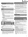
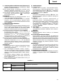
3,6 volts
3,6 V genopladeligt 3,6 V oppladbart 3,6 V ladattava 3.6 V Rechargeable
uppladdningsbart
batteri batteri paristo battery
batteri
Polhål Tilslutningshul Terminal hull Liitäntäaukko Terminal hole
Frigöringsknapp för
Batterifrigørelsesknap
Batteriutløserknapp
Akun Battery release
batteri vapautuspainike button
Dra ut Træk ud Dra ut Ota ulos Pull out
Passa in Ilæg Sett i Paina sisään Insert
Handtag Håndtag Håndtak Kahva Handle
Passa in Ilæg Sett i Paina sisään Insert
Signallampa Kontrollampe Pilot-lys Markkivalo Pilot lamp
Hål för iläggning Hul til tilslutning af Hull for tilkopling av
Ladattavan pariston
Hole for connecting
av det uppladdnings-
det opladelige det oppladbare
liitäntäaukko
the rechargeable
bara batteriet batteri batteriet battery
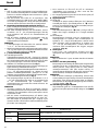
Skruvdragarspets Skruetrækkerbits Skrutrekkerbits Taltan terä Driver bit
Rörelseriktning Bevægelse Bevegelse Liike Movement
Styrhylsa Muffe Førehylse Ohjainhylsy Guide sleeve
Sexkanthåi i hylsan Sekskantet hul i Sekskanthull i hylsen
Istukan kuusiokulmainen
Hexagonal hole in
receptoren
aukko
the socket
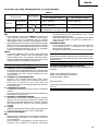
Hastighetsomkopplare
Omskifterknap Omskifterbryter Liukunäppäin Shift knob
Låg hastighet Lav hastighed Lav hastighet Hidas Low speed
Hög hastighet Høj hastighed Høy hastighet Nopea High speed
Borrläge Boremærkning Bormerke Porausmerkki Drill mark
Momentinställning Koblingsskive Justeringsring Kytkimen valitsin Clutch dial
Triangelmärke Trekantmærke Trekantmerke Kolmikulmiomerkki Triangle mark
Svag
Svag Svak Kevyt Weak
åtdragningskraft
Stark
Stærk Sterk Vahva Strong
åtdragningskraft
Svart linje Sort linje Svart linje Musta viiva Black line
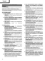
Låsomkopplare Låsekontakt Låsbryter Lukituskatkaisin Lock switch
Olåst Lås op Åpne Vapauta lukko Unlock
Låst Lås Lås Lukitse Lock
䊲 Låst 䊲 Lås 䊲 Lås 䊲 lukko 䊲 Lock
Huvudomkopplare Hovedafbryder Hovedbryter Pääkytkin Main switch
Ljusomkopplare Lyskontakt Lysbryter Valokatkaisija Light switch
Böjlig del Bøjelig del Dreibar del Taitettava osa Bending portion
1
2
3
4
5
6
7
8
9
0
A
B
C
D
E
F
G
H
I
J
K
L
M
N
O
P
Q
R
S
Page is loading ...
Page is loading ...
Page is loading ...
Page is loading ...
Page is loading ...
Page is loading ...
Page is loading ...
Page is loading ...
Page is loading ...
Page is loading ...
Page is loading ...
Page is loading ...
Page is loading ...
Page is loading ...
Page is loading ...
Page is loading ...
Page is loading ...
Page is loading ...
Page is loading ...
Page is loading ...

English
24
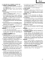
GENERAL SAFETY RULES
WARNING!
Read all instructions
Failure to follow all instructions listed below may result in
electric shock, fire and/or serious injury.
The term “power tool” in all of the warnings listed below
refers to your mains operated (corded) power tool or battery
operated (cordless) power tool.
SAVE THESE INSTRUCTIONS
1) Work area
a) Keep work area clean and well lit.
Cluttered and dark areas invite accidents.
b) Do not operate power tools in explosive
atmospheres, such as in the presence of flammable
liquids, gases or dust.
Power tools create sparks which may ignite the
dust of fumes.
c) Keep children and bystanders away while operating
a power tool.
Distractions can cause you to lose control.
2) Electrical safety
a) Power tool plugs must match the outlet.
Never modify the plug in any way.
Do not use any adapter plugs with earthed
(grounded) power tools.
Unmodified plugs and matching outlets will reduce
risk of electric shock.
b) Avoid body contact with earthed or grounded
surfaces such as pipes, radiators, ranges and
refrigerators.
There is an increased risk of electric shock if your
body is earthed or grounded.
c) Do not expose power tools to rain or wet
conditions.
Water entering a power tool will increase the risk
of electric shock.
d) Do not abuse the cord. Never use the cord for
carrying, pulling or unplugging the power tool.
Keep cord away from heat, oil, sharp edges or
moving parts.
Damaged or entangled cords increase the risk of
electric shock.
e) When operating a power tool outdoors, use an
extension cord suitable for outdoor use.
Use of a cord suitable for outdoor use reduces
the risk of electric shock.
3) Personal safety
a) Stay alert, watch what you are doing and use
common sense when operating a power tool.
Do not use a power tool while you are tired or
under the influence of drugs, alcohol or medication.
A moment of inattention while operating power
tools may result in serious personal injury.
b) Use safety equipment. Always wear eye protection.
Safety equipment such as dust mask, non-skid
safety shoes, hard hat, or hearing protection used
for appropriate conditions will reduce personal
injuries.
c) Avoid accidental starting. Ensure the switch is in
the off position before plugging in.
Carrying power tools with your finger on the
switch or plugging in power tools that have the
switch on invites accidents.
d) Remove any adjusting key or wrench before
turning the power tool on.
A wrench or a key left attached to a rotating part
of the power tool may result in personal injury.
e) Do not overreach. Keep proper footing and balance
at all times.
This enables better control of the power tool in
unexpected situations.
f) Dress properly. Do not wear loose clothing or
jewellery. Keep your hair, clothing and gloves
away from moving parts.
Loose clothes, jewellery or long hair can be caught
in moving parts.
g) If devices are provided for the connection of dust
extraction and collection facilities, ensure these
are connected and properly used.
Use of these devices can reduce dust related hazards.
4) Power tool use and care
a) Do not force the power tool. Use the correct
power tool for your application.
The correct power tool will do the job better and
safer at the rate for which it was designed.
b) Do not use the power tool if the switch does not
turn it on and off.
Any power tool that cannot be controlled with the
switch is dangerous and must be repaired.
c) Disconnect the plug from the power source before
making any adjustments, changing accessories, or
storing power tools.
Such preventive safety measures reduce the risk
of starting the power tool accidentally.
d) Store idle power tools out of the reach of children
and do not allow persons unfamiliar with the
power tool or these instructions to operate the
power tool.
Power tools are dangerous in the hands of
untrained users.
e) Maintain power tools. Check for misalignment or
binding of moving parts, breakage of parts and
any other condition that may affect the power
tools operation.
If damaged, have the power tool repaired before
use.
Many accidents are caused by poorly maintained
power tools.
f) Keep cutting tools sharp and clean.
Properly maintained cutting tools with sharp cutting
edges are less likely to bind and are easier to
control.
g) Use the power tool, accessories and tool bits etc.,
in accordance with these instructions and in the
manner intended for the particular type of power
tool, taking into account the working conditions
and the work to be performed.
Use of the power tool for operations different from
intended could result in a hazardous situation.
5) Service
a) Have your power tool serviced by a qualified repair
person using only identical replacement parts.
This will ensure that the safety of the power tool
is maintained.
PRECAUTION
Keep children and infirm persons away.
When not in use, tools should be stored out of reach of
children and infirm persons.

English
25
SPECIFICATIONS
POWER TOOL
STANDARD ACCESSORIES
1 Plus driver bit (No. 2 × 50L)............................... 1
2 Battery (EBM315)...................................................... 1
3 Charger
(UC3SFL) ............................................................
1
4 Plastic case................................................................ 1
Standard accessories are subject to change without
notice.
OPTIONAL ACCESSORIES (sold separately)
1. Battery (EBM315)
Optional accessories are subject to change without notice.
No-load speed (Low/High) 200 / 600 min
–1
Drilling
Metal Steel: 2 mm,
(Thickness 1.0 mm) Aluminum: 2 mm
Capacity Machine screw 5 mm
Driving
Wood screw
3.5 mm (diameter) × 20 mm (length)
(Requires a pilot hole)
Rechargeable battery EBM315: Li-ion 3.6 V (1.5 Ah 1 cell)
Weight 0.4 kg
APPLICATIONS
䡬 Driving and removing of machine screws, wood
screws, tapping screws, etc.
䡬 Drilling of various metals
BATTERY REMOVAL/INSTALLATION
1. Battery removal
Hold the handle tightly and push the battery release
buttons (2 pcs.) to remove the battery (see Figs. 1 and
2).
CAUTION:
Never short-circuit the battery.
2. Battery installation
Insert the battery while observing its polarities (see
Fig. 2).
CHARGING
Before using the driver drill, charge the battery as follows.
1. Connect the charger’s power cord to a receptacle.
2. Insert the battery into the charger.
Firmly insert the battery into the charger till it contacts
the bottom of the charger and checking the polarities
as shown in Fig. 3.
CHARGER
Model UC3SFL
Charging voltage 3.6 V
Weight 0.3 kg
PRECAUTIONS FOR CORDLESS DRIVER
DRILL
1. Always charge the battery at a temperature of 10 –
40°C. A temperature of less than 10°C will result in
over charging which is dangerous. The battery
cannot be charged at a temperature higher than
40°C.
The most suitable temperature for charging is that
of 20 – 25°C.
2. When one charging is completed, leave the charger
for about 15 minutes before the next charging of
battery.
Do not charge more than two batteries
consecutively.
3. Do not allow foreign matter to enter the hole for
connecting the rechargeable battery.
4. Never disassemble the rechargeable battery and
charger.
5. Never short-circuit the rechargeable battery. Short-
circuiting the battery will cause a great electric
current and overheat. It results in burn or damage
to the battery.
6. Do not dispose of the battery in fire.
If the battery is burnt, it may explode.
7. When drilling in wall, floor or ceiling, check for
buried electric power cord, etc.
8. Bring the battery to the shop from which it was
purchased as soon as the post-charging battery life
becomes too short for practical use. Do not dispose
of the exhausted battery.
9. Using an exhausted battery will damage the charger.
10. Do not insert object into the air ventilation slots of
the charger.
Inserting metal objects or inflammables into the
charger air ventilation slots will result in electrical
shock hazard or damaged charger.

English
26
Inserting the battery will turn on the charger (the
pilot lamp lights up).
CAUTION
If the pilot lamp does not light up, pull out the
power cord from the receptacle and check the
battery mounting condition.
The pilot lamp goes off to indicate that the battery is
fully charged.
CAUTION
If the battery is heated due to direct sunlight, etc.,
just after operation, the charger pilot lamp may
not light. At that time cool the battery first, then
start charging.
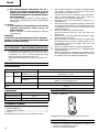
䡬 Regarding recharging time
Table 1 shows the recharging time required according
to the type of battery.
NOTE: The recharging time may vary according to the
ambient temperature.
3. Disconnect the charger’s power cord from the
receptacle.
4. Hold the charger firmly and pull out the battery.
NOTE:
After operation, pull out batteries from the charger
first, and then keep the batteries properly.
Regarding electric discharge in case of new
batteries, etc.
As the internal chemical substance of new batteries
and batteries that have not been used for an extended
period is not activated, the electric discharge might
be low when using them the first and second time.
This is a temporary phenomenon, and normal time
required for recharging will be restored by recharging
the batteries 2 – 3 times.
How to make the batteries perform longer
(1) Recharge the batteries before they become completely
exhausted.
When you feel that the power of the tool becomes
weaker, stop using the tool and recharge its battery.
If you continue to use the tool and exhaust the electric
current, the battery may be damaged and its life will
become shorter.
(2) Avoid recharging at high temperatures.
A rechargeable battery will be hot immediately after
use. If such a battery is recharged immediately after
use, its internal chemical substance will deteriorate,
and the battery life will be shortened. Leave the battery
and recharge it after it has cooled for a while.
CAUTION:
䡬 When the battery charger has been continuously used,
the battery charger will be heated, thus constituting
the cause of the failures. Once the charging has been
completed, give 15 minutes rest until the next
charging.
䡬 If the battery charger does not work while the battery
is mounted correctly, it is probable that the battery or
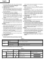
Table 1 Recharging time (approx. min.) at 20°C
Battery
voltage
(V)
Battery capacity (Ah)
1.5 Ah
3.6 V EBM315 30 min.
charger is malfunctioning. Take it to your authorized
Service Center.
PRIOR TO OPERATION
1. Setting up and checking the work environment
Check if the work environment is suitable by following
the precautions.
HOW TO USE
How to make the batteries perform longer
䡬 Recharge the batteries before they become completely
exhausted.
When you feel that the power of the tool becomes
weaker, stop using the tool and recharge its battery.
If you continue to use the tool and exhaust the electric
current, the battery may be damaged and its life will
become shorter.
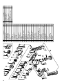
1. Installing the bit
Always follow the following procedure to install driver
bit. (Fig. 4)
(1) Pull the guide sleeve forward.
(2) Insert the bit into the hexagonal hole in the socket.
(3) Release the guide sleeve and it returns to its original
position.
CAUTION:
If the guide sleeve does not return to its original
position, then the bit is not installed properly.
2. Removing the bit
Please do the opposite point on the method of
installing bit.
3. Automatic spindle-lock mechanism
When the main switch is off, the bit is locked in place,
and the tool can be used as a manual screwdriver.
4. Confirm that the battery is mounted correctly
5. Change rotation speed
Operate the shift knob to change the rotational speed.
Move the shift knob in the direction of the arrow (see
Figs. 5 and 6).
When the shift knob is set to “LOW”, the drill rotates
at a low speed. When set to “HIGH”, the drill rotates
at a high speed.
CAUTION:
䡬 When changing the rotational speed with the shift
knob, confirm that the switch is off.
Changing the speed while the motor is rotating will
damage the gears.
䡬 When a large force is required for operation, set the
shift knob to “LOW”. If “HIGH” is set and the unit is
used, it may cause the motor to burn out or
malfunction prematurely.
6. Confirm the clutch dial position (See Fig. 7)
The tightening torque of this unit can be adjusted
according to the clutch dial position, at which the
clutch dial is set.
(1) When using this unit as a screwdriver, line up the one
of the numbers “1, 5, 9 ... 21” on the clutch dial, or the
black dots, with the triangle mark on the outer body.
(2) When using this unit as a drill, align the clutch dial
drill mark “
” with the triangle mark on the outer
body.
CAUTION
䡬 The clutch dial cannot be set between the numerals
“1, 5, 9 ... 21” or the black dots.

English
27
䡬 Do not use with the clutch dial numeral between
“22” and the black line at the middle of the drill mark.
Doing so may cause damage (See Fig. 8).
7. Tightening torque adjustment
(1) Tightening torque
Tightening torque should correspond in its intensity
to the screw diameter. When too strong torque is
used, the screw head may be broken or be injured.
Be sure to adjust the clutch dial position according to
the screw diameter.
(2) Tightening torque indication (See Fig. 7)
The tightening torque differs depending on the type
of screw and the material being tightened.
The unit indicates the tightening torque with the
numbers “1, 5, 9 ... 21” on the clutch dial, and a black
dots. The tightening toque at position “1” is the
weakest and the torque is strongest at the highest
number.
(3) Adjusting the tightening torque (See Fig. 7)
Rotate the clutch dial and line up the numbers “1, 5, 9
... 21” on the clutch dial, or the dots, with the triangle
mark on the outer body. Adjust the clutch dial in the
weak or the strong torque direction according to the
torque you need.
CAUTION
䡬 The motor rotation may be locked to cease while the
unit is used as drill. While operating the driver drill,
take care not to lock the motor.
䡬 When setting the shift knob to “HIGH” (high speed)
and the position of the clutch dial is “17” or “22”, it
may happen that the clutch does not engaged and
that the motor is locked. In such a case, please set the
shift knob to “LOW” (low speed).
䡬 If the motor is locked, immediately turn the power
off. If the motor is locked for a while, the motor or
battery may be burnt.
䡬 Too long hammering may cause the screw broken
due to excessive tightening.
8. Switch operation
(1) Lock switch
The tool is equipped with a lock switch. To activate
the main switch lock, move the lock switch to the “䊲
LOCK” position. Move the lock switch to the opposite
position to operate the tool. (Fig. 9)
CAUTION:
Always set the lock switch to the “䊲 LOCK” position
when carrying or storing the tool eliminate
unintentional starting.
(2) Main switch
The main switch functions as a motor switch and
rotational direction selector switch. When the main
switch is pushed to “R” indicated on the main switch,
the bit rotates clockwise. When the main switch is
pushed to “L” indicated on the main switch, the bit
rotates counterclockwise. When the main switch is
released, the tool stops. (Fig. 10)
9. Using the light
The light lights when the light switch is pushed.
When the light switch is pushed again, the light is
turned off. (Fig. 11)
CAUTION:
Do not look directly into the light. Such actions could
result in eye injury.
10. Using in the Straight or Pistol Configuration
Use the tool in the straight configuration when using
in confined spaces. Use it in the pistol configuration
when using in other locations. Select the configuration
that best matches the tool application. When changing
the configuration, the tool will make a clicking sound
when it snaps into position. Bend (or extend) the tool
until the clicking sound is heard.
CAUTION:
When using the tool in the pistol configuration, do
not hold onto the bending portion of the tool when
returning to the straight configuration. Your finger or
other part of the hand may be pinched by the bend
ing portion resulting in possible injury (Fig. 12).
11. The scope and suggestions for uses
The usable scope for various types of work based on
the mechanical structure of this unit is shown in
Table 2.
Work Suggestions
Drilling
Steel
Use for drilling purpose.
Aluminum
Machine screw Use the bit or socket matching the screw diameter.
Driving
Wood screw Use after drilling a pilot hole.
Table 2
12. How to select tightening torque and rotational speed
Table 3
Use Cap Position
Rotating speed selection (Position of the shift knob)
LOW (Low speed) HIGH (High speed)
Machine screw 1 – 21
For 5 mm or smaller diameter
screws
Driving
Wood screw 1 –
For 3.5 mm or smaller nominal
diameter screws
Drilling Metal
For drilling with a metal
working drill bit
For 3 mm or smaller
diameter screws

English
28
CAUTION:
䡬 The selection examples shown in Table 3 should be
considered as general standard. As different types of
tightening screws and different materials to be
tightened are used in actual works proper adjustments
are naturally necessary.
䡬 When using the driver drill with a machine screw at
HIGH (high speed), a screw may damage or a bit may
loose due to the tightning torque is too strong. Use
the driver drill at LOW (low speed) when using a
machine screw.
NOTE:
The use of the battery EBM315 in a cold condition
(below 0 degree Centigrade) can sometimes result in
the weakened tightening torque and reduced amount
of work. This, however, is a temporary phenomenon,
and returns to normal when the battery warms up.
MAINTENANCE AND INSPECTION
1. Inspecting the tool
Since use of as dull tool will degrade efficiency and
cause possible motor malfunction, sharpen or replace
the tool as soon as abrasion is noted.
2. Inspecting the mounting screws
Regularly inspect all mounting screws and ensure
that they are properly tightened. Should any of the
screws be loose, retighten them immediately. Failure
to do so could result in serious hazard.
3. Maintenance of the motor
The motor unit winding is the very “heart” of the
power tool.
Exercise due care to ensure the winding does not
become damaged and/or wet with oil or water.
4. Cleaning on the outside
When the driver drill is stained, wipe with a soft dry
cloth or a cloth moistened with soapy water. Do not
use chloric solvents, gasoline or paint thinner, for
they melt plastics.
5. Storage
Store the driver drill in a place in which the
temperature is less than 40°C and out of reach of
children.
6. Service parts list
CAUTION:
Repair, modification and inspection of Hitachi Power
Tools must be carried out by a Hitachi Authorized
Service Center.
This Parts List will be helpful if presented with the
tool to the Hitachi Authorized Service Center when
requesting repair or other maintenance.
In the operation and maintenance of power tools, the
safety regulations and standards prescribed in each
country must be observed.
MODIFICATIONS:
Hitachi Power Tools are constantly being improved
and modified to incorporate the latest technological
advancements.
Accordingly, some parts may be changed without
prior notice.
NOTE:
Due to HITACHI’s continuing program of research and
development, the specifications herein are subject to
change without prior notice.
Information concerning airborne noise and vibration
The measured values were determined according to
EN60745 and declared in accordance with ISO 4871.
Measured A-weighted sound power level: 71 dB (A)
Measured A-weighted sound pressure level: 60 dB (A)
Uncertainty KpA: 3 dB (A).
Wear ear protection.
The typical weighted root mean square acceleration
value: 3.1 m/s
2
.
Page is loading ...
Page is loading ...
Page is loading ...
Page is loading ...

606
Code No. C99154181
Printed in China
Dansk
OVERENSS TEMMELSESERKLÆRING
Vi eklærer os fuldstændige ansvarlige for, at dette
produkt modsvarer gældende standard eller de
standardiserede dokumenter EN60745, EN55014 og
EN61000 i overensstemmelse med EF-direktiver 73/23/
EØF, 89/336/EØF og 98/37/EF.
Denne erklæring gælder produkter, der er mærket med
CE.
Norsk
EF’s ERKLÆRING OM OVERENSSTEMMELSE
Vi erklærer herved at vi påtar oss eneansvaret for at
dette produktet er i overensstermmelse med normer eller
standardiserte dokumenter EN60745, EN55014 og
EN61000 i samsvar med Rådsdirektiver 73/23/EØS, 89/
336/EØS og 98/37/EF.
Denne erklæringen gjelder produktets påklistrede CE-
merking.
Suomi
EY-ILMOITUS YHDENMUKAISUUDESTA
Yksinomaisella vastuudella vakuutamme, että tämä
tuote vastaa normeja tai normitettuja dokumentteja
EN60745, EN55014 ja EN61000 yhteisön ohjeiden 73/
23/ETY, 89/336/ETY ja 98/37/EY mukaisesti.
Tämä ilmoitus sovelletaan tuotekohtaiseen CE-
merkintään.
English
EC DECLARATION OF CONFORMITY
We declare under our sole responsibility that this product
is in conformity with standards or standardized documents
EN60745, EN55014 and EN61000 in accordance with
Council Directives 73/23/EEC, 89/336/EEC and 98/37/EC.
This declaration is applicable to the product affixed CE
marking.
Representative office in Europe
Hitachi Power Tools Europe GmbH
Siemensring 34, 47877 Willich1, F. R. Germany
Head office in Japan
Hitachi Koki Co., Ltd.
Shinagawa Intercity Tower A, 15-1, Konan 2-chome,
Minato-ku, Tokyo, Japan
30. 6. 2006
K. Kato
Board Director
Svenska
EF-DEKLARATION BETRÄFFANDE LIKFORMIGHET
Vi tillkännagiver med eget ansvar att denna produkt
överensstämmer med standard eller standardiserat
dokument EN60745, EN55014 och EN61000 i enlighet
med råddirektiven 73/23/EØS, 89/336/EØS och 98/37/EF.
Denna deklaration gäller för CE-märkningen pà
produkten.
Hitachi Koki Co., Ltd.
-
 1
1
-
 2
2
-
 3
3
-
 4
4
-
 5
5
-
 6
6
-
 7
7
-
 8
8
-
 9
9
-
 10
10
-
 11
11
-
 12
12
-
 13
13
-
 14
14
-
 15
15
-
 16
16
-
 17
17
-
 18
18
-
 19
19
-
 20
20
-
 21
21
-
 22
22
-
 23
23
-
 24
24
-
 25
25
-
 26
26
-
 27
27
-
 28
28
-
 29
29
-
 30
30
-
 31
31
-
 32
32
-
 33
33
-
 34
34


Ask a question and I''ll find the answer in the document
Finding information in a document is now easier with AI
in other languages
- dansk: Hikoki DB3DL Brugermanual
- svenska: Hikoki DB3DL Användarmanual
- suomi: Hikoki DB3DL Ohjekirja
Related papers
Other documents
-
Bahco BCL33IW2 User manual
-
-
-
-
-
Hitachi DS 10DFL Handling Instructions Manual
-
-
Hitachi DH 14DL Handling Instructions Manual
-
-