Page is loading ...

UNDER-MOUNT HOOD
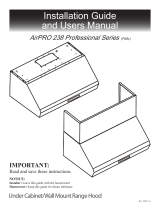
MODEL : AP238-PS15-36
INSTALLATION GUIDE / USE AND CARE MANUAL
IMPORTANT: Read and save these instructions.
Installer: Leave this manual with the homeowner.
Homeowner: Keep this guide for future reference.
2021A


Table of Contents
APPROVED FOR APPLIANCES OF RESIDENTIAL USE
ONLY. READ AND SAVE THESE INSTRUCTIONS.
PLEASE READ THE ENTIRE INSTRUCTIONS BEFORE YOU
BEGIN. INSTALLATION OF THE UNIT MUST RESPECT ALL
CODES.
IMPORTANT: Keep these instructions in order to provide them to the electrical inspector in your area.
INSTALLER: Please leave these instructions with the owner of the unit.
OWNER: Keep these instructions for future reference.
SECURITY WARNING: Turn off the power circuit in the electrical panel and lock the front panel before
connecting the wires of this unit.
Requirements: 2 2 0V , 5 0Hz
3
IMPORTANT SAFETY PRECAUTIONS...................................................................... 4-5
INSTALLATION INSTRUCTIONS............................................................................ 6-13
OPERATING THE HOOD.......................................................................................... 14-16
MAINTENANCE............................................................................................................17-18
WARRANTY......................................................................................................................... 19

IMPORTANT SAFETY PRECAUTIONS
READ AND SAVE THESE
INSTRUCTIONS CAUTION:
For residential use only. Do not use to exhaust hazardous or explosive materials and/or vapors.
CAUTION:
Range hood may have very sharp edges; please wear protective gloves when installing, cleaning or
servicing the unit.
This appliance must be installed by a qualified technician. The manufacturer declines all
responsibility in case of failure to adhere to safety standards. Install this hood in accordance with
all the specified requirements.
WARNING
To reduce the risk of fire, electric shock or injury to persons, observe the following:
manufacturer.
All other servicing should be referred to a qualified technician.
CAUTION:
To reduce risk of fire and to properly exhaust air, be sure to duct air outside - do not vent exhaust air into
spaces within walls, ceilings, attics, crawl spaces, or garages.
Automatically operated device - to reduce risk of injury disconnect from power supply before servicing.
Before servicing or cleaning the unit, switch power off at the service panel and lock the service
disconnecting means stop revent power from being switched on accidentally. If the service
disconnecting means cannot be locked, securely fasten a noticeable warning device, such a tag,
to the service panel.
Use this unit only in the manner intended by the manufacturer. If you have any questions, contact the
Follow the heating equipment manufacturer's guide line and safety standards such as those published
by the National Fire Protection Association (NFPA) and the local code authorities.
equipment to preventback-drafting.
Do not make alterations to the original wiring.
Do not attempt to repair or replace any part of your hood unless it is specifically recommended in this
manual.
Sufficient air is needed for proper combustion and exhausting of gases through the chimney of fuel burning
When cutting or drilling into wall or ceiling, do not damage electrical wiring and other hidden utilities.
Ducted fans must always be vented to the outdoors.
Installation work and electrical wiring must be done by a qualified person in accordance with all
applicalbe codes & standards, including Fire-rated construction.
4

WARNING
TO REDUCE THE RISK OF FIRE, USE ONLY METAL DUCTWORK.
WARNING
TO REDUCE THE RISK OF INJURY TO PERSONS, IN THE EVENT OF A COOKTOP GREASE
FIRE, OBSERVE THE FOLLOWING:
Smother flames with a close-fitting lid, cookie sheet, or metal tray and then turn off the burner.
If the flames do not go out immediately, EVACUATE AND CALL THE FIRE DEPARTMENT.
Never pick up a flaming pan - you may BURN YOURSELF.
DO NOT USE WATER, including wet dishcloths or towels -a violent steam explosion will result.
Use an extinguisher ONLY if:
a) You know you have a class ABC extinguisher, and you already know how tooperate it.
b) The fire is small and contained in the area where it started.
c) The fire department has beencalled.
d) You can fight the fire with your back to anexit.
WARNING
TO REDUCE THE RISK OF A RANGE TOP GREASE FIRE:
Never leave a range unattended.
Boil-overs cause smoke and greasy spillovers that may ignite. Heat oils slowly on low or medium setting.
Always turn hood ON when cooking at high heat.
Clean the unit’s surfaces frequently. Grease can accumulate on fan or filters.
Use proper pan size. Always use cookware appropriate for the size of the surface element.
5

Safety gloves and goggles
Electrical drill
Phillips screwdriver
Flathead screwdriver
Hammer
Adjustable wrench
Sheet metalsheers
Needle nose pliers
Scissors (to cut duct tape)
Duct tape
Marker or pencil
Level
Measuring tape
PARTS INCLUDED
Filter spacer
Filters
Qty: 6 pcs
Hood-mounting
bracket
Grease tunnel
Qty: 6 pcs
(for drywall only)
Qty: 6 pcs
INSTALLATION INSTRUCTIONS
TOOLS NEEDED TO INSTALL THE RANGE HOOD
6

A
Floor to ceiling height variable
B
Floor to counter top height
(standard) 36"
C
Recommended height between
cooking surface and bottom of the
hood
28"-30"
D
Hood height 9.8"
E
Cabinet height N/A
DIMENSIONS FOR 30’’ HOOD
Installation
The information contained herein is based on sources that we believe to be reliable, but is not
guaranteed by us, may be incomplete and/or may change without notice.
Overall Rear Knockout Holes
7

BEFORE INSTALLING THE HOOD
WALL FRAMING FOR ADEQUATE SUPPORT
THIS VENT HOOD IS HEAVY. ADEQUATE STRUCTURE AND SUPPORT MUST BE PROVIDED IN ALL TYPES OF
INSTALLATION. IF MOUNTING ONTO DRY WALL, IT IS RECOMMENDED THAT THE HOOD BE SECURED TO
VERTICAL STUDS IN THE WALL OR TO A HORIZONTAL SUPPORT.
WARNING
BE CAREFUL WHEN INSTALLING THE HOOD, AS IT MAY HAVE SHARP EDGES. WE RECOMMEND THAT YOU
WEAR PROTECTIVE GLOVES.
CAUTION
DO NOT REMOVE THE PROTECTIVE PLASTIC FILM COVERING THE HOOD AT THIS STAGE.
For the most efficient airflow exhaust, use a straight run or as few elbows as possible.
Vent unit to the exterior only.
At least two people are required for installation.
Remove the range hood from the carton packaging and place on a flat surface for assembly.
CAUTION
THIS APPLIANCE SHOULD BE PROPERLYGROUNDED.
The range hood must be connected with copper wire/plug only.
Make sure the unit is connected to an individual, properly grounded circuit.
If the electrical supply does not meet above requirements, call a licensed electrician before proceeding.
Route house wiring as close as possible to the installation location, in the ceiling or back wall.
The hood must be connected to the house wiring in accordance with the local codes and norms.
8

Venting Requirements Height & Clearance
•
Vent system must evacuate to the exterior
(through the roof or side wall).
•
DO NOT terminate the vent system in an
attic or other enclosed area.
•
Use rigid metal/aluminum ventonly.
•
NEVER use plastic vent or plastic vent cover.
•
Always keep the duct clean to ensure
proper airflow.
•
Calculate the following figures
before installation:
1. Distance from the floor to the ceiling.
2. Distance between the floor and the
countertop/cooking surface.
3. Distance between the range hood
and the countertop/cooking surface
which is recommended at 27” to 30’’.
4. Height of hood and duct cover with
the cabinet.
Cabinet
height
Range
hood
height
Range hood
Cabinet
For the most efficient & quiet operation:
•
It is recommended that the range hood be
vented vertically through the roof through
8” (20.3 cm) round metal/aluminum vent or
vented horizontally through the wall
through a rectangular vent measuring 3 ¼’’
x10’’.
•
The size of the vent should be uniform.
•
If venting vertically, do not use more than
three 90° elbows. Do not install two elbows
together.
•
Make sure there is a minimum of 24” (61
cm) of straight vent between the elbows if
more than one elbow is used.
•
The length of vent system and number of
elbows should be kept to a minimum to
provide efficient performance.
•
The vent system must have a damper. If
roof or wall cap has a damper, DO NOT use
damper (if supplied) on top of the range
hood.
•
Use duct tape to seal all joints in the vent
system.
•
Use caulking to seal exterior wall or roof
opening around the cap.
Ceiling
height
36” standard
counter
height
Min: 27”
Max: 30”
Countertop/Cooking
surface
9

Option 1:
Horizontal venting
Wall cap
Option 2:
Vertical venting
Roof cap
IMPORTANT
•
A minimum of 8” round (standard for this range hood) must be used to maintain maximum airflow
efficiency.
•
Always use rigid type metal/aluminum ducts if available to maximize airflow when connecting to
duct provided.
VENTING METHODS
INSTALLATION DIAGRAMS
•
Vent work can terminate either through the roof or wall. To vent through a wall, a 90° elbow may be
needed.
•
This range hood is factory set for vertical venting using round or rectangular vent adapter but can be
converted to horizontal venting by swapping the round vent adapter on top with rectangular vent
adapter behind the range hood as shown below:
10

WARNING
Three or more persons are required to move and
install this range hood. Spinal or other bodily injuries
could occur if these instructions are not followed.
Risk of severe injury
Rotating fan can cause severe injury.
Stay clear of fan when motor is running.
WARNING
ELECTRICAL REQUIREMENTS AND
INSTALLATION WARNING
THIS RANGE HOOD MUST BE PROPERLY GROUNDED. TURN OFF ELECTRICAL POWER AT SERVICE ENTRANCE
BEFORE WIRING. CHECK TO MAKE SURE THAT THE ELECTRIC CORD IS NOT IN CONTACT WITH THE SHARP
EDGES OF THE APPLIANCE.
IMPROPER GROUNDING CAN RESULT IN A RISK OF ELECTRIC SHOCK. CONSULT A QUALIFIED ELECTRICIAN IF
THE GROUNDING INSTRUCTIONS ARE NOT COMPLETELY UNDERSTOOD OR IF THERE IS DOUBT AS TO
WHETHER THE APPLIANCE IS PROPERLY GROUNDED. DO NOT USE AN EXTENSION CORD. IF THE POWER
SUPPLY CORD IS TOO SHORT, HAVE A QUALIFIED ELECTRICIAN INSTALL AN OUTLET NEAR THE APPLIANCE.
•
This appliance must be plugged into an outlet that is properly installed and grounded. In the event of
an electrical short circuit, grounding reduces the risk of electric shock by providing an escape wire
for the electric current.
•
Position the outlet offset so that the power cord will not interfere with the round duct. Make sure
this does not interfere with the mountingbracket.
ADVANCED PREPARATION
•
Decide on the location of the venting pipe from the hood tothe outside.
•
A straight,short vent run will allow the hood to perform more efficiently. Try to avoid as many
transitions, elbows and long runs as possible. This may reduce the hood’s performance.
•
Use duct tape to seal joints between pipe sections.
•
For installing under the cabinet with recessed bottom, attach 4’’ wide wood filler strips (not
provided) on each side. See Figure 1.
CAUTION: If moving the cooking range to install the hood, turn OFF the power at the main electrical box.
SHUT OFF THE GAS BEFORE MOVING A GAS RANGE.
Figure 1Figure 2
•
Puncture the knockout holes (for mounting under the cabinet) on the hood as shown in Figure 2.
•
If necessary, attach two rubber stands with adhesive tapes to the back corners ofthe hood.
11
•
Using references in measurements and installation diagrams (see page 7), create access
opening for electrical wires and hood exhaust under thecabinet.

Figure 3Figure 4
Figure 5Figure 6Figure 7
INSTALLATION
Measure the distance between the cooking
surface and the bottom of the range hood. A
distance of 27” to 30” is recommended*.
*Due to different ceiling height configurations, the
recommended height may not be applicable.
A. Determine the venting method and proceed if you would like tovent VERTICALLY.
1. Using references in the Height & Clearance diagram, determine and clearly mark the
centerline on the bottom of the cabinet.
2. Draw electrical wires through cabinet access opening on top of the range hood (refer to
figure 3), center the hood beneath the cabinet and flush with the front of the cabinet.
3. From inside the hood, place hood mounting screws in the exact center of each knockout
holes and secure to the cabinet bottom. Tighten all screws until secure. Be careful when
using electrical screwdriver in order not to damage the range hood. Connect and secure
the 8’’ round metal duct(referto figure4). Skip Part B below and proceed to Step 2.
CAUTION: Make certain the range hood is secure before releasing!
B. Determine the venting method and proceed if you would like tovent HORIZONTALLY.
1. Using references in the Height & Clearance diagram, determine and clearly mark a
centerline on the wall. Place two mounting screws on the wall, leaving a gap of 1/8’’ from
the wall. To secure the hood onto the studs in the wall is highlyrecommended.
2. Secure the mounting bracket to the back of the hood with the six screws, as shown in figure 5.
3. Puncture the knockout wire access hole and rear duct access hole on the back of the hood,
draw electrical wires through the wire access hole (refer to figure 6) and attach
rectangular vent adapter.
4. Align the mounting bracket to the screws on the wall and hang the hood in place as
illustrated in figure 7.
12
Step 1: You have two options for installing this range hood (see INSTALLATION DIAGRAMS on page 7):

INSTALLATION (continued)
Step 2:
For safety purpose, pre-drilled mounting holes are provided through the back of the hood. For a more
secure installation, use as many mounting holes as needed to secure from the inside of hood.
Use an 8” round metal pipe (follow building codes in your area) to connect the exhaust on the hood
to the ductwork above, as illustrated in figure 4. Use duct tape to make all joints secure and airtight.
Step 3:
Drop oil tunnel into recess support near rear of
hood. See figure 8.
To install baffle filters and stainless spacer(s), refer to
figure 9 and follow these five steps:
Angle filter toward back of
hood. Push filter up until
almost level.
Slide forward into recess behind the front of
hood. Lower filter.
Slide back until it fits into resting position.
Step 4: Turn power ON in control panel. Check all lights and fan operations.
Figure 8
Figure 9
13

•Press Auto Function button to Turn On/Off the Auto Mode. The Auto Function Icon will appear in
the LCD Panel when Auto Mode is On.
•While the range hood is off and Auto Function is activated, the blower will turn on to its highest
speed automatically when the internal temperature is 4 times above the external temperature.
Then it will adjust the speed level (between speed levels F4 to F1) automatically according to the
detected temperature between the sensors (4 times to 1 time). The speed level can also be
manually overwritten by press the Increase or Decrease button and Auto Function will reactivate
after 2 minutes. The blower can ONLY be turned off MANUALLY or activate the delay off timer
function.
Activating Normal Blower Function:
•While the range hood is off, press Increase or Decrease button to start the blower. Press Increase
button to increase blower speed (F1 to F4) as indicated in LCD panel. The Increase button cycles
blower settings from off (00), quiet speed (F1), low speed (F2), medium speed (F3) to high speed
(F4).
•While the range hood is on and the blower is running, press Decrease button to decrease blower
speed (F4 to F1) as indicated in LCD panel. The Decrease button cycle blower settings from high
speed (F4), to medium speed (F3), low speed (F2), quiet speed (F1) to off (00).
Activating Light Function:
•Press Light button once to turn on the lights, and once again to turn off the lights.
CAUTION: DO NOT touch the lights until switched OFF and cooled.
Activating Power-Off Delay Function:
•While the range hood is on and the blower is running, press Power-Off Delay button to activate
delay off timer and “Power-Off Delay” icon will appear in LCD panel. Adjust to desired period of
delay off timer by pressing Increase or Decrease button (minimum 1 minute to maximum 15
minutes). Timer begins to countdown immediately, when it reaches 0, the blower will shut off.
Adjusting Clock Function:
Control Panel Layout and Buttons Configurations:
In addition to the remote-control feature, this range hood is also equipped with a heat sensor that will self-
calibrate in 5 seconds when the range hood is first electrically activated and beeps when self-calibration is
done. To conserve energy, the LCD panel will turn off automatically after 5 seconds of inactivity.
Adjusting Heat Sensitive Auto Speed (HSAS) Function:
•While the range hood is off, press and hold Auto Function button to enter the temperature setting
mode. Press Increase or Decrease button to adjust the comparison temperature value between
the internal and external heat sensors from 8°F to 20°F. The temperature setting mode will exit
automatically after 5 seconds of inactivity.
RANGE HOOD OPERATIONS
•While the range hood is off, press Power-off Delay button once to enter the clock setting mode,
press Increase or Decrease button to set the Hour. Press the Power-off Delay button again to set
the Min. Press the Power-off Delay button again to exit the clock setting mode.
14

Noise Level (dB / sone)
Number Of Motors
Motor Type
Fan Type
Control Type
Filtration Type
Illumination
Venting Size
Interference Protection
240W(120W+120W)
4 Leves
3A
246W
900CFM
2 Motors
Seamless Stainless Steel, Satin Finish
Single Chamber Ultra Quiet
1.5Sone(46dB) / 3.5Sone(58dB) / 5.3Sone(64dB) / 7.5Sone(69dB)
Centrifugal Squirrel Cage
Touch Sensitive Electronic Control Panel w/ Heat Sensor & Remote
Stainless Steel Baffle Filter
3W 12V LED Light
Top, 8 inches Round
Radio Frequency Interference Protected
SPECIFICATIONS
Specifications3:
1. In House Test Static Pressure “0”.
2. One sone is roughly equivalent to the sound of a refrigerator (1kHz) at 40 decibels.3.
Subject to change without notice, please contact your local reseller for details.
CIRCUIT DIAGRAM
Body Design
Power Rating
General Input Power
Motor Input Power
Ampere
Levels Of Speed Control
Airflow(Max)
15
220-240V/50Hz

RANGE HOOD ASSEMBLY
10
9
8
7
6
5
4
3
2
1
No. Quantity
1
1
2
1
1
1
1
1
2
1
Hood-Mounting Bracket
Hood Body
Light
Control Panel
Oil Tunnel
Blower Assembly (Motor, Fan Blade, Protective Grill and Squirrel Cage)
Electrical Assembly
Stainless Steel Spacer
Baffle Filter
Power Cord
16
1
2
3
4
BLOWER ASSEMBLY
5
No. No.
6
7
8
9
10
Description
Description Description
Spuirrel Cage
Screw Cap
Left Fan Blade
Left Locknut
Right Fan Blade
Right Locknut
Protective Grill
Screw
Left Motor
Right Motor

MAINTENANCE
SAFETY WARNING: NEVER PUT YOUR HAND INTO AREA HOUSING THE FAN
For optimal operation, clean range hood, surfaces and filters regularly. Regular care will help preserve the
appearance of the range hood.
CLEANING THE EXTERIOR SURFACES
Clean periodically with hot soapy water and clean cotton cloth. Do not use corrosive or abrasive detergent or
steel wool pads, which will scratch and damage the stainless-steel surface. For heavier soil, use a liquid
degreasing cleaner. Use a stainless-steel cleaner to clean the surface of the hood. Avoid getting cleaning
solution onto or into the control panel. Follow directions of the stainless-steelcleaner.
CAUTION
USE SOFT TOWEL TO WIPE OFF THE CLEANING SOLUTION, GENTLY RUB OFF ANY STUBBORN SPOTS. USE DRY SOFT
TOWEL TO DRY THE HOOD. ALWAYS SCRUB LIGHTLY WITH CLEAN COTTON CLOTH AND IN THE DIRECTION OF
THEGRAIN.
DO NOT ALLOW DEPOSITS TO ACCUMULATE OR REMAIN ON THE HOOD. DO NOT USE ORDINARY STEEL WOOL OR
STEEL BRUSHES. SMALL BITS OF STEEL MAY ADHERE TO THE SURFACE AND CAUSE RUSTING.
DO NOT ALLOW SALT SOLUTIONS, DISINFECTANTS, BLEACHES OR CLEANING COMPOUNDS TO REMAIN IN CONTACT
WITH STAINLESS STEEL FOR EXTENDED PERIODS. MANY OF THESE COMPOUNDS CONTAIN CHEMICALS, WHICH MAY
BE HARMFUL. RINSE WITH WATER AND WIPE DRY WITH A CLEAN CLOTH.
CLEANING THE GREASE FILTER
The filters are intended to filter out residue and grease from cooking and are required to be kept clean.
Filters should be cleaned after every 30 hours of use (or once a month, depending on use). Remove and
clean by hand in soapy water or in the dishwasher. Dry filters and re-install. If cleaning the filters in the
dishwasher, use a non- phosphate detergent. The use of detergent with phosphate may cause discoloration
of the filters but will not affect their performance. This discoloration is not covered by thewarranty.
REPLACING THE FILTERS
If filters wear out due to prolonged use, please contact your service/parts provider for replacement filters.
NOTE: ALSO REPLACE DAMAGED FILTER THAT HAS PUNCTURED OR BROKEN MESH, BENT OR BROKEN FRAME.
CLEANING THE STAINLESS-STEEL SURFACE
Regularly wash surface with dry cloth or clean cloth soaked in warm water and mild soap or liquid dish
detergent. Always clean following the grain. Always rinse thoroughly with clear water (2-3 times) and wipe
dry completely. Specially designed stainless-steel cleaners can also be used.
GREASE CUP
Take good care of installing the grease tunnel properly and to empty and clean it on a regular basis.
17

REPLACING THE LED LIGHT BULBS
CAUTION: LED lamps can only be replaced with a new LED lamp. The lamp rating must be equal to the one
already used. Make sure all the control switches are off and the hood is unplugged, or the breaker isOFF.
Replacing the LED light fixture:
•
Make sure the range hood is unplugged or turn OFF breaker and make sure the lights are cool to touch.
•
Place a flat-head screwdriver between light housing and hood body, gently pry up the light
housing and search for the metalclip.
•
Apply force to the metal clip and pull out the light fixture. Disconnect the power cable and discard
the old light fixture.
•
Reverse the steps to install a new LED light fixture. Turn ON breaker and range hood to test for operation.
•
This range hood uses LED light fixture: 3W Max 12V LED
18

To obtain warranty service, you may contact your local reseller from which you purchased this product. Please confirm
the terms of your local reseller’s policies prior to contacting. Typically, you must include product identification infor-
mation, including model number and serial number with a detailed description of the problem you are experiencing.
You must also include proof of the date of original retail purchase as evidence that the product is within the applicable
warranty period.
SERVICE AND WARRANTY
LIMITED WARRANTY
One Year Parts Warranty:
For one year from the date of original purchase, your local reseller will provide free of charge, non-consumable
replacement parts or components that failed due to manufacturing defects. Subject to the conditions and limitations
set forth below, your local reseller will, at its option, either repair or replace any part of its products that prove
defective by reason of improper workmanship or materials. Repaired parts or replacement products will be provided
by your local reseller on an exchange basis, and will be either new or refurbished to be functionally equivalent to new.
The consumer is responsible for all shipping costs. Consumable parts not covered by this warranty include but not
limited to: Light bulbs, metal and control panel.
Who is Covered:
This warranty is extended to the original purchaser for products purchased for ordinary home use.
This Warranty Will Be Voided When:
Product damaged through negligence, improper installation, accident, abuse, misuse, natural disaster, insufficient or
excessive electrical supply, abnormal mechanical or environmental conditions, or any unauthorized disassembly,
repair, modification, or failure to follow installation instructions. When product is used commercially or other than its
intended purpose. Damaged because of improper connection with equipment of other manufacturers. Repaired or
modified by anyone other than your local reseller’s authorized agents. This limited warranty also does not apply to any
product on which the original identification information has been altered, obliterated or removed, has not been handled
or packaged correctly or has been sold as second-hand.
What is Not Covered:
Consumable parts such as light bulbs, metal and control panel. The natural wear of finish, and wear due to improper
maintenance, use of corrosive and abrasive cleaning products, pads, and oven cleaner products. Chips, dents or cracks
due to abuse, misuse, freight damage, or improper installation. Damage of product caused by accident, fire, floods or
act of God. The manufacturer and/or distributor/reseller is not liable for, and does not cover under warranty, any loss
ofproperties or any costs associated with removing, servicing, installing, or determining the source of problems with
this product.
This warranty is valid in the country of the original purchase at retail. It is non-transferable and applies only to the
original purchaser and does not extend to subsequent owners of this product. Any applicable implied warranties,
including the warranty of merchantability, are limited in duration to a period of express warranty as provided herein
beginning with the date of original purchase at retail and, no warranties, whether express or implied, shall apply to this
product thereafter.
Contact Us
If you need any assistance, please contact your local reseller. Please have your order number and model of the
range hood ready. This information will help them better respond to your request.
If you need replacement parts, we recommend that you only use genuine parts. Our accessories and parts are
engineered and designed specifically for this series of range hood, each is rigorously tested assuring the utmost
in durability and reliability, providing a factory match, factory-installed appearance and functionality tailored to
each individual range hood model.
19

/