FW Murphy LR857 Operating instructions

Type
Operating instructions

FW Murphy LR857 is an automatic lube level regulator designed to maintain the oil level in engines, pumps, and compressors. It features an integral low-level switch for alarms or equipment shutdown in case of oil loss. The LR857 can be mounted vertically or horizontally using optional mounting kits. It has a flow rate of oil with 0.9 specific gravity at 70° F (21° C) and a maximum head of 25 ft. (7.7 meters) or 10 psi (6.9 kPa) [0.69 bar]. The LR857's inlet connection is 5/8 in. (16 mm) I.D. hose, the outlet connection is 3/8 NPT, and the conduit connection is 1/2 NPT.

FW Murphy LR857 is an automatic lube level regulator designed to maintain the oil level in engines, pumps, and compressors. It features an integral low-level switch for alarms or equipment shutdown in case of oil loss. The LR857 can be mounted vertically or horizontally using optional mounting kits. It has a flow rate of oil with 0.9 specific gravity at 70° F (21° C) and a maximum head of 25 ft. (7.7 meters) or 10 psi (6.9 kPa) [0.69 bar]. The LR857's inlet connection is 5/8 in. (16 mm) I.D. hose, the outlet connection is 3/8 NPT, and the conduit connection is 1/2 NPT.

sect. 15 00-02-0177
rev. 2022/04/14
Installation of LR857 Level Regulator
Please read the following instructions and warnings before installation. Visually inspect the product for any damage that may have
occurred during shipping. Crankcase must be drained before installation.
Warnings
Before beginning installation of this product:
Disconnect all electrical power to the machine
Make sure the machine cannot operate during installation
Follow all safety warnings of the machine manufacturer
Read and follow all installation instructions
Model LR857
This FW Murphy LR857 Lube Level Regulator maintains the crankcase oil level
of an engine, pump or compressor. Adjusted to the correct running oil level, the
LR857 will replenish oil as it is used. An integral, low-level switch will alarm and/
or shutdown the equipment if supply oil is lost and the equipment continues to
use oil.
Optional Mounting Kits
*
* Products covered by this bulletin comply with EMC Council directive 89/336/EMC regarding electromagnetic compatibility except as noted.
Flow Rates
Mounting and Service Parts
Part
Number
Description
15010224 Universal Flange Kit (mounting) allows various
mounting methods
15000238 Pipe Bracket Kit (mounting) ts a 7/8 in. (22 mm)
diameter pipe
15000420
Fittings Kit (mounting) includes 1/4 in. (6 mm) O.D.
copper cane tube (vent connection)
1/4 in. (6 mm) tube x 1/4 male pipe tting
1/2 in. (13 mm) I.D. hose tting (outlet connection)
15000159 Inlet Valve Assembly
15000100 Glass and Switch Assembly
15000161 Lid Assembly
15000941 Float Assembly (brass standard)
Oil with 0.9 specic gravity at 70° F (21° C)
Thumb-Valve Operation
As the equipment uses oil, the oat falls, providing immediate
level compensation. At FULL position, the oat holds the
valve closed. If the clean oil supply is depleted and oil level
continues to fall, the low level switch will operate an alarm or
equipment shutdown.
Dimensions
1. Determine the mounting location on or near the equipment for the LR857. Mount the LR857 using the optional Pipe Mount-
ing Bracket or Universal Mounting Bracket or suitable customer supplied mounting.
NOTE: Mounting must allow vertical adjustment of the LR857 to locate proper regulated level.
2. Drain the crankcase oil level below the connections needed for this procedure.
a. Attach a 1/2 in. (13 mm) I.D. exible oil hose to the crankcase and to the oil outlet port on the LR857.
b. Slope the hose slightly downward from the LR857 without any droops or low spots.
3. If the oil drain plug on the crankcase is used,
a. Install a T-tting at the crankcase to assist in routine oil changes (recommended).
b. Keep all hoses as short in length as possible when routing to connections.
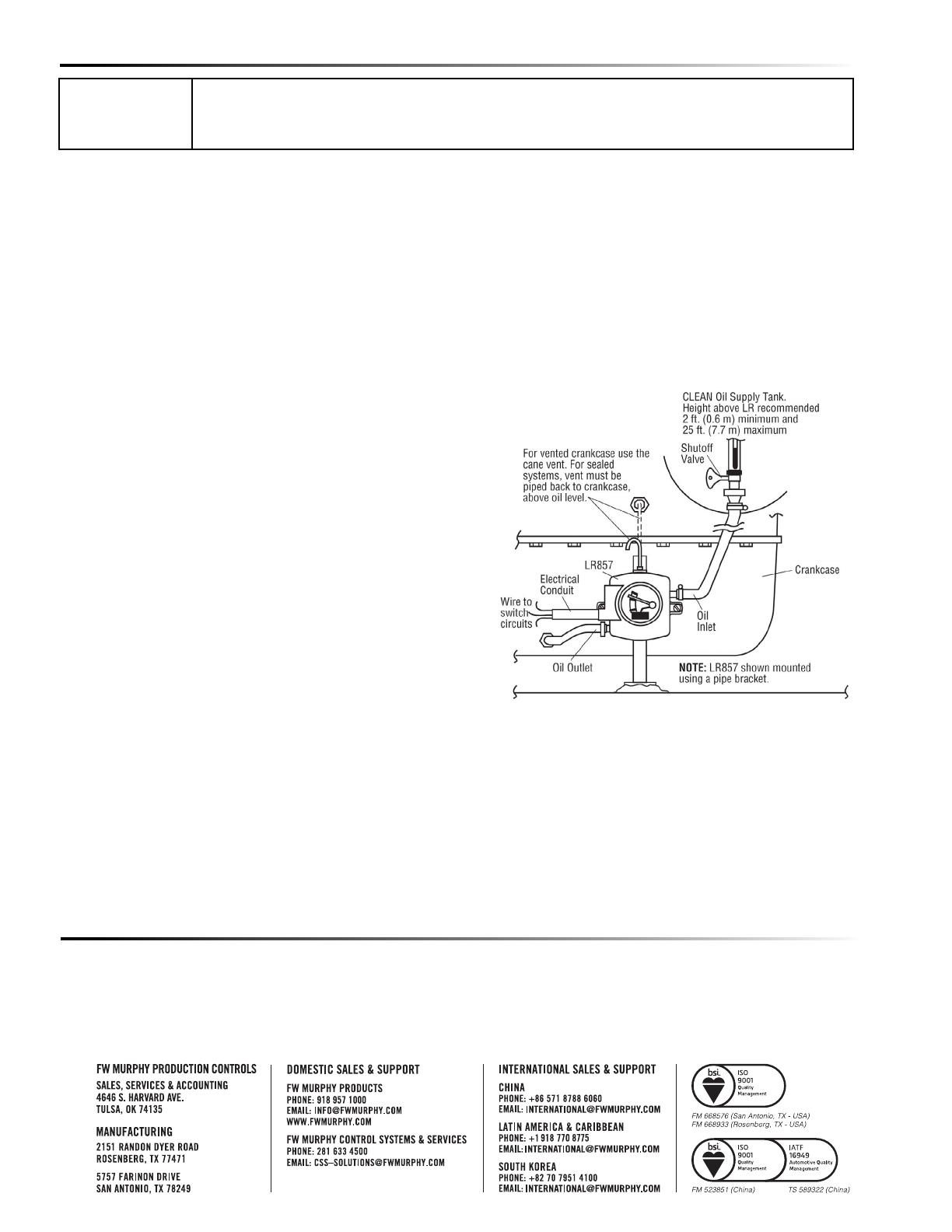
4. Install the crankcase vent connection above the oil level so the tubing is not restricted by any splash, etc.
a. For sealed crankcases, connect a 1/4 in. (6 mm) O.D. tube from the crankcase to the tube tting on the LR857.
b. For vented crankcases, install the copper cane.
c. See drawing for reference.
Warning: Failure to install the tubing or cane vent will result in
improper operation and spillage.
5. Verify that all hose clamps are tight before continuing to the next
step.
6. Rell the crankcase to the proper oil level.
7. Vertically adjust the LR857 so that the pointer is consistent with
the actual running oil level in the crankcase.
8. Check this level against the ADD oil marking on the oil dip stick.
9. To determine the level at which you wish oil to be added, either
drain oil from the crankcase or slightly lower the LR857 mount-
ing so that the pointer/switch actuator will indicate the level at
which oil will be added. This can be estimated by lowering the
LR857 an amount equal to the difference between the FULL and
ADD marks on the dip stick.
10. Tighten the mounting bracket securely after the nal adjustments
are made.
11. Connect a hose between the oil inlet of the LR857 and the oil supply tank. The hose must maintain a downward slope and
not have low spots or droops. A minimum height of 2 ft. (0.6m) above the LR857 is recommended. Maximum head is 25 ft.
(7.7 meters) or 10 psi (6.9 kPa) [0.69 bar].
a. Attach a shutoff valve in the bottom of the supply tank (recommended).
b. Install a lter screen between the supply and the LR857 (recommended).
12. Before lling the supply tank with oil be sure it is clean and dry and the shutoff valve is closed. Also, be sure all hoses and
clamps are tight. Fill the tank with clean oil.
13. After oil tank is full, open the shutoff valve.
Warning: Overll condition can be caused by excessive inlet pressure and/or improper vent-to-crankcase installation.
14. Make the proper electrical connections for the application. See contact ratings on reverse side of the LR857.
Important
Connection of the LR857 must be made to the equipment crankcase at the lowest possible point-
usually the oil drain plug. Hoses, hose clamps and supply tank are supplied by the customer.
These instructions use the FW Murphy mounting and tting kits described in Optional Mounting Parts
section. If you did not order a kit, gather the proper ttings as specied.
Typical Installation
Specification
Inlet Connection: 5/8. (16 mm) I.D. hose
Outlet Connection: 3/8 NPT
Conduit Connection: 1/2 NPT
Case: Die cast aluminum
Lens: Polycarbonate
Float: Brass
Snap-switch: SPDT rating 10 A @ 125 VAC;
0.5 A @ 125 VDC;
10A @ 30 VDC
In order to consistently bring you the highest quality, full-featured products, we reserve the right to change our specifications and designs at any time. FW Murphy product names and the FW
Murphy logo are proprietary trademarks. This document, including textual matter and illustrations, is copyright protected with rights reserved. (c) 2022 FW Murphy. A copy of our typical warranty may
be viewed or printed by going to www.fwmurphy.com/warranty.
  • Page 1 1
  • Page 2 2

FW Murphy LR857 Operating instructions

Type
Operating instructions

FW Murphy LR857 is an automatic lube level regulator designed to maintain the oil level in engines, pumps, and compressors. It features an integral low-level switch for alarms or equipment shutdown in case of oil loss. The LR857 can be mounted vertically or horizontally using optional mounting kits. It has a flow rate of oil with 0.9 specific gravity at 70° F (21° C) and a maximum head of 25 ft. (7.7 meters) or 10 psi (6.9 kPa) [0.69 bar]. The LR857's inlet connection is 5/8 in. (16 mm) I.D. hose, the outlet connection is 3/8 NPT, and the conduit connection is 1/2 NPT.

Ask a question and I''ll find the answer in the document

Finding information in a document is now easier with AI