WM-E2S® modem – Quick Reference Guide
for Itron® ACE6000, ACE8000, SL7000 electricity meters
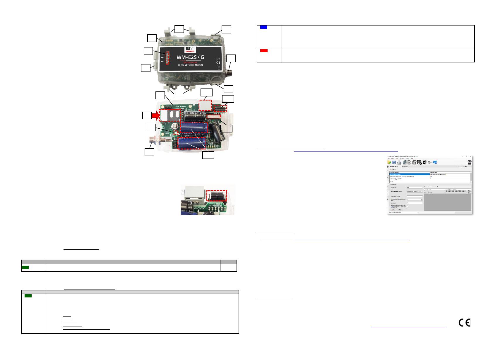
CONNECTION
1 – Plastic enclosure and its top cover
2 – PCB (mainboard)
3 – Fastener points (fixation lags)
4 – Cover holder ear (loose to open the top cover)
5 – FME antenna connector (50 Ohm) – optionally: SMA antenna connector
6 – Status LEDs: from top-to-bottom: LED3 (green), LED1 (blue), LED2 (red)
7 – Cover hinge
8 – Mini SIM-card holder (pull it to right and open up)
9 – Internal antenna connector (U.FL - FME)
10 – RJ45 connector (data connection and DC power supply)
11 – Jumper crossboard (for RS232/RS485 mode selection with jumpers)
12 – Super-capacitors
13 – External connector
POWER SUPPLY AND ENVIRONMENTAL CONDITIONS
▪ Power supply: 8-12V DC (10V DC nominal), Current: 120mA (Itron® ACE 6000),
200mA (Itron® SL7000), Consumption: max. 2W @ 10V DC
▪ Power input: can be supplied by the meter, through the RJ45 connector
▪ Wireless communication: according to the selected module (order options)
▪ Ports: RJ45 connection: RS232 (300/1200/2400/4800/9600 baud) / RS485
▪ Operation temperature: -30°C* to +60°C, rel. 0-95% rel. humidity (*TLS: from -
25°C) / Storage temperature: from -30°C to +85°C, rel. 0-95% rel. humidity
*in case of TLS: -20°C
MECHANICAL DATA / DESIGN
▪ Dimensions: 108 x 88 x 30mm, Weight: 73 gr
▪ Outfit: The modem has a transparent, IP21 protected, antistatic, non-
conductive plastic housing. The enclosure can be fastened by the fixing ears
under the meter’s terminal cover.
▪ Optional DIN-rail fixation can be ordered (the fastener adapter unit is
assembled to the back side of the enclosure by screws) therefore can be used
as an external modem.
INSTALLATION STEPS
▪ Step #1: Remove the meter terminal cover by its screws (with a screwdriver).
▪ Step #2: Ensure that the modem is NOT under power supply, remove the
RJ45 connection from the meter. (The power source will be removed.)
▪ Step #3: Push the white ears of the enclosure’s sides (4), and open up the top cover (1) at the antenna connector. The PCB will be free to touch.
▪ Step #4: Now the PCB will be positioned to left as it can be seen on the photo. Push the plastic SIM holder’s cover (8) from left to right direction,
and open it up.
▪ Step #5: Insert an active SIM card into the holder (8). Take care to the right position (the chip looks down, the card’s cutted edge looks outside
to the antenna. Push the SIM into the guiding rail, close the SIM holder, and push it back (8) from right to left direction, and close back.
▪ Step #6: Ensure that the antenna’s internal black cable is connected onto the U.FL connector (9)!
▪ Step #7: Close back the enclosure’s top cover (1) by the fastener ears (4). You will hear a click sound.
▪ Step #8: Mount an antenna to the FME antenna connector (5). (If you’re using an SMA antenna, then
use SMA-FME converter).
▪ Step #9: Connect the modem to the computer by the RJ45 cable and the RJ45-USB converter, and
set up the jumper’s position into RS232 mode. (the modem can be configured only in RS232 mode
through cable!)
▪ Step #10: Configure the modem by the WM-E Term® software.
▪ Step #11: After the configuration set up the jumpers (11) again, close the required jumper pairs (hints
can be found on the jumper crossboard) - RS232 mode: the internal jumpers are closed / RS485 mode:
the winger pins are closed by the jumpers.
▪ Step #12: Connect the RJ45 cable back to the meter. (If the modem will be used through RS485 port, then you have to modify the jumpers to
RS485 mode!)
▪ Step #13: The modem→Itron® meter connection can be initiated via RS232 or RS485 port. Therefore connect the grey RJ45 cable (14) to the
RJ45 port (10).
▪ Step #14: The RJ45 cable’s other side should be connected to the meter’s RJ45 connector according to the meter type, and the readout port
(RS232 or RS485). The modem will be powered by the meter immediately and it’s operation will be started – which can be checked with LEDs.
OPERATION LED SIGNALS - IN CASE OF CHARGING
Attention! The modem must be charged before the first use – or if it was not been powered for of long time. The charge takes about ~2 minutes if
the supercapacitor was exhausted / discharged.
Over the factory defaults, the operation and the sequence of the LED signals can be changed by the WM-E Term® configuration tool, at the General
Meter Settings parameter group. The free to choose further LED options can be found in the WM-E2S® modem’s Installation Manual.
OPERATION LED SIGNALS – IN CASE OF NORMAL OPERATION
LED3
SIM status /
SIM failure or
PIN code
failure
• Continuously lighting, until the device is not on the cellular network and RSSI cannot be detected (SIM is okay)
• When the SIM PIN is okay: led is active
• If there is no SIM detected or SIM PIN is wrong: blinking once per second (slow flashing)
• The RSSI (signal strength) value is signed also by this LED. Flashing by “N”-times in every 10-15 seconds, depending on the RSSI
refresh period. The RSSI value can be 1,2,3 or 4 on current cellular network. The numbers of RSSI flashings are different on every
network technology, according to the following:
o on 2G: 1 flashing: RSSI >= -98 / 2 flashings: RSSI between -97 and -91 / 3 flashings: RSSI -90 to -65 / 4 flashings: RSSI > -64
o on 3G: 1 flashing: RSSI >= -103 / 2 flashings: RSSI between -102 and -92 / 3 flashings: RSSI -91 to -65 / 4 flashings: RSSI > -64
o on 4G LTE: 1 flashing: RSSI >= -122 / 2 flashings: RSSI between -121 to -107 / 3 flashings: RSSI -106 to -85 / 4 flashings: RSSI > -84
o on LTE Cat.M1: 1 flashing: RSSI >= -126 / 2 flashings: RSSI between -125 and -116 / 3 flashings: RSSI -115 to -85 / 4 flashings: RSSI > -84
o on LTE Cat. NB-IoT (Narrow Band): 1 flashing: RSSI >= -122 / 2 flashings: RSSI -121 to -107 / 3 flashings: RSSI between -106 and -85 /
4 flashings: RSSI > -84
• During network registration: led is active
• During network searching: blinking once per second
• When connected to the network and the IP connection is okay: blinking twice per second
• When the mobile network access technology was changed: quick flashing will be relied: 2G → 2 flashing per second / 3G
→3 flashing per second / 4G → 4 flashing per second
• If there is no available cellular network detected: the led will be blank
• During the CSD call and IP data forwarding, the LED is ligthing continuously
• By general: the led is inactive
• During communiaction: the led is active (flashing)
Note, that during the firmware uploading the LEDs are operating as it is normal – there is no significal LED signal for the FW refresh progress. After
the Firmware installation, the 3 LEDs will be lighting for 5 seconds and all will blank, then the modem restarting by the new firmware. Then all LED
signals will be operating as it was listed above.
CONFIGURATION OF THE MODEM
The modem can be configured with the WM-E Term® software by setup of its parameters. This must be done before the operation and usage.
▪ During the configuration process, the RJ45 (5) connector must be removed from the meter connector and should be connected to the PC. During
the PC connection the meter data cannot be received by the modem.
▪ Connect the modem to the computer by the RJ45 cable and the RJ45-USB converter. The jumpers must be in RS232 position!
Important! During the configuration, the power supply of the modem is assured by this converter board, on USB connection. Some
computers can sensitive for USB current changes. In this case you should use an external power supply with special connection.
▪ After the configuration reconnect the RJ45 cable to the meter!
▪ For the serial cable connection configure COM port settings of the connected computer according to the modem serial port properties in the
Windows at the a Start menu / Control panel / Device Manager / Ports (COM and LTP) at the Properties: Bit/sec: 9600, Data bits: 8, Parity:
None, Stopbits: 1, Bandwith control: No
▪ The configuration can be performed via CSData call or TCP connection if the APN is already configured.
MODEM CONFIGURATION BY THE WM-E TERM®
The Microsoft .NET framework runtime environment is required on your computer. For modem configuration and testing you will need an APN/data
package enabled, an active SIM-card.
The configuration is possible without a SIM card, but in this case the modem is performing restart periodically, and some modem features will be
not available until the SIM card is inserted (e.g. remote access).
Connection to the modem (via RS232 port*)
▪ Step #1: Download the https://www.m2mserver.com/m2m-downloads/WM-ETerm_v1_3_63.zip file. Uncompress and start the wm-eterm.exe file.
▪ Step #2: Push the Login button and choose the WM-E2S device by it’s Select
button.
▪ Step #3: At left on the screen, at the Connection type tab, choose the Serial tab,
and fill the New connection field (new connection profile name) and push the
Create button.
▪ Step #4: Choose the proper COM port and configure the Data transmission
speed to 9600 baud (in Windows® you have to configure the same speed). The
Data format value should be 8,N,1. Push the Save button to make the connection
profile.
▪ Step #5: At the bottom left side of the screen choose a connection type (serial).
▪ Step #6: Choose the Device information icon from the menu and check the RSSI
value, that the signal strength is enough and the antenna position is right or not.
(The indicator should be at least yellow (average signal) or green (good signal
quality). If you have weak values, change the antenna position while you will not
receive better dBm value. (you have to request the status again by the icon).
▪ Step #7: Choose the Parameter readout icon for the modem connection. The
modem will be connected and its parameter values, identifiers will be read out.
*If you are using data call (CSD) or TCP/IP connection remotely with the modem– check the Installation manual for connection parameters!
Parameter configuration
▪ Step #1: Download a WM-E Term sample configuration file, according to the Itron meter type. Choose the File / Load menu to load the file.
▪ RS232 or RS485 mode: https://m2mserver.com/m2m-downloads/WM-E2S-STD-DEFAULT-CONFIG.zip
▪ Step #2: At the Parameter group choose the APN group, then push to the Edit values button. Define the APN server and in case of neccassary
the APN Username and APN password fields, and push to the OK button.
▪ Step #3: Choose M2M parameter group, then push Edit values button. Add PORT number to the Transparent (IEC) meter readout port field –
which will be used for the remote meter readout. Give the configuration PORT NUMBER to the Configuration and firmware download port.
▪ Step #4: If the SIM is using a SIM PIN, then you have to define it to the Mobile network parameter group, and give it into the SIM PIN field. Here
you can choose the Mobile technology (e.g. All available network technology - which is recommended to select) or choose the LTE to 2G
(fallback) for network connection. You can also select a mobile operator and network– as automatic or manual. Then push to the OK button.
▪ Step #5: The RS232 serial port and transparent settings can be found in the Trans. / NTA parameter group. The default settings are the following:
at Multi utility mode: transzparent mode, Meter port baud rate: 9600, Data format: Fixed 8N1). Then push to the OK button.
▪ Step #6: The RS485 settings can be performed in the RS485 meter interface parameter group. The RS485 mode can be setup here. If you are
using RS232 port then you have to disable this option at the settings! Then push to the OK button.
▪ Step #7: After the settings you have to choose the Parameter write icon to send the settings to the modem. You can see the progress of the
upload at the bottom status’s progress bar. At the end of the progress the modem will be restarted and will be starting with the new settings.
▪ Step #8: If you want to use the modem on RS485 port for meter readout, therefore after the configuration, modify the jumpers to RS485 mode!
Further setting options
▪ The modem handling can be refined at the Watchdog parameter group.
▪ The configured parameters should be save to your computer also by the File/Save menu.
▪ Firmware upgrade: select the Devices menu, and the Single Firmware upload item (where you can upload the proper.DWL extension file). After
the progress of the upload, the modem will be rebooting and operating with the new firmware and the previous setttings!
SUPPORT
The product has CE sign according to the European regulations.
The product documentation, software can be found on the product’s website: https://www.m2mserver.com/en/product/wm-e2s/
At first statup, during the charging of the exhausted supercapacitors, only green LED will flashing quickly. Only this LED is active
during the charge. Wait until the device will be fully charged.


