Dell Latitude 7410 Chromebook Enterprise Owner's manual
- Type
- Owner's manual

Dell Latitude 7410 Chromebook Enterprise
Service Manual
1
Regulatory Model: P119G / P131G
Regulatory Type: P119G002 / P131G002
August 2020
Rev. A00

Notes, cautions, and warnings
NOTE: A NOTE indicates important information that helps you make better use of your product.
CAUTION: A CAUTION indicates either potential damage to hardware or loss of data and tells you how to avoid
the problem.
WARNING: A WARNING indicates a potential for property damage, personal injury, or death.
© 2020 Dell Inc. or its subsidiaries. All rights reserved. Dell, EMC, and other trademarks are trademarks of Dell Inc. or its subsidiaries. Other
trademarks may be trademarks of their respective owners.

Notes, cautions, and warnings
NOTE: A NOTE indicates important information that helps you make better use of your product.
CAUTION: A CAUTION indicates either potential damage to hardware or loss of data and tells you how to avoid
the problem.
WARNING: A WARNING indicates a potential for property damage, personal injury, or death.
© 2020 Dell Inc. or its subsidiaries. All rights reserved. Dell, EMC, and other trademarks are trademarks of Dell Inc. or its subsidiaries.
Other trademarks may be trademarks of their respective owners.

Chapter 1: Working on your computer........................................................................................... 6
Safety instructions.............................................................................................................................................................. 6
Working inside your computer.................................................................................................................................... 6
After working inside your computer..........................................................................................................................8
Chapter 2: Technology and components........................................................................................ 9
Display and Stylus Behaviour............................................................................................................................................ 9
Touch Screen Behavior................................................................................................................................................ 9
Stylus Behavior...............................................................................................................................................................9
Keyboard shortcuts........................................................................................................................................................... 10
USB Type-C........................................................................................................................................................................ 15
USB features.......................................................................................................................................................................15
Chapter 3: Major components of your system.............................................................................. 18
Major components of your system................................................................................................................................ 18
Chapter 4: Disassembly and reassembly ..................................................................................... 20
MicroSD card..................................................................................................................................................................... 20
Removing the microSD card..................................................................................................................................... 20
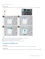
Installing the microSD card....................................................................................................................................... 22
Base cover.......................................................................................................................................................................... 22
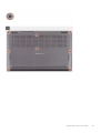
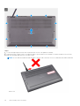
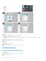
Removing the base cover.......................................................................................................................................... 22
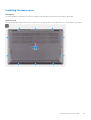
Installing the base cover............................................................................................................................................ 25
Battery................................................................................................................................................................................. 26
Lithium-ion battery precautions...............................................................................................................................26
Disconnecting the battery cable.............................................................................................................................. 27
Reconnecting the battery cable...............................................................................................................................27
Removing the battery.................................................................................................................................................28
Installing the battery...................................................................................................................................................29
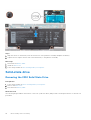
Solid-state drive................................................................................................................................................................ 30
Removing the 2230 Solid State Drive.................................................................................................................... 30
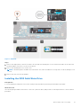
Installing the 2230 Solid State Drive....................................................................................................................... 31
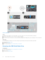
Removing the 2280 Solid State Drive.................................................................................................................... 32
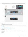
Installing the 2280 Solid State Drive...................................................................................................................... 33
WWAN card........................................................................................................................................................................ 34
Removing the WWAN card....................................................................................................................................... 34
Installing the WWAN card......................................................................................................................................... 35
Palmrest antenna.............................................................................................................................................................. 36
Disconnecting the WLAN antenna.......................................................................................................................... 36
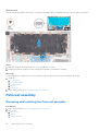
Heatsink assembly............................................................................................................................................................. 37
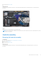
Removing the heatsink assembly.............................................................................................................................37
Installing the heatsink assembly...............................................................................................................................38
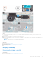
Display assembly................................................................................................................................................................39
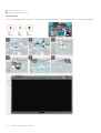
Removing the display assembly............................................................................................................................... 39
Contents
4 Contents

Installing the display assembly.................................................................................................................................. 41
Speakers.............................................................................................................................................................................. 43
Removing the speaker................................................................................................................................................43
Installing the speaker.................................................................................................................................................. 44
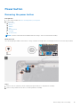
Power button..................................................................................................................................................................... 45
Removing the power button.....................................................................................................................................45
Installing the power button....................................................................................................................................... 46
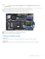
System board......................................................................................................................................................................47
Removing the system board..................................................................................................................................... 47
Installing the system board....................................................................................................................................... 49
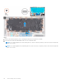
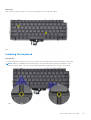
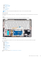
Keyboard.............................................................................................................................................................................. 51
Removing the keyboard..............................................................................................................................................51
Installing the keyboard............................................................................................................................................... 53
Palmrest assembly............................................................................................................................................................ 54
Removing and Installing the Palmrest assembly.................................................................................................. 54
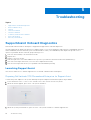
Chapter 5: Troubleshooting.........................................................................................................56
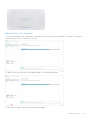
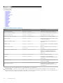
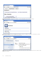
SupportAssist Onboard Diagnostics ............................................................................................................................56
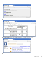
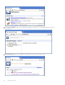
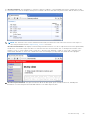
Launching SupportAssist...........................................................................................................................................56
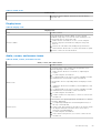
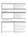
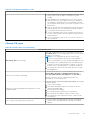
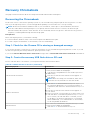
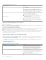
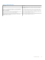
Basic troubleshooting.......................................................................................................................................................58
Power issues.................................................................................................................................................................58
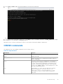
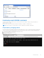
CROSH.................................................................................................................................................................................62
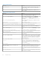
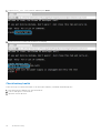
CROSH commands........................................................................................................................................................... 63
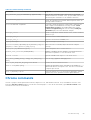
Chrome commands........................................................................................................................................................... 65
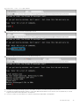
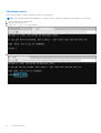
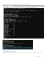
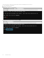
Commonly used CROSH command................................................................................................................................71
Check battery charging status..................................................................................................................................71
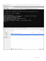
Reset Chromebook............................................................................................................................................................78
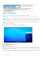
Recovery Chromebook.....................................................................................................................................................79
Recovering the Chromebook.................................................................................................................................... 79
Chapter 6: Getting help...............................................................................................................82
Contacting Dell.................................................................................................................................................................. 82
Contents
5

Working on your computer
Topics:
• Safety instructions
Safety instructions
Use the following safety guidelines to protect your computer from potential damage and to ensure your personal safety. Unless
otherwise noted, each procedure included in this document assumes that you have read the safety information that shipped
with your computer.
WARNING: Before working inside your computer, read the safety information that is shipped with your
computer. For more safety best practices, see the Regulatory Compliance home page at www.dell.com/
regulatory_compliance.
WARNING: Disconnect your computer from all power sources before opening the computer cover or panels.
After you finish working inside the computer, replace all covers, panels, and screws before connecting your
computer to an electrical outlet.
CAUTION: To avoid damaging the computer, ensure that the work surface is flat, dry, and clean.
CAUTION: To avoid damaging the components and cards, handle them by their edges, and avoid touching the
pins and the contacts.
CAUTION: You should only perform troubleshooting and repairs as authorized or directed by the Dell technical
assistance team. Damage due to servicing that is not authorized by Dell is not covered by your warranty. See the
safety instructions that is shipped with the product or at www.dell.com/regulatory_compliance.
CAUTION: Before touching anything inside your computer, ground yourself by touching an unpainted metal
surface, such as the metal at the back of the computer. While you work, periodically touch an unpainted metal
surface to dissipate static electricity which could harm internal components.
CAUTION: When you disconnect a cable, pull it by its connector or its pull tab, not the cable itself. Some cables
have connectors with locking tabs or thumbscrews that you must disengage before disconnecting the cable.
When disconnecting cables, keep them evenly aligned to avoid bending the connector pins. When connecting
cables, ensure that the ports and the connectors are correctly oriented and aligned.
CAUTION: Press and eject any installed card from the media-card reader.
NOTE: The color of your computer and certain components may appear differently than shown in this document.
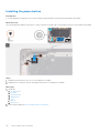
Working inside your computer
Before working inside your computer
About this task
NOTE: The images in this document may differ from your computer depending on the configuration you ordered.
1
6 Working on your computer

Steps
1. Save and close all open files and exit all open applications.
2. Shut down your computer. Click Start > Power > Shut down.
NOTE: If you are using a different operating system, see the documentation of your operating system for shut-down
instructions.
3. Disconnect your computer and all attached devices from their electrical outlets.
4. Disconnect all attached network devices and peripherals, such as keyboard, mouse, and monitor from your computer.
CAUTION: To disconnect a network cable, first unplug the cable from your computer and then unplug the
cable from the network device.
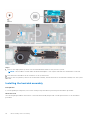
5. Remove any media card and optical disc from your computer, if applicable.
Electrostatic discharge—ESD protection
ESD is a major concern when you handle electronic components, especially sensitive components such as expansion cards,
processors, memory DIMMs, and system boards. Very slight charges can damage circuits in ways that may not be obvious, such
as intermittent problems or a shortened product life span. As the industry pushes for lower power requirements and increased
density, ESD protection is an increasing concern.
Due to the increased density of semiconductors used in recent Dell products, the sensitivity to static damage is now higher than
in previous Dell products. For this reason, some previously approved methods of handling parts are no longer applicable.
Two recognized types of ESD damage are catastrophic and intermittent failures.
● Catastrophic – Catastrophic failures represent approximately 20 percent of ESD-related failures. The damage causes
an immediate and complete loss of device functionality. An example of catastrophic failure is a memory DIMM that has
received a static shock and immediately generates a "No POST/No Video" symptom with a beep code emitted for missing or
nonfunctional memory.
● Intermittent – Intermittent failures represent approximately 80 percent of ESD-related failures. The high rate of
intermittent failures means that most of the time when damage occurs, it is not immediately recognizable. The DIMM
receives a static shock, but the tracing is merely weakened and does not immediately produce outward symptoms related to
the damage. The weakened trace may take weeks or months to melt, and in the meantime may cause degradation of memory
integrity, intermittent memory errors, etc.
The more difficult type of damage to recognize and troubleshoot is the intermittent (also called latent or "walking wounded")
failure.
Perform the following steps to prevent ESD damage:
● Use a wired ESD wrist strap that is properly grounded. The use of wireless anti-static straps is no longer allowed; they do not
provide adequate protection. Touching the chassis before handling parts does not ensure adequate ESD protection on parts
with increased sensitivity to ESD damage.
● Handle all static-sensitive components in a static-safe area. If possible, use anti-static floor pads and workbench pads.
● When unpacking a static-sensitive component from its shipping carton, do not remove the component from the anti-static
packing material until you are ready to install the component. Before unwrapping the anti-static packaging, ensure that you
discharge static electricity from your body.
● Before transporting a static-sensitive component, place it in an anti-static container or packaging.
ESD field service kit
The unmonitored Field Service kit is the most commonly used service kit. Each Field Service kit includes three main components:
anti-static mat, wrist strap, and bonding wire.
Components of an ESD field service kit
The components of an ESD field service kit are:
● Anti-Static Mat – The anti-static mat is dissipative and parts can be placed on it during service procedures. When using an
anti-static mat, your wrist strap should be snug and the bonding wire should be connected to the mat and to any bare metal
on the system being worked on. Once deployed properly, service parts can be removed from the ESD bag and placed directly
on the mat. ESD-sensitive items are safe in your hand, on the ESD mat, in the system, or inside a bag.
Working on your computer
7

● Wrist Strap and Bonding Wire – The wrist strap and bonding wire can be either directly connected between your wrist
and bare metal on the hardware if the ESD mat is not required, or connected to the anti-static mat to protect hardware that
is temporarily placed on the mat. The physical connection of the wrist strap and bonding wire between your skin, the ESD
mat, and the hardware is known as bonding. Use only Field Service kits with a wrist strap, mat, and bonding wire. Never
use wireless wrist straps. Always be aware that the internal wires of a wrist strap are prone to damage from normal wear
and tear, and must be checked regularly with a wrist strap tester in order to avoid accidental ESD hardware damage. It is
recommended to test the wrist strap and bonding wire at least once per week.
● ESD Wrist Strap Tester – The wires inside of an ESD strap are prone to damage over time. When using an unmonitored
kit, it is a best practice to regularly test the strap prior to each service call, and at a minimum, test once per week. A
wrist strap tester is the best method for doing this test. If you do not have your own wrist strap tester, check with your
regional office to find out if they have one. To perform the test, plug the wrist-strap's bonding-wire into the tester while it is
strapped to your wrist and push the button to test. A green LED is lit if the test is successful; a red LED is lit and an alarm
sounds if the test fails.
● Insulator Elements – It is critical to keep ESD sensitive devices, such as plastic heat sink casings, away from internal parts
that are insulators and often highly charged.
● Working Environment – Before deploying the ESD Field Service kit, assess the situation at the customer location. For
example, deploying the kit for a server environment is different than for a desktop or portable environment. Servers are
typically installed in a rack within a data center; desktops or portables are typically placed on office desks or cubicles. Always
look for a large open flat work area that is free of clutter and large enough to deploy the ESD kit with additional space to
accommodate the type of system that is being repaired. The workspace should also be free of insulators that can cause an
ESD event. On the work area, insulators such as Styrofoam and other plastics should always be moved at least 12 inches or
30 centimeters away from sensitive parts before physically handling any hardware components
● ESD Packaging – All ESD-sensitive devices must be shipped and received in static-safe packaging. Metal, static-shielded
bags are preferred. However, you should always return the damaged part using the same ESD bag and packaging that the
new part arrived in. The ESD bag should be folded over and taped shut and all the same foam packing material should be
used in the original box that the new part arrived in. ESD-sensitive devices should be removed from packaging only at an
ESD-protected work surface, and parts should never be placed on top of the ESD bag because only the inside of the bag is
shielded. Always place parts in your hand, on the ESD mat, in the system, or inside an anti-static bag.
● Transporting Sensitive Components – When transporting ESD sensitive components such as replacement parts or parts
to be returned to Dell, it is critical to place these parts in anti-static bags for safe transport.
ESD protection summary
It is recommended that all field service technicians use the traditional wired ESD grounding wrist strap and protective anti-static
mat at all times when servicing Dell products. In addition, it is critical that technicians keep sensitive parts separate from all
insulator parts while performing service and that they use anti-static bags for transporting sensitive components.
After working inside your computer
About this task
CAUTION: Leaving stray or loose screws inside your computer may severely damage your computer.
Steps
1. Replace all screws and ensure that no stray screws remain inside your computer.
2. Connect any external devices, peripherals, or cables you removed before working on your computer.
3. Replace any media cards, discs, or any other parts that you removed before working on your computer.
4. Connect your computer and all attached devices to their electrical outlets.
5. Turn on your computer.
8
Working on your computer

Technology and components
This chapter details the technology and components available in the system.
Topics:
• Display and Stylus Behaviour
• Keyboard shortcuts
• USB Type-C
• USB features
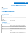
Display and Stylus Behaviour
Touch Screen Behavior
Table 1. Touch Screen Behavior
User Action Description
Long swipe up from the bottom Go to your Home Screen
Short swipe up from the bottom Show your pinned apps
Swipe up from the bottom and hold View all open app windows
From overview, hold and drag a window
to one side
Split your screen
Swipe from the left side Go back to previous screen
Stylus Behavior
Table 2. Stylus Behavior (continued)
User Action Description
Positioning To position the screen cursor, move the Pen slightly above the Dell screen without
touching the screen surface. To make a selection, press the Pen tip on the display
screen.
Clicking Tap the display screen once with the Pen tip, or touch the Pen to the screen with
enough pressure to register a click.
Dragging Select an object, then slide the Pen tip across the screen to move the object.
Erasing Press and hold the bottom barrel button and move the tip over the area you want
to erase.
Context Menu / Right click Press and hold the top barrel button to open the context menu or perform a
right-click.
New note Double-click the top button to launch "New Note"
Working with pressure sensitivity To draw, ink, or write with pressure sensitivity, move the Pen along the display
screen surface while applying various amounts of pressure downward on the tip of
2
Technology and components 9

Table 2. Stylus Behavior
User Action Description
the Pen. Press hard for thick lines or dense color. Press gently for thin lines or
softer color.
Drawing with Tilt Tilt can be used to control line shape and thickness in any application that supports
this feature.
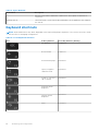
Keyboard shortcuts
NOTE: Keyboard characters may differ depending on the keyboard language configuration. Keys used for shortcuts remain
the same across all language configurations.
Table 3. List of keyboard shortcuts
Keys Primary behavior Secondary behavior (Fn+Key)
Esc behavior Esc behavior
Browser Back
F1 behavior
Reload current page
F2 behavior
Open your page in
fullscreen mode
F3 behavior
Switch to your next
tab or window
F4 behavior
Decrease screen
brightness
F5 behavior
Increase screen
brightness
F6 behavior
Mute
F7 behavior
10 Technology and components

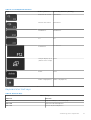
Table 3. List of keyboard shortcuts
Keys Primary behavior Secondary behavior (Fn+Key)
Decrease the volume
F8 behavior
Increase the volume
F9 behavior
F10 behavior
F10 behavior
F11 F11
F12 behavior
F12 behavior
Changes display layout
(multi monitors setup)
None
Delete None
Globe/ Language Key Globe/ Language Key
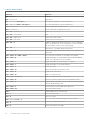
Keyboard shortcut keys
Table 4. Shortcut keys
Shortcut keys
Shortcut Function
Esc Stop the loading of your current page
Ctrl + F5 Decrease keyboard brightness
Ctrl + F6 Increase keyboard brightness
Technology and components 11

Table 4. Shortcut keys
Shortcut keys
Shortcut Function
Alt + Up arrow Page up
Alt + Down arrow Page down
Alt + Left arrow (Backspace) Go to previous page in your browsing history
Alt + Right arrow(Shift + Backspace) Go to the next page in your browsing history
Ctrl + Right arrow Move to the end of the next word
Ctrl + Down arrow Move to the start of the previous word
Ctrl + Alt + Up arrow Home
Ctrl + Alt + Down arrow End
Ctrl + Alt + Right arrow Select next word or letter
Ctrl + Alt + Left arrow Select previous word or letter
Ctrl + Alt + Z Enable or disable accessibility features if you're not signed in
with a Google Account. If you're signed in, you can configure
the accessibility feature on the Settings page.
Ctrl + Alt + /
Open the list of available keyboard shortcuts
Ctrl + Shift + D Save all open pages in the current window as bookmarks in a
new folder
Ctrl + Shift + G orShift + Enter Go to the previous match for the input in the find bar
Ctrl + Shift + B Toggle the display of the bookmarks bar. Bookmarks appear
on the New Tab page if the bar is hidden.
Ctrl + Shift + I Toggle the display of the Developer Tools panel
Ctrl + Shift + J Toggle the display of the DOM Inspector
Ctrl + Shift + L Locks the screen
Ctrl + Shift + N Open a new window in incognito mode
Ctrl + Shift + B Toggle the bookmark bar
Ctrl + Shift + Q Sign out Google Account
Ctrl + Shift + Q (twice) Sign out Google Account on Chrome OS
Ctrl + Shift + R Reload your current page without using cached content
Ctrl + Shift + T Reopen the last tab being closed. Google Chrome remembers
the last 10 tabs being closed.
Ctrl + Shift + V Paste content from the clipboard as plain text
Ctrl + Shift + W Close the current window
Ctrl + . Display hidden files in the Files app
Ctrl + ? Go to the Help Center
Ctrl + 0 Reset zoom level
Ctrl + 1 through Ctrl + 8
Go to the tab at the specified position in the window
Ctrl + 9
Go to the last tab in the window
Ctrl + A Select everything on the page
12 Technology and components

Table 4. Shortcut keys
Shortcut keys
Shortcut Function
Ctrl + C Copy selected content to the clipboard
Ctrl + D Save your current webpage as a bookmark
Ctrl + F Search your current webpage
Ctrl + G or Enter Go to the next match for the input in the find bar
Ctrl + H Open the History page
Ctrl + J Open the Downloads page
Ctrl + K or Ctrl + E Perform a search. Type a search term after the question mark
in the address bar and press Enter.
Ctrl + L or Alt + D
Select the content in the address bar
Ctrl + N Open a new window
Ctrl + O Open a file in the browser
Ctrl + P Print your current page
Ctrl + R Reload your current page
Ctrl + S Save your current page
Ctrl + T Open a new tab
Ctrl + U View page source
Ctrl + V Paste content from the clipboard
Ctrl + W Close the current tab
Ctrl + X Cut
Ctrl + Z Undo the last action
Ctrl + Backspace Delete the previous word
Ctrl + Tab Switch to next tab
Ctrl + Enter Add www. and .com to your input in the address bar and open
the resulting URL
Ctrl + Shift + Tab Go to the previous tab in the window
Ctrl + Shift + Refresh Rotate screen 90 degrees
Ctrl + Shift + ) Reset screen scale
Ctrl + Shift + + Increase screen scale
Ctrl + Shift + - Decrease screen scale
Ctrl + Shift + Refresh Rotate screen 90 degrees
Ctrl + + Zoom in on the page
Ctrl + - Zoom out on the page
Alt + click a link Open the link you clicked in a new background tab
Alt + 1 through Alt + 8 Go to the window at the specified position
Alt + 9 Go to the last window open
Alt + E or Alt + F
Open the Chrome menu on the browser toolbar
Alt + Backspace Delete the next letter (forward delete)
Technology and components 13

Table 4. Shortcut keys
Shortcut keys
Shortcut Function
Alt + Tab Go to the next window that have opened
Alt + Shift + Tab Go to the previous window that have opened
Alt + Shift + M Open the Files app
Alt + Shift + B Place focus on the bookmarks bar. Use the actions listed for
Shift+Alt+T to move the focus.
Shift + Alt + S Opens the status area in the bottom-right corner of the
screen
Shift + Alt + L
Place focus on the launcher
● Press Tab or the right arrow to focus on the next item in
the toolbar
● Press Shift+Tab or the left arrow to focus on the previous
item in the toolbar
● Press Space or Enter to activate buttons, including page
actions and browser actions
● Press Shift + Volume increase to open the context menu
for the button (if available)
● Press Esc to return focus to the page
Shift + Search + Volume Up Open right-click menus for focused items
Shift + Esc Open the Task Manager
To see more shortcuts, simply press Ctrl+Alt+? To open the keyboard viewer on your screen.
Keyboard Function (Fn) behavior
Table 5. Function (Fn) key (continued)
Key Primary Function Secondary Function
F12 Toggles privacy display ON and
OFF and displays the user mode.
If the system does not support
privacy mode, the function will
be as per the operating system
or application specific F12 default
behavior.
Operating system or application specific F12 default
behavior.
Project mode Toggles between mirrored and
extended display modes.
Null
Delete Delete function Null
Power Button Changes the system power state Null
Language Key Switches between the keyboard
languages that the user has
set. The language key is located
between the Fn and left Alt key.
You can activate the language key
using the Ctrl + Shift + Space
bar keys combination.
NOTE: The language key
functionality will be active
Null
14 Technology and components

Table 5. Function (Fn) key
Key Primary Function Secondary Function
if more than one keyboard
language is set.
To see more shortcuts, simply press Ctrl+Alt+? To open the keyboard viewer on your screen.
USB Type-C
USB Type-C is a new, tiny physical connector. The connector itself can support various exciting new USB standards like USB 3.1
and USB power delivery (USB PD).
Alternate Mode
USB Type-C is a new connector standard that is very small. It is about a third the size of an old USB Type-A plug. This is
a single connector standard that every device should be able to use. USB Type-C ports can support a variety of different
protocols using “alternate modes,” which allows you to have adapters that can output HDMI, VGA, DisplayPort, or other types
of connections from that single USB port
USB Power Delivery
The USB PD specification is also closely intertwined with USB Type-C. Currently, smartphones, tablets, and other mobile
devices often use a USB connection to charge. A USB 2.0 connection provides up to 2.5 watts of power — that'll charge your
phone, but that's about it. A laptop might require up to 60 watts, for example. The USB Power Delivery specification ups this
power delivery to 100 watts. It's bi-directional, so a device can either send or receive power. And this power can be transferred
at the same time the device is transmitting data across the connection.
This could spell the end of all those proprietary laptop charging cables, with everything charging via a standard USB connection.
You could charge your laptop from one of those portable battery packs you charge your smartphones and other portable devices
from today. You could plug your laptop into an external display connected to a power cable, and that external display would
charge your laptop as you used it as an external display — all via the one little USB Type-C connection. To use this, the device
and the cable have to support USB Power Delivery. Just having a USB Type-C connection doesn't necessarily mean they do.
USB Type-C and USB 3.1
USB 3.1 is a new USB standard. USB 3's theoretical bandwidth is 5 Gbps, while USB 3.1's is 10 Gbps. That's double the
bandwidth, as fast as a first-generation Thunderbolt connector. USB Type-C isn't the same thing as USB 3.1. USB Type-C is just
a connector shape, and the underlying technology could just be USB 2 or USB 3.0. In fact, Nokia's N1 Android tablet uses a USB
Type-C connector, but underneath it's all USB 2.0 — not even USB 3.0. However, these technologies are closely related.
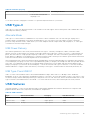
USB features
Universal Serial Bus, or USB, was introduced in 1996. It dramatically simplified the connection between host computers and
peripheral devices like mouses, keyboards, external drivers, and printers.
Table 6. USB evolution
Type Data Transfer Rate Category Introduction Year
USB 2.0 480 Mbps High Speed 2000
USB 3.2 Gen 1 5 Gbps Super-Speed 2010
USB 3.2 Gen 2 10 Gbps Super-Speed 2013
Technology and components 15

USB 3.2 Gen 1 (Super-Speed USB)
For years, the USB 2.0 has been firmly entrenched as the de facto interface standard in the PC world with about 6 billion
devices sold, and yet the need for more speed grows by ever faster computing hardware and ever greater bandwidth demands.
The USB 3.2 Gen 1 finally has the answer to the consumer's demands with a theoretically 10 times faster than its predecessor. In
a nutshell, USB 3.2 Gen 1 features are as follows:
● Higher transfer rates (up to 5 Gbps)
● Increased maximum bus power and increased device current draw to better accommodate power-hungry devices
● New power management features
● Full-duplex data transfers and support for new transfer types
● Backward USB 2.0 compatibility
● New connectors and cable
The topics below cover some of the most commonly asked questions regarding USB 3.2 Gen 1.
Speed
Currently, there are 3 speed modes that are defined by the latest USB 3.2 Gen 1 specification. They are Super-Speed, Hi-Speed,
and Full-Speed. The new Super-Speed mode has a transfer rate of 4.8 Gbps. While the specification retains Hi-Speed, and
Full-Speed USB mode, commonly known as USB 2.0 and 1.1 respectively, the slower modes still operate at 480 Mbps and 12
Mbps respectively and are kept to maintain backward compatibility.
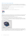
USB 3.2 Gen 1 achieves the much higher performance by the technical changes below:
● An additional physical bus that is added in parallel with the existing USB 2.0 bus (see the figure below).
● USB 2.0 previously had four wires (power, ground, and a pair for differential data); USB 3.2 Gen 1 adds four more for two
pairs of differential signals (receive and transmit) for a combined total of eight connections in the connectors and cabling.
● USB 3.2 Gen 1 utilizes the bi-directional data interface, rather than USB 2.0's half-duplex arrangement. This gives a 10-fold
increase in theoretical bandwidth.
With today's ever increasing demands that are placed on data transfers with high-definition video content, terabyte storage
devices, high megapixel count digital cameras etc., USB 2.0 may not be fast enough. Furthermore, no USB 2.0 connection could
ever come close to the 480Mbps theoretical maximum throughput, making data transfer at around 320 Mbps (40 MB/s) —
the actual real-world maximum. Similarly, USB 3.2 Gen 1 connections will never achieve 4.8Gbps. We will likely see a real-world
maximum rate of 400 MB/s with overheads. At this speed, USB 3.2 Gen 1 is a 10x improvement over USB 2.0.
16
Technology and components

Applications
USB 3.2 Gen 1 opens up the laneways and provides more headroom for devices to deliver a better overall experience. Where
USB video was barely tolerable previously (both from a maximum resolution, latency, and video compression perspective), it's
easy to imagine that with 5-10 times the bandwidth available, USB video solutions should work that much better. Single-link
DVI requires almost 2Gbps throughput. Where 480Mbps was limiting, 5Gbps is more than promising. With its promised 4.8Gbps
speed, the standard will find its way into some products that previously weren't USB territory, like external RAID storage
systems.
Listed below are some of the available Super-Speed USB 3.2 Gen 1 products:
● External Desktop USB 3.2 Gen 1 Hard Drives
● Portable USB 3.2 Gen 1 Hard Drives
● USB 3.2 Gen 1 Drive Docks & Adapters
● USB 3.2 Gen 1 Flash Drives & Readers
● USB 3.2 Gen 1 Solid-state Drives
● USB 3.2 Gen 1 RAIDs
● Optical Media Drives
● Multimedia Devices
● Networking
● USB 3.2 Gen 1 Adapter Cards & Hubs
Compatibility
The good news is that USB 3.2 Gen 1 has been carefully planned from the start to peacefully co-exist with USB 2.0. First of all,
while USB 3.2 Gen 1 specifies new physical connections and thus new cables to take advantage of the higher speed capability
of the new protocol, the connector itself remains the same rectangular shape with the four USB 2.0 contacts in the exact same
location as before. Five new connections to carry receive and transmitted data independently are present on USB 3.2 Gen 1
cables and only come into contact when connected to a proper Super-Speed USB connection.
Technology and components
17

Major components of your system
This chapter details the major components available in the system.
Topics:
• Major components of your system
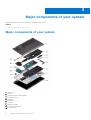
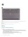
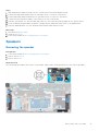
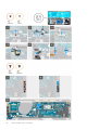
Major components of your system
1. Base cover
2. Battery
3. Solid-State Drive Thermal plate
4. Solid-State Drive
5. Speakers
6. Keyboard
7. Palmrest
8. Display Assembly
9. Power Button Module
10. System Board
3
18 Major components of your system

11. WWAN Card
12. Fan Assembly
13. Palmrest Antenna Assembly
Major components of your system 19

Disassembly and reassembly
NOTE: The images in this document may differ from your computer depending on the configuration you ordered.
Topics:
• MicroSD card
• Base cover
• Battery
• Solid-state drive
• WWAN card
• Palmrest antenna
• Heatsink assembly
• Display assembly
• Speakers
• Power button
• System board
• Keyboard
• Palmrest assembly
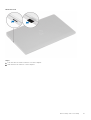
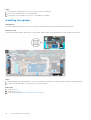
MicroSD card
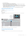
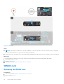
Removing the microSD card
Prerequisites
1. Follow the procedure in Before working inside your computer.
4
20 Disassembly and reassembly
Page is loading ...
Page is loading ...
Page is loading ...
Page is loading ...
Page is loading ...
Page is loading ...
Page is loading ...
Page is loading ...
Page is loading ...
Page is loading ...
Page is loading ...
Page is loading ...
Page is loading ...
Page is loading ...
Page is loading ...
Page is loading ...
Page is loading ...
Page is loading ...
Page is loading ...
Page is loading ...
Page is loading ...
Page is loading ...
Page is loading ...
Page is loading ...
Page is loading ...
Page is loading ...
Page is loading ...
Page is loading ...
Page is loading ...
Page is loading ...
Page is loading ...
Page is loading ...
Page is loading ...
Page is loading ...
Page is loading ...
Page is loading ...
Page is loading ...
Page is loading ...
Page is loading ...
Page is loading ...
Page is loading ...
Page is loading ...
Page is loading ...
Page is loading ...
Page is loading ...
Page is loading ...
Page is loading ...
Page is loading ...
Page is loading ...
Page is loading ...
Page is loading ...
Page is loading ...
Page is loading ...
Page is loading ...
Page is loading ...
Page is loading ...
Page is loading ...
Page is loading ...
Page is loading ...
Page is loading ...
Page is loading ...
Page is loading ...
-
 1
1
-
 2
2
-
 3
3
-
 4
4
-
 5
5
-
 6
6
-
 7
7
-
 8
8
-
 9
9
-
 10
10
-
 11
11
-
 12
12
-
 13
13
-
 14
14
-
 15
15
-
 16
16
-
 17
17
-
 18
18
-
 19
19
-
 20
20
-
 21
21
-
 22
22
-
 23
23
-
 24
24
-
 25
25
-
 26
26
-
 27
27
-
 28
28
-
 29
29
-
 30
30
-
 31
31
-
 32
32
-
 33
33
-
 34
34
-
 35
35
-
 36
36
-
 37
37
-
 38
38
-
 39
39
-
 40
40
-
 41
41
-
 42
42
-
 43
43
-
 44
44
-
 45
45
-
 46
46
-
 47
47
-
 48
48
-
 49
49
-
 50
50
-
 51
51
-
 52
52
-
 53
53
-
 54
54
-
 55
55
-
 56
56
-
 57
57
-
 58
58
-
 59
59
-
 60
60
-
 61
61
-
 62
62
-
 63
63
-
 64
64
-
 65
65
-
 66
66
-
 67
67
-
 68
68
-
 69
69
-
 70
70
-
 71
71
-
 72
72
-
 73
73
-
 74
74
-
 75
75
-
 76
76
-
 77
77
-
 78
78
-
 79
79
-
 80
80
-
 81
81
-
 82
82


Dell Latitude 7410 Chromebook Enterprise Owner's manual
- Type
- Owner's manual
Ask a question and I''ll find the answer in the document
Finding information in a document is now easier with AI
Related papers
-
Dell Latitude 7410 Chromebook Enterprise Owner's manual
-
Dell Latitude 3410 Owner's manual
-
Dell Vostro 3401 Owner's manual
-
Dell Vostro 3405 Owner's manual
-
Dell Vostro 3400 Owner's manual
-
-
Dell Vostro 3501 Owner's manual
-
Dell Precision 7510 Owner's manual
-
Dell Latitude 5411 Owner's manual
-
Other documents
-
Asus Chrome C423 14' CEL 4GB 64GB Grey User manual
-
Computer Gear 25-0060 Datasheet
-
Asus Chromebook Flip C214 User manual
-
-
Asus CX5500 User manual
-
LG Electronics Touch Series Education Chromebook Laptop User manual
-
Gigabyte AORUS Gen4 7300 SSD 1TB Important information
-
Acer D652N, D652NL Chromebook Tab User guide
-
LG 11TC50Q Owner's manual
-
Samsung XE513C24-K01US User manual