Page is loading ...

Q U A L I T Y F O R L I F E
Service Instructions
Electric wheelchair B500

Page 1
Service Instructions B500
Table of contents
4.1 Foreword................................................................................................. 2
4.2 Safety ...................................................................................................... 2
4.3 Maintenance schedule and tools needed ............................................... 3
4.4 Settings/substitution/replacement ......................................................... 6
4.4.1 B500 .......................................................................................................... 6
4.4.1.1 Control unit ......................................................................................................... 6
4.4.1.2 Battery ................................................................................................................ 7
4.4.1.3 Frame................................................................................................................. 9
4.4.1.4 Motors............................................................................................................... 12
4.4.1.5 Lighting ............................................................................................................. 13
4.4.1.6 Front wheels..................................................................................................... 16
4.4.1.7 Rear wheels ..................................................................................................... 18
4.4.1.8 Standard seat ................................................................................................... 19
4.4.1.9 Recaro seat...................................................................................................... 23
4.4.1.10 Seat systems options....................................................................................... 25
4.4.1.11 Lateral elements............................................................................................... 29
4.4.1.12 Foot notch ........................................................................................................ 31
4.4.1.13 Control unit accessories................................................................................... 33
4.4.1.14 Accessories...................................................................................................... 34
Table of contents

Page 2 Service Instructions B500
4.1 Foreword
Periodic servicing is important as it increases safety and extends the product’s service
life.
Every rehabilitation product needs to be inspected and serviced on a yearly basis.
We recommend to inspect, adjust, and, if necessary, service a product every six
months if the product’s users change frequently (children and young people growing
up), or when the user’s clinical picture is subject to changes.
Use only original spare parts for all service and maintenance work.
Service and maintenance work must only be performed by appropriate expert
personnel!
The service instructions refer to the spare-parts catalogue, and to the operating
instructions. All the documents should be used together.
4.2 General safety instructions
Please observe the following principles during all servicing and repair work:
- Read the service and maintenance instructions carefully before you start any work.
- Familiarize yourself with the product’s functions. If you do not know the product, you
should study the operating instructions carefully before you begin with the
inspection.
The operating instructions can be obtained from the manufacturer (see the list
of Otto Bock’s branch offices in „Otto Bock Worldwide“).
- You can also download the documents from our home page:
www.ottobock.de or www.ottobock.com.
- Use only suitable tools.
- Wear appropriate clothing, and put on gloves and goggles whenever required.
- The product must be secured so as to prevent it from overturning or falling down,
e.g., from the work bench.
- Clean and disinfect the product before starting inspection. Observe the instructions
for care in addition to any product-specific inspection instructions included in the
operating instructions.
- Screws and nuts with thread locks are used in very many screwed connections.
The corresponding nut or screw must be replaced by a new nut or screw with
a thread lock whenever a screwed connection with a thread lock needs to
be opened.
If screws or nuts with a thread lock should be unavailable, be sure to use a liquid
thread locking compound with medium strength (e.g., Euro Lock A24.20).
- Some parts are very heavy as, e.g., batteries, frame, seat, or motors!
Be sure to use a correct ergonomic approach when lifting these heavy parts.
Foreword/Safety

Page 3
Service Instructions B500
Maintenance schedule
4.3 Maintenance schedule and tools needed
The following list contains appropriate tools and auxiliary devices.
Reversible ratchet and
socket wrench inserts,
sizes 8 - 19
Wrench
sizes 8 - 24
Hexagonal
screw driver
sizes 2.5 - 8
Screwdriver
blade width
2.5; 3.5 and 5.5 mm
Crosstip screwdriver
size 2
Plastic hammer Hammer approx. 300 g
Water pump pliers
DIN 8976
grip width up to 32 mm
Diagonal cutter
Pin punch
Ø 3 mm

Page 4 Service Instructions B500
Maintenance schedule and tools needed
Drilling machine
Twist drill
Ø 4 mm
Ø 5 mm
Ø 6 mm
Carpet cutter
with a crescent-shaped
blade
Liquid
“medium strength“ thread
lock compound
Brush and
standard grease

Page 5
Service Instructions B500
Maintenance schedule and tools needed
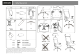
Maintenance schedule
for yearly inspection B500
Component
o ElectronicsControl unit o Fluid level
o Battery box
o Cabling
o Suspension
o Drive support
o Motor
o Rockers
o Brake release
o Tilting protection
o Cabling
1
6
7
5
4
3
2
8
9
10
11
12
13
Lateral elements
Control unit accessories
Accessories
Foot notch
Seat system options
Recaro seat system
Standard seat
Drive wheels
Front wheels
Lighting
Frame
Battery
Item
o Light holders
o Lamp housing
o Lamps
o Cabling
o Handlebar fork
o Suspension
o Handlebar lock
o Edge mounting aid
o Tires
Function Damage/
Deformation Screw
connections
o Covering
o Seat & back frame
o Seat section
o Lateral element retainer
o Seat lugs
o Tires
o Seat lock
o Subframe
o Seat modules
o Seat lugs
o Seat shell retainer
o Abduction wedge
o Head rests
o Foot notch socket
o Foot board
o Foot notch support
o Control unit holder
o Joystick
o Treatment table
o Arm rests
o Arm supports
Check (Check the box when the item is OK)
x
x
xx
x
x
xx
xx
xx
xx
xx
xx
xx
xx
xx
Servicing performed by: dated:

Page 6 Service Instructions B500
Settings/substitution/replacement
Programming and Fault Finding
When making any control settings, please refer to
the operating instructions of Penny & Giles.
These instructions include an extensive description
of all steps and notices regarding the control
system.
Refitting or replacing the control for lighting
and/or escort control
The following is required to refit the wheelchair for
lighting or escort control:
- Operator panel for lighting
- Lighting module
- Lighting
- Y cable if for lighting and
escort control
Replacing the control system:
Removal:
- Loosen the control cable
- Undo both screw connections below
the control unit
- Remove the control unit
Installation:
- Fasten the control unit using both
screw connections
- Plug in the control cable
Fastening the escort control
Use the parts provided for this purpose to fasten
the escort control to the rear of the seat or to the
head rest on Recaro seats:
- Pull off the head rest
- Insert both head rest tubes through the
bushings of the escort control
(see figure to the left)
- Fasten the head rest to the seat.
4.4 Settings/substitution/replacement
4.4.1 B500
4.4.1.1 Control unit
Escort control
Operator panel for lighting

Page 7
Service Instructions B500
Settings/substitution/replacement
Read the cautions supplied by the battery manufacturer before starting any work on the batteries!
4.4.1.2 Battery
Battery
The B500 standard version is equipped with two
12 V lead-acid batteries with a capacity of 60 Ah.
A conversion of the water-acid mix to gas will
occur for a short time during the charging process.
Check the liquid level on a weekly basis, and refill
if necessary. To do so, first remove the seat
cushion together with the seat section:
- Open the Velcro fastening of seat cushion
back and seat section, fold the seating
surface forward
- Open the catch lock at the rear end of the
battery case, and remove the cover (for
Recaro seats: open the seat lock under the
seat, and remove the cover)
For the version with spring-mounted rear wheels,
pull the lock at the rear wheelchair bottom, and
pull out the drawer with the batteries (see figure to
the left).
Charging the battery
- Connect the charger to the charge socket
at the operator panel
- Connect the charger to 230 V
The charging process will start automatically while
the LED’s are displaying the current charge status.
An incrementing LED display indicates the charg-
ing process at the operator panel:
- yellow LED lights up = battery charging
- green LED lights up = battery charged
- yellow LED flashes = fault, battery defective,
Connection insufficient...
- No LED indication = No mains voltage,
Battery charger defective
The charger has a programmed recharge phase.
You can leave the device connected without any
problems even when a full charge level is reached
although you have been charging a completely
discharged battery for 8 hours, approximately.
When charging is complete, first pull out the mains
plug, then pull out the charging plug. The B500 is
ready to operate after switching the control off and
on again.
Notes
o Charge batteries promptly whenever the
red LED’s are flashing!
o Do not charge in the green area!
o We do not assume any warranty for
damage caused by total discharge!
o Do not use any charger other than the
charger specified by Otto Bock!
o The B500 needs to be charged every month
when it is not used for a long period.

Page 8 Service Instructions B500
Settings/substitution/replacement
Caution!
o Pull out the main fuse first before starting
any work on the batteries!
o Smoking is prohibited near the charger,
and when work is performed on the
batteries!
o Avoid fire or sparking!
o Explosive gasses may be generated when
batteries are being charged, so make
certain that the gasses are properly vented!
o Be sure that the venting slots are not
covered!
Removing and installing batteries
For battery removal or installation, take off the seat
as described in section 4.4.1.8, or pull out the
battery case from the spring-mounted version.
Removal:
- Open the strap catch lock, and remove the
cover
- Remove the fuse
- Disconnect the batteries, and remove them
from the battery case
Installation:
- Place the batteries into the battery case,
and connect the batteries
- Insert the fuse
- Install the cover, and close the strap catch
lock
Replacing or removing the battery case
To replace or remove the battery case:
- Dismount the seat; for the spring-mounted
version, you only need to pull out the drawer
- Open the strap as described above
- Remove the batteries, and dismount the
battery case.

Page 9
Service Instructions B500
Settings/substitution/replacement
Replacing or removing the frame
Important!
o Turn off the B500 before starting any work
on the frame!
o Observe the cables fastened to frame, seat
or drive bracket using cable binders!
o Use caution to cut the cable binders
without damaging any cable using a
diagonal cutter or a knife!
- Place the B500 on a flat surface, and secure
it against rolling away.
-Remove the black plastic protector cap
- Use a size 19 socket and a ratchet to
unscrew and remove the front-wheel fork
- Use a suitable device to protect the wheel-
chair against overturning
- Use an Allen wrench to remove the seat:
Undo all screw connections
(four rear and two front screw connections)
which are used to secure the seat lugs to
the frame
- Unscrew all other parts fastened to the frame
(e.g., lamps and brake release)
- Remove the frame
4.4.1.3 Frame

Page 10 Service Instructions B500
Replacing or removing the drive bracket
- Turn off the B500, and pull out all plug
connections before dismounting the drive
bracket
- Undo the eight screw connections located at
the rear frame (four per side)
- Remove frame, seat, and lamps
- Remove the battery case
- Undo the two hexagon socket screws at the
drive bracket to remove the bumper (if any)
- Unscrew two screws each to dismount the
tilting protections
- Remove the tires (see section on „Replacing
the tires“)
- Pull off the wheel flanges
- Undo the brake release wires
- Unscrew the four screw connections used to
fasten the motors
Replacing or removing the rear-wheel springs
The rear-wheel springs are suspended at two
points: One point is at the top of the drive bracket
and the other on the rocker.
The rear wheels need to be dismounted before you
can remove the springs:
- Secure the B500 against slipping or overturn-
ing, and place the B500 on a support which
enables the rear wheels to rotate freely
- Dismount the wheels
- Undo the two screws used to suspend the
rear-wheel springs, and remove the rear-wheel
springs
- Install new rear-wheel springs, or change the
spring effect (turning the top plate either
down or up)
Settings/substitution/replacement

Page 11
Service Instructions B500
Removing or installing the rockers
The rear wheel rockers are fastened to the drive
bracket and rotate freely. The wheels, the rear-
wheel springs, and the motors need to be removed
before the rockers can be dismounted.
- Use a size 20 socket to unscrew and replace
the rockers
- Install the spring in one of the three rear
rocker boreholes
- Suspend the spring at the top in the last drive
bracket borehole
Installing or replacing the tilting protection
The B500 tilting protections can only be used in
pairs (one left, one right).
Use two carriage bolts to secure the tilting protec-
tions to the drive bracket (see arrow). Use an
open-end or ring spanner to either unscrew or
tighten the nuts.
Settings/substitution/replacement

Page 12 Service Instructions B500
4.4.1.4 Motors
Replacing or removing the motors
- Turn off the B500 before starting any work on
the motors
- Remove frame and seat
(refer to the sections on „Replacing or remov-
ing the frame“, and „Replacing or removing
the drive bracket“)
- Undo the brake release wire before removing
the frame (to protect the mechanism against
damage or misadjusting)
- Undo the plug-and-socket connections of the
motors
- Undo the plug-and-socket connections to the
battery case, and remove the battery case
- Unscrew the four screw connections used
to fasten the motors
Replacing or removing the brake release
- Before staring any work on the motors, turn
off the B500, secure it against rolling, and
undo the brake release
Removal:
- Use a screwdriver to remove the Bowden
cables which lead to the motors
- Unscrew the hexagon socket screw at the
frame cross strut
Installation:
- Tighten the hexagon socket screw at the
frame cross strut
- Tighten the Bowden cables which lead to the
motors using a screwdriver
Settings/substitution/replacement

Page 13
Service Instructions B500
Replacing or removing defective incandescent
lamps
Head lamp:
- Unscrew the lower screw at the head lamp
(see arrow)
- Pull off the front section, and replace the
defective lamp
Flashing light:
- Insert the screwdriver into the opening from
below, and loosen the screw with a quarter
turn
- Replace the incandescent lamp
Rear light:
- Undo the two screws to remove the cover
see arrows)
- Apply slight pressure to the right to pull
forward the incandescent lamp on the
left-hand side
- Replace the incandescent lamp
Mounting the complete light system
A new operator panel is needed to convert the
B500 for lighting. This operator panel has additional
buttons, display functions, and connecting ports.
A light module to be screwed under the seat is
supplied together with the complete light system.
- Insert the additional plug of the light operator
panel into the centre port of the light module
- Insert the light plugs into the left port or,
correspondingly, into the right port
- Secure the rear light to the last frame
borehole
- Secure the front light to the front of the seat
frame
- Use Velcro strips to fasten the bus system
plugs to the front of the frame crossbar
- Use cable binders to fasten the lighting
cables at both the frame and the seat frame
Replacing the fuse
The fuse of the B500 is located in a black case
inside the battery case.
- Open the case and replace the fuse
4.4.1.5 Lighting
Seat section
Cross bar
Settings/substitution/replacement

Page 14 Service Instructions B500
Installing and removing the light module
The light module is fastened by two screws to the
cross strut located under the seat (see arrows).
Turn off the B500, and undo all plug-and-socket
connections before starting any work on the light
module.
Settings/substitution/replacement

Page 15
Service Instructions B500
Settings/substitution/replacement
4.4.1.6 Front wheels
Replacing and removing the handlebar fork
Removal:
- Remove the black plastic dust protection cap
at the top of the handlebar fork retainer using
a screwdriver
- Use a size 20 socket to unscrew the nut, and
slide out the fork toward the bottom
Installation:
- Insert the fork, and tighten the nut using a
size 20 socket
- Put on the black plastic dust protection cap
Installing or replacing the edge mounting aid
- Unscrew and remove both hexagon socket
screws (M10x25)
- Establish the connection between spring fork
and edge mounting aid: Install the thrust plate
between spring fork and edge mounting aid,
hen screw in the threaded bolts
- Fasten the spring mounting with the leg
spring: Make certain that the inside leg of the
spring is located between fork and threaded
bush
- Secure the screw connection using „Loctite“,
and tighten the screws
Replacing or removing the springs
To replace the front-wheel fork springs, undo the
screw located in the spring. The spring effect is
modified by strongly tightening the screw.

Page 16 Service Instructions B500
Settings/substitution/replacement
Replacing or removing the handlebar lock
Removal:
- Use a pin punch to remove the cotter pin at
the top of the locking device (locking bolt and
spring will fall out below)
Installation:
- Slip the spring on the thin bolt end, and insert
spring and bolt from below into the borehole
- Set the bolt on the catch lever, and secure it
with the cotter pin
Replacing or removing the handlebar
- Use suitable objects, e.g., wood blocks to
secure the front frame part against overturning
or slipping.
The wheel must rotate freely.
- Use two size 5 Allen wrenches to remove
or install the handlebar
Replace the outer cover or the inner tube of
pneumatic tires
Caution!
Replace the outer cover whenever the tread
pattern is worn out, cracked or damaged.
Removal:
- Deflate the tire
- Unscrew all screws using an Allen key
The B600 has a divisible rim.
- Loosen the screws, separate the rim, and
replace either the inner tube or the outer
cover
- Replace the tube, or repair it using a com-
mercially available bicycle tire repair set

Page 17
Service Instructions B500
Settings/substitution/replacement
Installation:
- Insert the inner tube into the outer cover
- Fit the rim together, and all screws using
an Allen key
- Inflate the tire

Page 18 Service Instructions B500
Settings/substitution/replacement
4.4.1.7 Rear wheels
Replacing or removing the rear wheels
- Use suitable objects, e.g., wood blocks to
secure the rear frame part against overturning
or slipping.
The wheel must rotate freely.
Removal:
- Use a crosstip screwdriver to unscrew the
protection cap screwed to the rim
- Use a size 5 Allen wrench to unscrew all four
screws which hold the wheel, and remove
the wheel
Installation:
- Mount the wheel and tighten all four screws
using a size 5 Allen wrench
- Screw the protection cap to the rim using
a crosstip screwdriver
Repair instructions on how to replace the outer covers or the inner tubes of pneumatic tires.
Refer to the sections 4.4.1.6 on „Front wheels“.

Page 19
Service Instructions B500
Settings/substitution/replacement
4.4.1.8 Standard seat
Replacing the end cover
Unscrew the three screws as indicated by the
arrows.
The screw located at the centre of the end cover is
used as a stop for back angle adjustment.
Replacing and adjusting the back covering
- Remove the back covering completely, and
re-adjust the Velcro strips (as required by the
user)
- Proceed as follows to attach the Velcro strips
to the back frame (starting at the top back
tube): one narrow, one wide, two narrow, and
one wide Velcro strips
/