Asus PRIME H410M-K R2.0 User manual

Category
Motherboards
Type
User manual

This manual is also suitable for

Motherboard
PRIME H410M-K R2.0
ii
E18543
First Edition
June 2021
Copyright © 2021 ASUSTeK COMPUTER INC. All Rights Reserved.
No part of this manual, including the products and software described in it, may be reproduced,
transmitted, transcribed, stored in a retrieval system, or translated into any language in any form or by any
means, except documentation kept by the purchaser for backup purposes, without the express written
permission of ASUSTeK COMPUTER INC. (“ASUS”).
Product warranty or service will not be extended if: (1) the product is repaired, modied or altered, unless
such repair, modication of alteration is authorized in writing by ASUS; or (2) the serial number of the
product is defaced or missing.
ASUS PROVIDES THIS MANUAL “AS IS” WITHOUT WARRANTY OF ANY KIND, EITHER EXPRESS
OR IMPLIED, INCLUDING BUT NOT LIMITED TO THE IMPLIED WARRANTIES OR CONDITIONS OF
MERCHANTABILITY OR FITNESS FOR A PARTICULAR PURPOSE. IN NO EVENT SHALL ASUS, ITS
DIRECTORS, OFFICERS, EMPLOYEES OR AGENTS BE LIABLE FOR ANY INDIRECT, SPECIAL,
INCIDENTAL, OR CONSEQUENTIAL DAMAGES (INCLUDING DAMAGES FOR LOSS OF PROFITS,
LOSS OF BUSINESS, LOSS OF USE OR DATA, INTERRUPTION OF BUSINESS AND THE LIKE),
EVEN IF ASUS HAS BEEN ADVISED OF THE POSSIBILITY OF SUCH DAMAGES ARISING FROM ANY
DEFECT OR ERROR IN THIS MANUAL OR PRODUCT.
SPECIFICATIONS AND INFORMATION CONTAINED IN THIS MANUAL ARE FURNISHED FOR
INFORMATIONAL USE ONLY, AND ARE SUBJECT TO CHANGE AT ANY TIME WITHOUT NOTICE,
AND SHOULD NOT BE CONSTRUED AS A COMMITMENT BY ASUS. ASUS ASSUMES NO
RESPONSIBILITY OR LIABILITY FOR ANY ERRORS OR INACCURACIES THAT MAY APPEAR IN THIS
MANUAL, INCLUDING THE PRODUCTS AND SOFTWARE DESCRIBED IN IT.
Products and corporate names appearing in this manual may or may not be registered trademarks or
copyrights of their respective companies, and are used only for identication or explanation and to the
owners’ benet, without intent to infringe.
iii
Contents
Safety information ...................................................................................................... iv
About this guide .......................................................................................................... v
Package contents ....................................................................................................... vi
PRIME H410M-K R2.0 specications summary ....................................................... vi
Chapter 1 Product Introduction
1.1 Before you proceed ...................................................................................... 1-1
1.2 Motherboard overview ................................................................................. 1-1
1.3 Central Processing Unit (CPU) .................................................................... 1-7
1.4 System memory ............................................................................................ 1-8
Chapter 2 BIOS and RAID Support
2.1 Knowing BIOS ............................................................................................... 2-1
2.2 BIOS Setup program .................................................................................... 2-2
2.3 ASUS EZ Flash 3 ........................................................................................... 2-3
2.4 ASUS CrashFree BIOS 3 .............................................................................. 2-4
2.5 RAID congurations ..................................................................................... 2-5
Appendix
Notices ..................................................................................................................... A-1
Warranty ................................................................................................................... A-6
Service and Support ............................................................................................... A-8
iv
Safety information
Electrical safety
To prevent electrical shock hazard, disconnect the power cable from the electrical outlet
before relocating the system.
When adding or removing devices to or from the system, ensure that the power cables
for the devices are unplugged before the signal cables are connected. If possible,
disconnect all power cables from the existing system before you add a device.
Before connecting or removing signal cables from the motherboard, ensure that all power
cables are unplugged.
Seek professional assistance before using an adapter or extension cord. These devices
could interrupt the grounding circuit.
Ensure that your power supply is set to the correct voltage in your area. If you are not
sure about the voltage of the electrical outlet you are using, contact your local power
company.
If the power supply is broken, do not try to x it by yourself. Contact a qualied service
technician or your retailer.
Operation safety
Before installing the motherboard and adding components, carefully read all the manuals
that came with the package.
Before using the product, ensure all cables are correctly connected and the power cables
are not damaged. If you detect any damage, contact your dealer immediately.
To avoid short circuits, keep paper clips, screws, and staples away from connectors,
slots, sockets and circuitry.
Avoid dust, humidity, and temperature extremes. Do not place the product in any area
where it may be exposed to moisture.
Place the product on a stable surface.
If you encounter technical problems with the product, contact a qualied service
technician or your retailer.
Your motherboard should only be used in environments with ambient temperatures
between 0°C and 40°C.
v
About this guide
This user guide contains the information you need when installing and conguring the
motherboard.
How this guide is organized
This guide contains the following parts:
Chapter 1: Product Introduction
This chapter describes the features of the motherboard and the new technology it
supports. It includes descriptions of the switches, jumpers, and connectors on the
motherboard.
Chapter 2: BIOS and RAID Support
This chapter tells how to boot into the BIOS, upgrade BIOS using the EZ Flash Utility
and support on RAID.
Where to nd more information
Refer to the following sources for additional information and for product and software
updates.
1. ASUS website
The ASUS website provides updated information on ASUS hardware and software
products. Refer to the ASUS contact information.
2. Optional documentation
Your product package may include optional documentation, such as warranty flyers,
that may have been added by your dealer. These documents are not part of the
standard package.
Conventions used in this guide
To ensure that you perform certain tasks properly, take note of the following symbols used
throughout this manual.
CAUTION: Information to prevent damage to the components and injuries to yourself when
trying to complete a task.
IMPORTANT: Instructions that you MUST follow to complete a task.
NOTE: Tips and additional information to help you complete a task.
vi
Package contents
Check your motherboard package for the following items.
Motherboard 1 x PRIME H410M-K R2.0 motherboard
Cables 2 x SATA 6Gb/s cables
Miscellaneous 1 x I/O Shield
1 x M.2 ANCHOR
Application DVD 1 x Support DVD
Documentation 1 x User manual
If any of the above items is damaged or missing, contact your retailer.
PRIME H410M-K R2.0 specications summary
CPU
Intel® Socket LGA1200 for 10th Gen Intel® Core™, Pentium® Gold and Celeron®
Processors*
Supports Intel® 14nm CPU
Supports Intel® Turbo Boost Technology 2.0 and Intel® Turbo Boost Max
Technology 3.0**
*Refer to www.asus.com for CPU support list.
**Intel® Turbo Boost Max Technology 3.0 support depends on the CPU types.
Chipset Intel® H470 Chipset
Memory
2 x DIMM, Max. 64GB, DDR4 2933/2800/2666/2400/2133 MHz Non-ECC, Un-
buffered Memory*
Dual Channel Memory Architecture
Supports Intel® Extreme Memory Prole (XMP)
OptiMem
* 10th Gen Intel® Core™ i7/i9 processors support 2933/2800/2666/2400/2133 natively,
others will run at the maximum transfer rate of DDR4 2666MHz.
* Refer to www.asus.com for the Memory QVL (Qualied Vendors Lists), and memory
frequency support depends on the CPU types.
Graphics
1 x DVI-D
1 x HDMITM 1.4
*Graphics specications may vary between CPU types.
Expansion
Slots
Intel® 10th Gen Processors
1 x PCIe 3.0 x16 slot (supports x16 mode)
Intel® H470 Chipset
2 x PCIe 3.0 x1 slots
Storage
Total supports 1 x M.2 slot and 4 x SATA 6Gb/s ports
Intel® H470 Chipset
M.2 slot (Key M), type 2242/2260/2280 (supports PCIe 3.0 x4 & SATA modes)
4 x SATA 6Gb/s ports
Intel® Rapid Storage Technology supports RAID 0,1,5,10
Intel® Optane™ Memory Ready
(continued on the next page)
vii
PRIME H410M-K R2.0 specications summary
Ethernet 1 x Intel® I219-V 1Gb Ethernet
USB
Rear USB (Total 6 ports)
4 x USB 3.2 Gen 1 ports (4 x Type-A)
2 x USB 2.0 ports (2 x Type-A)
Front USB (Total 6 ports)
1 x USB 3.2 Gen 1 header supports additional 2 USB 3.2 Gen 1 ports
2 x USB 2.0 headers support additional 4 USB 2.0 ports
Audio
Realtek 7.1 Surround Sound High Denition Audio CODEC*
- Supports: Jack-detection, Multi-streaming, Front Panel Jack-retasking
- Supports up to 24-Bit/192kHz playback
Audio Features
- Audio Shielding
- Premium Japanese audio capacitors
- Dedicated audio PCB layers
* A chassis with an HD audio module in the front panel is required to support 7.1
Surround Sound audio output.
Back Panel I/O Ports
4 x USB 3.2 Gen 1 ports (4 x Type-A)
2 x USB 2.0 ports (2 x Type-A)
1 x DVI-D port
1 x HDMITM port
1 x Intel® I219-V 1Gb Ethernet port
3 x Audio jacks
1 x PS/2 Keyboard/Mouse combo port
Internal I/O
Connectors
Fan and Cooling related
1 x 4-pin CPU Fan header
1 x 4-pin Chassis Fan header
Power related
1 x 24-pin Main Power connector
1 x 8-pin +12V Power connector
Storage related
1 x M.2 slot (Key M)
4 x SATA 6Gb/s ports
USB
1 x USB 3.2 Gen 1 header supports additional 2 USB 3.2 Gen 1 ports
2 x USB 2.0 headers support additional 4 USB 2.0 ports
Miscellaneous
1 x Clear CMOS header
1 x Front Panel Audio header (AAFP)
1 x S/PDIF Out header
1 x SPI TPM header (14-1pin)
1 x 20-3 pin System Panel header with Chassis intrude function
(continued on the next page)
viii
PRIME H410M-K R2.0 specications summary
Special Features
ASUS 5X PROTECTION III
- DIGI+ VRM
- LANGuard
- Overvoltage Protection
- SafeSlot Core
- Stainless-Steel Back I/O
ASUS Q-Design
- Q-DIMM
- Q-Slot
ASUS Thermal Solution
- Aluminum heatsink design
Software
Features
ASUS Exclusive Software
Armoury Crate
AI Suite 3
- Performance and Power Saving Utility
TurboV EVO
EPU
DIGI+ VRM
Fan Xpert
- EZ update
ASUS CPU-Z
AI Charger
DAEMON Tools
Norton Anti-virus software (Free Trial version)
WinRAR
UEFI BIOS
ASUS EZ DIY
- ASUS CrashFree BIOS 3
- ASUS EZ Flash 3
- ASUS UEFI BIOS EZ Mode
BIOS 128 Mb Flash ROM, UEFI AMI BIOS
Manageability WOL by PME, PXE
Operating System Windows® 10 64-bit
Form Factor mATX Form Factor
9.6 inch x 9.6 inch (24.4 cm x 24.4 cm)
Specications are subject to change without notice.
1-1
Product Introduction
1.1 Before you proceed
Take note of the following precautions before you install motherboard components or change
any motherboard settings.
Unplug the power cord from the wall socket before touching any component.
Before handling components, use a grounded wrist strap or touch a safely grounded
object or a metal object, such as the power supply case, to avoid damaging them due
to static electricity.
Before you install or remove any component, ensure that the ATX power supply is
switched off or the power cord is detached from the power supply. Failure to do so
may cause severe damage to the motherboard, peripherals, or components.
Unplug the power cord before installing or removing the motherboard. Failure to do so can
cause you physical injury and damage motherboard components.
1.2 Motherboard overview
Place this
side towards
the rear of the
chassis
DDR4 DIMM_B2* (64bit, 288-pin module)
DDR4 DIMM_A2* (64bit, 288-pin module)
DIGI+
VRM
ASM
1442K
COM_DEBUG
CHA_FAN
CPU_FAN
M.2(SOCKET3)
PANEL
AAFP
SPDIF_OUT
CLRTC
TPM
128Mb
BIOS
SATA6G_4
SATA6G_3
SATA6G_2 SATA6G_1
USB_1112USB_910
ATX_12V
LGA1200
ATX_PWR
U32G1_56
Intel®
H470
BATTERY
HDMI
Super
I/O
2280 2260 2242
M.2(SOCKET3)
PCIE SATA IRST
3.0 X4 PCH-attached
V
PCIEX1_2
PCIEX1_1
PCIEX16
24.4cm(9.6in)
24.4cm(9.6in)
KBMS_USB_78
LAN_U32G1_12
U32G1_34
AUDIO
DVI
Ethernet
Audio
Codec
8
13
6
5
101211
3
5 21 4
9 7 14
4
1
ASUS PRIME H410M-K R2.0
Chapter 1: Product Introduction
1-2
1.2.1 Layout contents
1. CPU socket
The motherboard comes with an Intel® Socket LGA1200 designed for 10th Gen Intel® Core™,
Pentium® Gold and Celeron® Processors.
For more details, refer to Central Processing Unit (CPU).
2. DDR4 DIMM slots
The motherboard comes with Dual Inline Memory Modules (DIMM) slots designed for DDR4
(Double Data Rate 4) memory modules.
For more details, refer to System memory.
3. Expansion slots
This motherboard supports one PCIe 3.0 x16 graphics card and two PCIe 3.0 x1 network
cards, SCSI cards and other cards that comply with the PCI Express specication.
4. Fan headers
The Fan headers allow you to connect fans to cool the system.
5. Power connectors
These Power connectors allow you to connect your motherboard to a power supply. The
power supply plugs are designed to t in only one orientation. Find the proper orientation and
push down rmly until the power supply plugs are fully inserted.
Ensure to connect the 8-pin power plug.
For a fully congured system, we recommend that you use a power supply unit
(PSU) that complies with ATX 12V Specication 2.0 (or later version) and provides a
minimum power of 350W.
We recommend that you use a PSU with a higher power output when conguring a
system with more power-consuming devices. The system may become unstable or
may not boot up if the power is inadequate.
If you are uncertain about the minimum power supply requirement for your system, we
recommend you to refer to online resources for Power Supply Wattage Calculator.
6. M.2 slot (Key M)
The M.2 slot allows you to install an M.2 device such as an M.2 SSD module.
M.2 slot (Key M), type 2242/2260/2280 (supports PCIe 3.0 x4 & SATA modes).
M.2 slot supports IRST (Intel® Rapid Storage Technology).
M.2 slot can support Intel® Optane™ Memory.
FAN PWM
FAN IN
FAN PWR
GND
FAN PWM
FAN IN
FAN PWR
GND
Chapter 1: Product Introduction
1-3
7. SATA 6Gb/s ports
The SATA 6Gb/s ports allow you to connect SATA devices such as optical disc drives and
hard disk drives via SATA cables.
8. USB 3.2 Gen 1 header
The USB 3.2 Gen 1 header allows you to connect a USB 3.2 Gen
1 module for additional USB 3.2 Gen 1 ports. The USB 3.2 Gen 1
header provides data transfer speeds of up to 5 Gb/s.
The USB 3.2 Gen 1 module is purchased separately.
9. USB 2.0 headers
The USB 2.0 headers allow you to connect USB modules for additional USB
2.0 ports. The USB 2.0 headers provide data transfer speeds of up to 480
Mb/s.
DO NOT connect a 1394 cable to the USB connectors. Doing so will
damage the motherboard!
The USB 2.0 module is purchased separately.
10. Clear CMOS header
This header allows you to clear the CMOS RTC RAM data of the system setup
information such as date, time, and system passwords.
To erase the RTC RAM:
1. Turn OFF the computer and unplug the power cord.
2. Use a metal object such as a screwdriver to short the two pins.
3. Plug the power cord and turn ON the computer.
4. Hold down the <Del> key during the boot process and enter BIOS setup to re-
enter data.
If the steps above do not help, remove the onboard battery and short the two pins again to
clear the CMOS RTC RAM data. After clearing the CMOS, reinstall the battery.
11. Front Panel Audio header
This header is for a chassis-mounted front panel audio I/O module that
supports HD audio standard. Connect one end of the front panel audio
I/O module cable to this header.
We recommend that you connect a high-denition front panel
audio module to this header to avail of the motherboard’s high-
denition audio capability.
If you want to connect a high-denition front panel audio
module to this header, set the Front Panel Type item in the
BIOS setup to [HD Audio]. By default, this header is set to [HD
Audio].
USB3+5V
IntA_P1_SSRX-
IntA_P1_SSRX+
GND
IntA_P1_SSTX-
IntA_P1_SSTX+
GND
IntA_P1_D-
IntA_P1_D+
GND
PIN 1
USB3+5V
IntA_P2_SSRX-
IntA_P2_SSRX+
GND
IntA_P2_SSTX-
IntA_P2_SSTX+
GND
IntA_P2_D-
IntA_P2_D+
PIN 1
USB+5V
USB_P11-
USB_P11+
GND
NC
USB+5V
USB_P12-
USB_P12+
GND
CLRTC
+3V_BAT
GND
PIN 1
AAFP
AGND
NC
SENSE1_RETUR
SENSE2_RETUR
PORT1 L
PORT1 R
PORT2 R
SENSE_SEND
PORT2 L
HD-audio-compliant
pin definition
ASUS PRIME H410M-K R2.0
1-4
12. S/PDIF Out header
This header is for an additional Sony/Philips Digital Interface (S/PDIF) port.
Connect the S/PDIF Out module cable to this header, then install the module to
a slot opening at the back of the system chassis.
13. SPI TPM header
This header supports a Trusted Platform Module (TPM) system
with a Serial Peripheral Interface (SPI), allowing you to securely
store keys, digital certicates, passwords, and data. A TPM system
also helps enhance network security, protects digital identities, and
ensures platform integrity.
The SPI TPM module is purchased separately.
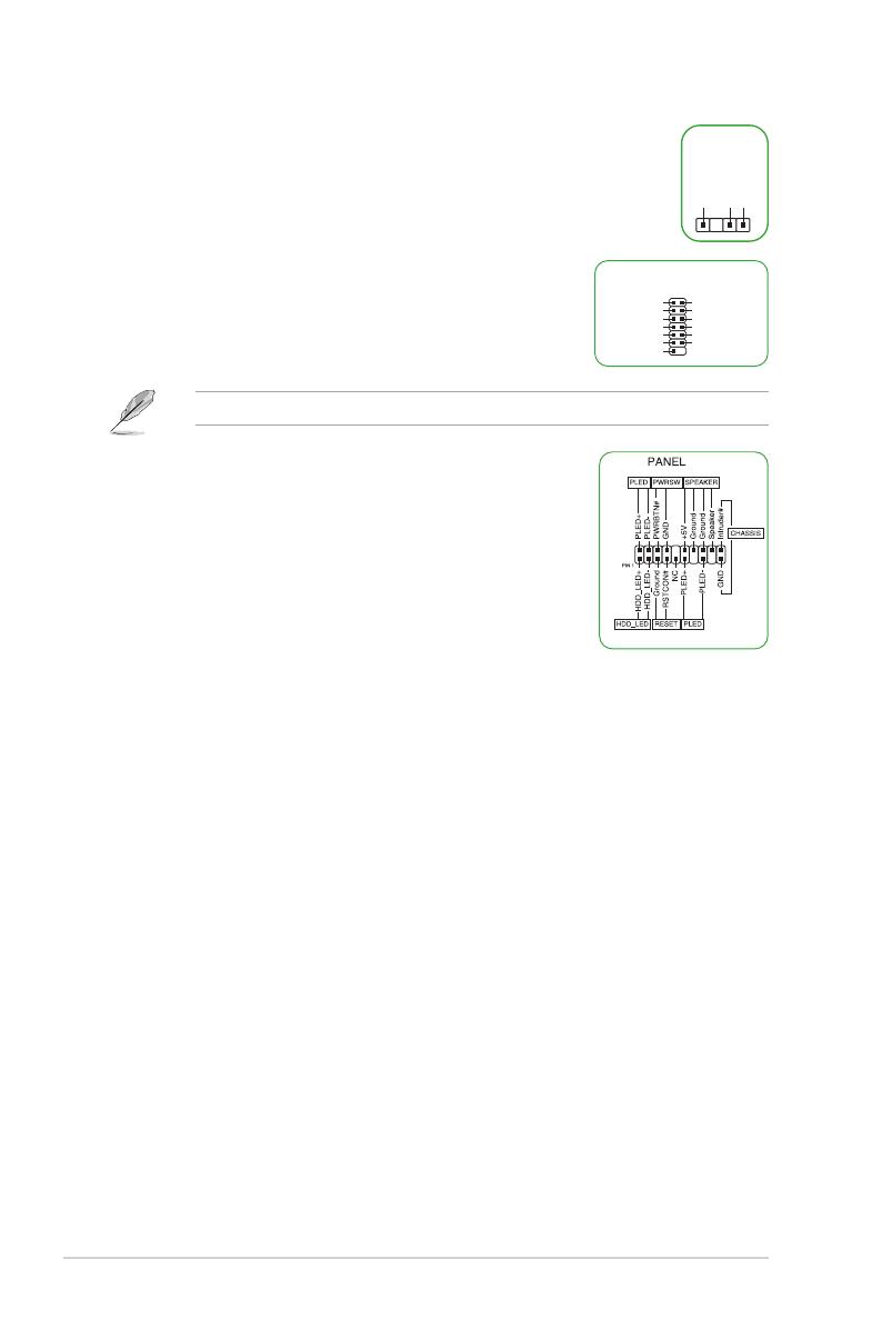
14. 20-3 pin System Panel header
This header supports several chassis-mounted functions.
System power LED (2-pin +PWR_LED-)
This 2-pin header is for the system power LED. Connect the
chassis power LED cable to this header. The system power
LED lights up when you turn on the system power, and blinks
when the system is in sleep mode.
Hard disk drive activity LED (2-pin +HDD_LED-)
This 2-pin header is for the HDD Activity LED. Connect the
HDD Activity LED cable to this header. The HDD LED lights up or ashes when data is
read from or written to the HDD.
System warning speaker (4-pin SPEAKER)
This 4-pin header is for the chassis-mounted system warning speaker. The speaker
allows you to hear system beeps and warnings.
ATX power button/soft-off button (2-pin PWR_SW)
This header is for the system power button. Pressing the power button turns the
system on or puts the system in sleep or soft-off mode depending on the operating
system settings. Pressing the power switch for more than four seconds while the
system is ON turns the system OFF.
Reset button (2-pin RESET)
This 2-pin header is for the chassis-mounted reset button for system reboot without
turning off the system power.
Chassis intrusion header (2-pin CHASSIS)
This header is for a chassis-mounted intrusion detection sensor or switch. Connect one
end of the chassis intrusion sensor or switch cable to this header. The chassis intrusion
sensor or switch sends a high-level signal to this connector when a chassis component
is removed or replaced. The signal is then generated as a chassis intrusion event.
SPDIF_OUT
+5V
SPDIFOUT
GND
TPM
PIN 1
S_SPI_TPM_IRQ#
S_SPI_TPM_CS2#
F_BIOS_WP#_R
GND
T_SPI_CLK
T_SPI_MOSI
VCCSPI
S_PLTRST#
F2_SPI_CS1#_R
+3V_SPI
F_SPI_CS0#_R
T_SPI_MISO
F_SPI_HOLD#_R
* Requires an ATX power supply
Chapter 1: Product Introduction
1-5
1.2.2 Rear panel connectors
1. PS/2 keyboard/mouse combo port. This port is for a PS/2 mouse or keyboard.
2. Ethernet port. This port allows Gigabit connection to a Local Area Network (LAN)
through a network hub. Refer to the table below for the Ethernet port LED indications.
Ethernet port LED indications
1
5 6 7 8 9
2 3 4
Ethernet port
Speed
LED
ACT/LINK
LED
Activity/Link LED Speed LED
Status Description Status Description
OFF No link OFF 10 Mbps connection
ORANGE Linked ORANGE 100 Mbps connection
BLINKING Data activity GREEN 1 Gbps connection
3. Line In port (light blue). This port connects the tape, CD, DVD player, or other audio
sources.
4. Line Out port (lime). This port connects a headphone or a speaker. In 4-channel,
5.1-channel, and 7.1-channel congurations, the function of this port becomes Front
Speaker Out.
5. USB 2.0 ports. These 4-pin Universal Serial Bus (USB) ports are for USB 2.0 devices.
6. HDMITM port. This port is for a High-Denition Multimedia Interface (HDMITM) connector,
and is HDCP compliant allowing playback of HD DVD, Blu-ray, and other protected
content.
7. DVI-D port. This port is for any DVI-D compatible device.
DVI-D can not be converted to output from RGB Signal to CRT and is not compatible with
DVI-I.
8. USB 3.2 Gen 1 (up to 5Gbps) ports. These 9-pin Universal Serial Bus (USB) ports
connect to USB 3.2 Gen 1 devices.
ASUS PRIME H410M-K R2.0
1-6
9. Microphone port (pink). This port connects a microphone.
Refer to the audio conguration table on the next page for the function of the audio ports in
2, 4, 5.1, or 7.1-channel conguration.
Audio 2, 4, 5.1 or 7.1-channel conguration
Port Headset
2-channel 4-channel 5.1-channel 7.1-channel
Light Blue (Rear panel) Line In Rear Speaker Out Rear Speaker Out Rear Speaker Out
Lime (Rear panel) Line Out Front Speaker Out Front Speaker Out Front Speaker Out
Pink (Rear panel) Mic In Mic In Bass/Center Bass/Center
Lime (Front panel) Side Speaker Out*/
Headphone
Pink (Front panel) Mic In*/
Side Speaker Out
* Multi-streaming is disabled by default, and the Lime (front panel) jack may be used as Side Speaker Out. If multi-
streaming is enabled, the Lime (front panel) jack will support headphone, and Pink (front panel) jack will support
Side Speaker Out.
To congure a 7.1-channel audio output:
Use a chassis with HD audio module in the front panel to support a 7.1-channel audio
output.
Chapter 1: Product Introduction
1-7
1.3 Central Processing Unit (CPU)
This motherboard comes with an Intel® Socket LGA1200 designed for
10th Gen Intel® Core™, Pentium® Gold and Celeron® Processors.
Unplug all power cables before installing the CPU.
Ensure that you install the correct CPU designed for the
LGA1200 socket only. DO NOT install a CPU designed for LGA1150, LGA1151,
LGA1155 and LGA1156 sockets on the LGA1200 socket.
Upon purchase of the motherboard, ensure that the PnP cap is on the socket and
the socket contacts are not bent. Contact your retailer immediately if the PnP cap
is missing, or if you see any damage to the PnP cap/socket contacts/motherboard
components.
Keep the cap after installing the motherboard. ASUS will process Return Merchandise
Authorization (RMA) requests only if the motherboard comes with the cap on the
LGA1200 socket.
The product warranty does not cover damage to the socket contacts resulting from
incorrect CPU installation/removal, or misplacement/loss/incorrect removal of the PnP
cap.
Installing the CPU
1
4
Apply the Thermal Interface Material to the CPU heatsink and CPU before you install the
heatsink and fan if necessary.
2
3
A
B
A
B
C
D
5
4
4
5
ASUS PRIME H410M-K R2.0
1-8
1.4 System memory
This motherboard comes with two Double Data Rate 4 (DDR4) Dual Inline Memory Module
(DIMM) sockets. The gure illustrates the location of the DDR4 DIMM sockets:
Channel Sockets
Channel A DIMM_A2*
Channel B DIMM_B2*
DIMM_B2*
DIMM_A2*
You may install varying memory sizes in Channel A and Channel B. The system
maps the total size of the lower-sized channel for the dual-channel conguration. Any
excess memory from the higher-sized channel is then mapped for single-channel
operation.
Always install DIMMs with the same CAS latency. For optimal compatibility, we
recommend that you install memory modules of the same version or date code (D/C)
from the same vendor. Check with the retailer to get the correct memory modules.
A DDR4 memory module is notched differently from a DDR, DDR2, or DDR3 module.
DO NOT install a DDR, DDR2, or DDR3 memory module to the DDR4 slot.
The default memory operation frequency is dependent on its Serial Presence Detect
(SPD), which is the standard way of accessing information from a memory module.
Under the default state, some memory modules for overclocking may operate at a
lower frequency than the vendor-marked value.
For system stability, use a more efcient memory cooling system to support a full
memory load (2 DIMMs).
Refer to www.asus.com for the latest Memory QVL (Qualied Vendors Lists), and
memory frequency support depends on the CPU types.
Recommended memory congurations
DIMM_B2*
DIMM_B2*
DIMM_A2* DIMM_A2*
Chapter 1: Product Introduction
1-9
Installing a DIMM
1 2
B
A
A
To remove a DIMM
B
A
ASUS PRIME H410M-K R2.0
1-10 Chapter 1: Product Introduction
2-1
BIOS and RAID Support
2
2.1 Knowing BIOS
The new ASUS UEFI BIOS is a Unied Extensible Interface that complies with UEFI
architecture, offering a user-friendly interface that goes beyond the traditional keyboard-
only BIOS controls to enable a more exible and convenient mouse input. You can easily
navigate the new UEFI BIOS with the same smoothness as your operating system. The
term “BIOS” in this user manual refers to “UEFI BIOS” unless otherwise specied.
BIOS (Basic Input and Output System) stores system hardware settings such as storage
device conguration, overclocking settings, advanced power management, and boot
device conguration that are needed for system startup in the motherboard CMOS. In
normal circumstances, the default BIOS settings apply to most conditions to ensure
optimal performance. DO NOT change the default BIOS settings except in the following
circumstances:
An error message appears on the screen during the system bootup and requests you
to run the BIOS Setup.
You have installed a new system component that requires further BIOS settings or
update.
Inappropriate BIOS settings may result to instability or boot failure. We strongly
recommend that you change the BIOS settings only with the help of a trained service
personnel.
BIOS settings and options may vary due to different BIOS release versions. Please refer to
the latest BIOS version for settings and options.
For more information on BIOS congurations, please refer to
https://www.asus.com/support, or download the BIOS manual
by scanning the QR code.
ASUS PRIME H410M-K R2.0
2-2
2.2 BIOS Setup program
Use the BIOS Setup to update the BIOS or congure its parameters. The BIOS screens
include navigation keys and brief onscreen help to guide you in using the BIOS Setup
program.
Entering BIOS at startup
To enter BIOS Setup at startup, press <Delete> or <F2> during the Power-On Self Test
(POST). If you do not press <Delete> or <F2>, POST continues with its routines.
Entering BIOS Setup after POST
To enter BIOS Setup after POST:
Press <Ctrl>+<Alt>+<Delete> simultaneously.
Press the reset button on the system chassis.
Press the power button to turn the system off then back on. Do this option only if you
failed to enter BIOS Setup using the rst two options.
After doing either of the three options, press <Delete> key to enter BIOS.
Ensure that a USB mouse is connected to your motherboard if you want to use the
mouse to control the BIOS setup program.
If the system becomes unstable after changing any BIOS setting, load the default
settings to ensure system compatibility and stability. Select the Load Optimized
Defaults item under the Exit menu or press hotkey <F5>.
If the system fails to boot after changing any BIOS setting, try to clear the CMOS and
reset the motherboard to the default value.
The BIOS setup program does not support Bluetooth devices.
BIOS menu screen
The BIOS Setup program can be used under two modes: EZ Mode and Advanced Mode.
You can change modes from Setup Mode in Boot menu or by pressing the <F7> hotkey.
Chapter 2: BIOS and RAID Support
  • Page 1 1
  • Page 2 2
  • Page 3 3
  • Page 4 4
  • Page 5 5
  • Page 6 6
  • Page 7 7
  • Page 8 8
  • Page 9 9
  • Page 10 10
  • Page 11 11
  • Page 12 12
  • Page 13 13
  • Page 14 14
  • Page 15 15
  • Page 16 16
  • Page 17 17
  • Page 18 18
  • Page 19 19
  • Page 20 20
  • Page 21 21
  • Page 22 22
  • Page 23 23
  • Page 24 24
  • Page 25 25
  • Page 26 26
  • Page 27 27
  • Page 28 28
  • Page 29 29
  • Page 30 30
  • Page 31 31
  • Page 32 32

Asus PRIME H410M-K R2.0 User manual

Category
Motherboards
Type
User manual
This manual is also suitable for

Ask a question and I''ll find the answer in the document

Finding information in a document is now easier with AI