Page is loading ...

ICON100-20011128
1
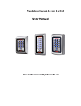
STAR ICON100
ID TECK
ACCESS CONTROLLER
USER’S MANUAL
STAR ICON100
Access Controller
ID TECK Co. Ltd.

ICON100-20011128
2
STAR ICON100
ID TECK
ACCESS CONTROLLER
Table of Contents
1. Important Safety Instructions 3
2. General 3
3. Features 4
4. Specification 4
5. Identifying Supplied Parts 5
6. System Description 5
7. Connection 6
8. System Application 8
9. Wiring for Network 10
10. Functions 10
11. Operation 12
12. Basic settings 13
13. Setting Changes 18
14. Operating status indications 41
15. Warranty and Service 42

ICON100-20011128
3
STAR ICON100
ID TECK
ACCESS CONTROLLER
1. Important Safety Instructions
When using your STAR ICON100, basic safety precautions should always be followed to reduce the
risk of fire, electrical shock, and injury to persons. In addition, the following safety guides should also be
followed:
1. Fully read and understand all instructions and follow them completely.
2. Follow all warnings and instructions marked on the product.
3. Do not use liquid or aerosol cleaners. Use a damp cloth for cleaning. If necessary, use mild soap.
4. Do not use this product near water.
5. Only operate this product using the type of power source indicated. If you are not sure of the type of
power supplied to your installation site, consult your dealer or local power company.
6. Never insert objects of any kind into the product or through the cabinet slots as they may touch
voltage points and/or short circuit parts possibly resulting in fire or electric shock. Never spill liquid of
any kind on the product.
7. Never disassemble this product by yourself; take the unit to a qualified service center whenever
service or repair is required. Opening or removing the covers may expose you to dangerous voltages
or other risks. Also, incorrect reassembly can cause electric shock when the unit is subsequently used.
8. Unplug this product from the Direct Current (DC) power source and refer to qualified service
personnel under these conditions:
a. When the power supply cord or plug is damaged or frayed.
b. If liquid has been spilled on the product.
c. If the product does not operate normally after following the operating instructions in this manual.
Adjust only those controls that are covered by the operating instructions in this manual. Improper
adjustment of other controls that are not covered by this manual may damage the unit and will
often require extensive work by a qualified technician to restore normal operation.
d. If the product exhibits a distinct change in performance.
2. General
The STAR ICON100 is an intelligent single door access controller with a powerful 8 bit
microprocessor to meet the market requirements for a simple and cost-effective access controller. It
is designed to achieve low cost as well as high security, convenience and reliability. This user friendly
device allows you to register 500 ~ 10,000 ID numbers and it can keep 2,500 ~ 7,250 events.
Number of ID & Event can be exchanged under the ratio of 2 to 1 which means every 500 users can
be convert to 250 events. Independent 4 input ports can be connected with various devices such as
exit button, door contact, PIR sensor, fire sensors. Extra reader port allows for user to add external
RF reader for Anti pass back operation. Star ICON100 can be used as not only a standalone access
controller but also a network system communicating via RS-422 and RS-232 communication port. All
setting values including ID numbers, inputs/outputs, real-time clock and time schedule, all event
transaction reports can be downloaded/uploaded from/to the host computer. The STAR ICON100 will
provide you an accurate access control for single door and 3 LED indicators inform you all system
operating status at real time. The STAR ICON100 access controller will give you field proven
reliability and cost-effective solution wherever access controls and high security are required

ICON100-20011128
4
STAR ICON100
ID TECK
ACCESS CONTROLLER
3. Features
- Single Door Control Panel
- 2 Reader ports with 26bit Wiegand format
- Data memory programmable
Card holder records -------- 500 to 10,000
Off-line stored events ------ 7,250 to 2,500
- Anti-Pass Back Operation
- Duress mode Operation
- Various Time Schedule Operation
- 4 independent input ports(Exit button, Door contact, Aux #1, Aux #2)
- 4 output ports including 2 Form-C Relays
- All setting values are user programmable from the keypad or from the application software
- Door Lock and Unlock functions
- One RS-232 port and one RS-422 communication port for easy interfacing to Host computer
- Communication Address selectable up to 32ch
- Baud rate selectable at 4800, 9600(default),19200bps
- 3 LEDs (red, green, and yellow) for system operation status
- Door open by compulsion and Door open alarm
4. Specification
CPU : 8bit Microprocessor
Memory : Program memory(64KB ROM)
Data memory(128KB RAM : battery backup)
Power : DC 12V/ 150mA (max.)
Card Holders/Event buffers : Memory programmable for:
Card holder records -------- 500 to 10,000
Off-line stored events ------ 7,250 to 2,500
Reader ports/Data format : 2 Reader port / 26bit wiegand format
Input/Output : 4 Inputs(Exit button, Door contact, Aux #1, Aux #2),
max. rating at DC12V/20mA
: 2 Relay outputs : DC12V~24V/2A max.
: 2 TTL outputs : DC5V/20mA
Communication : One RS-232 port and one RS-422 port
4800, 9600(default), 19200 bps Baud Rate .
LED : 3 LEDs (red, green, and yellow)
Operating environment range : -35°C to +65°C, 10% to 90% Humidity
Mounting : 4 screw mount
Weight : 170g
Dimensions : 137mm(5.4 ”) x137mm(5.4 ”)
Self diagnostic : Yes
Reset : Power on reset & watch dog timer
Optional:
Keypad : 16 Numeric Keypad
LCD : 1x LCD module, 2Lines x 16ch, 65.6 x 13,8mm view area

ICON100-20011128
5
STAR ICON100
ID TECK
ACCESS CONTROLLER
5. Identifying Supplied Parts
Please unpack and check the contents of the box.
6. System Description
Main Unit
( 1 )
Manual
( 1 )
16 Numeric Keypad Wafer
LCD Wafer
System Operation
Status LED
Power
TTL1,2
Relay1,2
RS-232
RS-422
Input
Reader2
Reader1
DIP S/W
LED Control

ICON100-20011128
6
STAR ICON100
ID TECK
ACCESS CONTROLLER
7. Connection
Setting address by the addressing DIP switch
1. Initial status
Initial status of the DIP switch is as follows.
The address set by the DIP switch is to be used when operating with application program, so it
must be set equal to application's value. If necessary, see the application program manual.
On
Off
12345678

ICON100-20011128
7
STAR ICON100
ID TECK
ACCESS CONTROLLER
2. Addressing the unit
Table 1 : The relation between Setting and Dip switch
00 01 02 03 04 05 06 07 08 09 10 11 12 13 14 15
1 On Off
On Off On Off On Off On Off On Off On Off On Off
2 On On Off Off On On Off Off On On Off Off On On Off Off
3 On On On On Off Off Off Off On On On On Off Off Off Off
4 On On On On On On On On Off Off Off Off Off Off Off Off
5 On On On On On On On On On On On On On On On On
6 On On On On On On On On On On On On On On On On
7 On On On On On On On On On On On On On On On On
8 On On On On On On On On On On On On On On On On
3. Initializing the unit.
Toggle the switch 8 to 'off' and toggle it back to 'on' when the power is on. Then you will see a
message showing the initialization is completed on the LCD. Press the <ESC> key and finish.
16 17 18 19 20 21 22 23 24 25 26 27 28 29 30 31
1 On Off On Off On Off On Off On Off On Off On Off On Off
2 On On Off Off On On Off Off On On Off Off On On Off Off
3 On On On On Off Off Off Off On On On On Off Off Off Off
4 On On On On On On On On Off Off Off Off Off Off Off Off
5 Off Off Off Off Off Off Off Off Off Off Off Off Off Off Off Off
6 On On On On On On On On On On On On On On On On
7 On On On On On On On On On On On On On On On On
8 On On On On On On On On On On On On On On On On
On
Off
12345678

ICON100-20011128
8
STAR ICON100
ID TECK
ACCESS CONTROLLER
8. System Application
8-1. Power Connection
- Connect (+) wire of DC 12V power to +12V(power port 1) port
- Connect Power GND (-) wire of DC 12V to GND(power port 2) port
8-2. Door Lock Connection(Relay1)
8-2-1 Connection of POWER FAIL SAFE: Door Lock
- Connect Door RELAY (COM port) to DC +12V (be sure that the existing power supply has
enough capacity to support this accessory or upgrade to a sufficient one.)
- Connect (+) wire of Door Lock to Door RELAY (NO port) port.
- Connect (-) wire of Door Lock to Power GND (-) port.
8-2-2 Connection of POWER FAIL SECURE: Door Lock
- Connect Door RELAY (COM port) to DC +12V (be sure that the existing power supply has
enough capacity to support this accessory or upgrade to a sufficient one.)
- Connect (+) wire of Door Lock to Door RELAY (NC port).
- Connect (-) wire of Door Lock to Power GND(-).
8-3. Alarm Device Connection(Relay2)
- Connect Alarm RELAY (COM port) to DC +12V (be sure that the existing power supply has
enough capacity to support this accessory or upgrade to a sufficient one.)
D0
GND
D0
D1
+12V
GND
DC12V
POWER
SUPPLY
PIR Sensor
Reader1
EXIT
Button
Door
Contact
GND
Input 2
Input 1
D1
+12V
+12VGND
GND
Input 3
GND
GND
Relay1
Relay2
Door Lock
Siren
Reader2

ICON100-20011128
9
STAR ICON100
ID TECK
ACCESS CONTROLLER
- Connect (+) wire of Alarm Device to Alarm RELAY (NO port) wire.
- Connect (-) wire of Alarm Device to Power GND (-) wire.
8-4. Exit Button Connection
- Connect one of the wires of Exit Button to Exit Button Input.
- Connect the other wire of Exit Button to Power GND(-).
8-5. Door Contact Sensor Connection
- Connect Door Contact sensor(COM) wire to Door Contact Input.
- Connect Door Contact sensor(NO) wire to Power GND(-).
8-6. Auxiliary Input Device Connection (Applied to Input 1,2)
- Connect one wire of the Auxiliary Input Device to the Input(Input 1,2).
- Connect the other wire of Auxiliary Input Device to Power GND(-).
8-7. Wiegand Input Connection From Wiegand Reader(1, 2)
- Connect (+) wire of Reader(1,2) to +12V port of Main Unit.
- Connect (-) wire of Reader(1,2) to GND (-) port of Main Unit.
- Connect Wiegand output DATA0 wire of the additional Reader(1,2) to DATA0(Reader1,2).
- Connect Wiegand output DATA1 wire of the additional Reader(1,2) to DATA1(Reader1,2).
- When installing readers, reader1 set for entry and reader2 set for exit.
* Qualified card readers: 26bit wiegand format reader
EXAMPLE: ID_TECK : RF series, RFK 101
MOTOROLA : ARK501+
BALOGH : Hyper_X
8-8. RS-232 Communication Port Connection
9-pin connector (COM Port, female) is required to connect serial communication RS-232
between Main Unit and Personal Computer.
- Connect RS-232-TX of main unit to pin number 2 of 9-pin connector.
- Connect RS-232-RX of main unit to pin number 3 of 9-pin connector.
- Connect RS-232-GND of Main Unit to pin number 5 of 9-pin connector.
- Plug in 9-pin connector to COM1 or COM2 Port of Personal Computer.
- Install and run Application Software.
8-9. RS-422 Communication Port Connection
RS-422/RS-232 converter is required to connect serial communication RS-422 between Main
Unit and Personal Computer.
- Plug in RS-232 9-pin connector of RS-422/RS-232 converter to COM1 or COM2 Port of
Personal Computer.
- Connect RS-422-TX(-) of Main Unit to RX(-) port of converter.
- Connect RS-422-TX(+) of Main Unit to RX(+) port of converter.
- Connect RS-422-RX(-) of Main Unit to TX(-) port of converter.
- Connect RS-422-RX(+) of Main Unit to TX(+) port of converter.
- Install and run Application Software.

ICON100-20011128
10
STAR ICON100
ID TECK
ACCESS CONTROLLER
9. Wiring for Network
10. Functions
10-1. Standalone Operation
The STAR ICON100 is capable of having two readers (entry and exit). The unit receives card data
signals from the RF readers and determines whether or not to unlock the door. When an input signal is
sent, for example from an activated sensor or if the exit button pressed, the controller generates and
logs an appropriate response. All events are kept in its own memory and sent to the host computer.
The access controller is a true standalone device that in the event of a malfunction, will not affect other
units, even if used in conjunction with one another.
10-2. Operation with Host Computer
All event data can be managed via the host computer. The data transmitted from the controller can be
displayed and stored on the host PC.
10-3. Keypad
In the event that a host PC is not used, the integrated keypad and LCD can also be used for the entire
programming process.

ICON100-20011128
11
STAR ICON100
ID TECK
ACCESS CONTROLLER
10-4. Cooperation with Fire Detection Equipment
The STAR ICON100 access controller and fire detection equipment can cooperate to unlock the door
in case of fire.
10-5. Anti-Pass-Back
Using an additional RF reader for exiting, the Anti-Pass-Back mode can be utilized. Anti-pass-back
prevents a registered user from exiting if the user did not properly register when entering. Likewise if
the user has exited without verification by the unit, the user will not be allowed entry on their next
attempt.
10-6. Data Backup
The controller retains all user information and event data for over a week, even if the event of loss of
power. Using a battery back up the unit can operate normally for a significant time period, depending on
the power of the battery used.
10-7. Inputs/ Outputs
The STAR ICON100 access controller has four input ports(two relay output ports and two TTL output
ports) which can be used to manipulate a wide variety of controls.
10-8. Time Schedule
You can program periods of time when each person(ID number) can access the door. Each user can
be programmed individually to address work shifts, weekends and holidays. All scheduling can be
programmed through the keypad and LCD or via the software program on the host computer. Also you
can set periods of time about output following input, and only output(see 13.2.3 page29), the former
correspond to Input, the latter correspond to Output. So, you can set Input and Output according to
each T/S. All these can be defined through the setup menu or application program.
10-9. Output Behavior Setup
The two relays outputs, two TTL outputs, buzzer sound, etc. are customizable. They may be activated
or deactivated, and in active mode may be programmed for different lengths of time, different
responses to inputs, and can be set through the setup menu or the application program.
10-10. Door Open by Compulsion and Door Open Alarm
When door is opened by compulsion, Door Contact output(see 13.2.3 page29) is generated. And,
when the door is being opened by normal operation, after 20 sec. door-open alarm(blink buzzer) will be
generated until the door is closed.
10-11. Duress Mode
In case of Duress, enter the 2 digit Duress Password and press <ENT> and open the door using
general process. If you registered ID, then duress output(see 13.2.3 page29) will be generated.
10-12. Programmable ID/EVENT memory
This user friendly device allows you to register 500 ~ 10,000 ID numbers and it can keep 2,500 ~
7,250 events. Number of ID & Event can be exchanged under the ratio of 2 to 1 which means every
500 users can be convert to 250 events.

ICON100-20011128
12
STAR ICON100
ID TECK
ACCESS CONTROLLER
11. Operation
11-1. Normal Operation Mode (Safe Mode)
When the Main Unit operates in standby mode(waiting for RF card), the red LED is lit.
11-2. Open the Door
When a registered card(or PIN) is read, the Door will open for 3 seconds.(default)
.
Registered Card
11-3. Exit (Open the Door)
To request for exit from the inside, an Exit Button(or Exit Reader) can be used to open the door.
Registered Card
11-4. Action And Alarm Caused by Unregistered Card
When an unregistered card is read the access is denied and the alarm can be activated for 3
seconds along with a buzzer sound.
Unregistered Card
(If you do not want to activate the Alarm in case of unregistered access attempt, then you can
change this setting as shown in section 13.2.3.)
Reader
Reader
Reader

ICON100-20011128
13
STAR ICON100
ID TECK
ACCESS CONTROLLER
12. Basic settings
12.1 Basic operation
LCD display model name,
current date and time
POWER ON
H/W RESET MODE
INITIAL BEEP
LCD display : STAR ION100[F1]
MM/DD hh/mm/ss
SYSTEM READY
GENERAL BOOT
ID INPUT ?
(Card or Key)
NO
YES
MASTER ID ?YES
ENTER SETUP MENU
END SETTING ?
REGISTERED ID ?
CHECK REGISTERED ID FLAGS
RIGHT ?
OUTPUT CONTROL OF EACH STATUS
NO
YES
YES
NO
NO
YES
NO
SETTING IN SETUP
MODE
You can select output of each
status in setup menu F2
P/W, T/S, Door,
Duress mode,
APB, etc...
NO
DURESS P/W ?
YES
DURESS FLAG SET
Turn ON DIP Switch No. 8
"Turn ON DIP.8"
"Turn OFF Power..."
Turn off Power
System initialization completion
Turn OFF DIP Switch No. 8
INITIAL BEEP
LCD display : STAR ION100[F1]
MM/DD hh/mm/ss

ICON100-20011128
14
STAR ICON100
ID TECK
ACCESS CONTROLLER
12.2 System initialization by using the addressing DIP switch
You can initialize the unit, using the DIP switch. Toggle the switch 8 to 'off' and toggle it back to
'on' when the power is on. Then you will see a message showing the initialization is completed
on the LCD. Press the <ESC> key and finish. The illustration below shows the process.
POWER ON
You can initialize the unit, using
the DIP switch. Toggle the switch
No. 8 to 'off'
Turn ON DIP Switch No. 8
"Turn ON DIP.8"
"Turn OFF Power..."
Turn off Power
System initialization completion
INITIAL BEEP
LCD display : STAR ICON100 [F1]
MM/DD hh/mm/ss
Figure1. DIP switch
On
Off
12345678
On
Off
12345678
12.3 Enter into setup menu
To set or to change the STAR ICON100 access
controller's operation, enter the eight-digit Master
number(factory setting '00000000' ).
Note You can change the Master ID. (see 13.1.7)
INITIAL DISPLAY
(MODEL NAME, CURRENT TIME)
ID INPUT ?
MASTER ID ?
YES
YES
NO
OPERATE GENERAL
MODE
SETUP MODE
NO
Operation of Registered ID
Operation of Unregistered ID
Operation of Duress mode

ICON100-20011128
15
STAR ICON100
ID TECK
ACCESS CONTROLLER
12.4 Setting the Date and Time
Select ‘Time setting’ in “Setup menu F1” and enter the data of year /month /date /hour
/minute /second /day (15digit) as the illustration below shows.
You will see the adjusted time on the LCD when finished.
Initial display after time setting
“Year/Month/Day/Hour/Min./Sec./Day”
Initial display
STAR ICON100 [F1]
MM/DD hh:mm:ss
Master ID
“00000000”
Select ‘Time Setting’
menu(Setup menu F1)
TIME SETTING
MM/DD hh:mm:ss
YYYYMMDDhhmmssW
200107050918305
ENT
TIME SETTING
07/05 09:18:30
ESC
STAR ICON100 [F1]
07/05 09:18:30
: After change Master
: Initial Master
ENT
Day code 1 : Sun., 2 : Mon., 3 : Tue., 4 : Wed., 5 : Thu., 6 : Fri., 7 : Sat.
For exam
p
le : '200106071330253' for Tuesda
y,
June 7
,
2001 01:30:25PM.

ICON100-20011128
16
STAR ICON100
ID TECK
ACCESS CONTROLLER
12.5 Registering Cards
You can register Cards(or PIN) to the system. (See, 13.3.1)
Select ‘ID REGISTRATION’ in Setup menu 3, follow through illustration below shows.
1. Registration by RF Cards
2. Registration by Key_pad
Initial display
STAR ICON100 [F1]
MM/DD hh:mm:ss
Master ID
“00000000”
Select ID Registration
menu (Setup menu F3)
ID REGISTRATION
ENT
ID REGISTRATION
1-Card, 2-Key
Input PW/TS/RD + <ENT>
Success
“1”Key
Scanning…
Approach card
reader1
25500100
PW1234 TS00 RD3
Completion
Input PW/TS/RD + <ENT>
“2”key
Input Registration
key (8digit+<ENT>)
00000100
PW1234 TS00 RD3
ID [________]
PW____ TS__ RD_
Success
Completion

ICON100-20011128
17
STAR ICON100
ID TECK
ACCESS CONTROLLER
When registering cards,
1. The 'PW' is for password input. The password is needed to access doors when the controller is
operating in RF + PW mode. But regardless of the operating mode, it is necessary to input a
password when registering.
2. The 'TS' is for Time Schedule index(01~10). To control the accessible periods of time for each
card, set Time schedules first(see 13.2.1 page27) and enter the Time Schedule index number
here.
If there is no need to apply the Time Schedule(anytime accessible with that card), enter '00' for
the value.
3. The 'RD' is for selecting accessible reader for the card. Usually ‘3’ (both readers) is used when
using both entry and exit readers. If '1' is entered for the value, only reader 1 will recognize the
card and reader 2 will deny access, indicating 'ACCESS DOOR ERR' on the LCD (this is also
the choice when using a one reader setup, meaning using one reader for entry and no reader
for exit). Likewise, when '2' is entered, only the reader 2 is accessible with that card and reader
1 access will be denied. And again, both readers are accessible when '3' is entered for the 'RD'
value.

ICON100-20011128
18
STAR ICON100
ID TECK
ACCESS CONTROLLER
13. Setting Changes
To set or to change the STAR ICON100 access
controller's operation, enter the eight-digit Master
number(factory setting '00000000' ).
Note You can change the Master ID. (see 13.1.7)
INITIAL DISPLAY
(MODEL NAME, CURRENT TIME)
ID INPUT ?
MASTER ID ?
YES
YES
NO
OPERATE GENERAL
MODE
SETUP MODE
NO
Operation of Registered ID
Operation of Unregistered ID
Operation of Duress mode
1. MODE SELECTION
2. TIME SETTTING
3. APB SETUP
4. COMM ID
5. BAUD RATE
6. EVENT CLEAR
7. MASTER ID CHANGE
8. SYSTEM INITIALIZE
9. CARD ID CLEAR
10. TIME SCHE CLEAR
11. RF_PIN_INPUT
12. EVENT MEMORY
13. DURESS MODE SET
SETUP F1 MODE SETUP F2 MODE
1. TIME SCHEDULE
2. HOLIDAY SETTING
3. IN/OUT DEFINE
4. HOLIDAY INDEX
5. MODE INDEX
1. ID REGISTRATION
2. ID DELETE
3. ID LIST
4. REG. ID COUNT
5. ID COUNT
SETUP F3 MODE
1. VERSION
2. SRAM TEST
3. OUTPUT TEST
4. LCD TEST
5. KEYPAD TEST
6. READER TEST
7. INPUT TEST
8. COMM TEST
SETUP F4 MODE
To set or to change the STAR ICON100’s operation, enter the eight-digit Master number
(factory setting “00000000”) <ENT>key, then you are ready to set or to change all the settings
of the controller. There are four main setup menus. You need to press <F1> key for setup menu
F1, <F2> key for setup menu F2, <F3> key for setup menu F3 and <F4> key for setup menu F4.
Note
You can change the Master number. (see 13.1.7)

ICON100-20011128
19
STAR ICON100
ID TECK
ACCESS CONTROLLER
13.1 Setup Menu F1
MODE SELECTION
RF+P/W( PassWord )
TIME SETTING
APB SETUP
NOT USE (DEFAULT)
USE
RF Only (DEFAULT)
COMM ID
SEARCHING KEY(key<4> or <6>)
SEARCHING KEY(key<4> or <6>)
SEARCHING KEY(key<4> or <6>)
SEARCHING KEY(key<4> or <6>)
SEARCHING KEY(key<4> or <6>)
SEARCHING KEY(key<4> or <6>)
SEARCHING KEY
ALL CLEAR
BAUD RATE 4800
9600 (DEFAULT)
19200
38400
EVENT CLEAR YES
NO
MASTER ID CHANGE
SEARCHING KEY(key<4> or <6>)
KEY
15 digit key in
Note There are four main setup menus. You need to press <F1> key for setup menu F1, <F2>
key for setup menu F2, <F3> key for setup menu F3 and <F4> key for setup menu F4. The
keys <4>, <6>, <2> and <8> are used to change submenus or to select values, <ENT> to
select and set, <ESC> to go to upper step or to leave setup mode. When selecting mode or
setting values is completed, in all kind of menu, the figure on the LCD returns to the first figure
of that menu. Then, for the next setting, use <4> and <6> keys(searching key).

ICON100-20011128
20
STAR ICON100
ID TECK
ACCESS CONTROLLER
13.1.1 Changing Operating Mode
DURESS MODE SET NOT USE (DEFAULT)
USE
DURESS P/W SETTING
TIME SCHE CLEAR YES
NO
RF_PIN_INPUT ENABLE
DISABLE (DEFAULT)
SEARCHING KEY(key<4> or <6>)
EVENT MEMORY NOT USE
USE (DEFAULT)
SEARCHING KEY(key<4> or <6>)
SEARCHING KEY(key<4> or <6>)
SEARCHING KEY(key<4> or <6>)
SEARCHING KEY
SYSTEM INITIALIZE YES
NO
CARD ID CLEAR
YES
NO
SEARCHING KEY(key<4> or <6>)
SEARCHING KEY(key<4> or <6>)
MODE SELECTION
RF+P/W( PassWord 4 digit )
RF Only (DEFAULT)'ENT'
SEARCHING KEY(key<4> or <6>)
/