
BROWN indicates FLOATING PIECES
BLACK indicates RIGID PIECES
EDECK
COMPOSITE DECK SYSTEM
INSTALLATION GUIDE
EASY AS 1-2-3
®
1
© 2004 McFarland Cascade

EASY
-
TO
-
USE MATERIALS
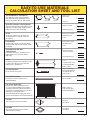
CALCULATION SHEET AND TOOL LIST
2
Quick Clip Fasteners & Pinning Screws
Clips fasten deck boards to joists with #6 x 1 1/2˝ self
tapping SS screws (Box of 100). Ten #8 x 1 1/4˝ SS
pinning screws and one driver bit included.
Square feet of deck =
x 2
Quick Clips (approx.) =
G-Trim
Used at edge of deck to cover the deck board
overhang and allow for expansion/contraction
(10´ lengths).
Fascia Boards
Used below the G-Trim to cover the joists for an
attractive finish. Comes in 5 1/2˝ and 7 1/2˝ widths
(12´ lengths).
Screw Hole Caps with Self
Tapping Screws
Covers holes drilled for screws. #8 x 1 1/4˝ self
tapping stainless steel screws are included
(Bag of 50).
Posts
Used when deck height requires a handrail or simply
to enhance the beauty of you deck. Check local
building code for specifications.
Post Steel Reinforcing
Inserted into center hole of post for code-
compliant handrails.
Post Cap
Slips easily onto posts for a classic finish.
Post Skirt
Slides down post to trim post base and hide
expansion/contraction gaps.
Square feet of
deck surface =
x 2.133
Lineal feet =
Deck perimeter length =
Overhang for miter + 4˝ each
corner
Lineal feet of G-Trim
+ lineal feet of Fascia =
x 0.2
Screw Caps & Screws =
Corners = 4
+ 1 Post between ea. rail
section (max. 72˝ COC) +
Number of Posts =
Number of spaces
between posts equals
number of Handrail Kits =
Deck perimeter length =
Overhang for miter + 4˝ each
corner
Two
5
/16˝ x 8˝ carriage-
bolts with nuts/washers
for each Post (Three on
corner Posts) =
1 Post Cap
for each Post =
1 Post Skirt
for each Post =
Post Carriage Bolts
Used to attach posts to frame.
One for each Post =
Classic Architectural Traditional
5/4˝ Deck Boards (3 style options)
These will be the surface of your deck. Boards
come with traditional wood grain finish one side,
contemporary finish on other (12´ & 16´ lengths).
6´ on center Handrail Kit*
Each kit comes with everything you’ll need for
one section of railing including screws. Detailed
assembly instructions are included. Kit includes
rails, balusters, mounting brackets for post, and a
midrail support footing with bracket.
*For additional handrail kit styles, please ask for
special order information or visit us at www.ldm.com

1. Use the graph area below to lay out and detail your
deck plan
2. Check local building code requirements and
compatibility with Edeck NER 695
3. Confirm intended use as Residential Outdoor
Construction
4. Obtain local Building Permit
5. Use Code-compliant Standard wood frame
construction.
6. If using ACQ or CA treated wood, use manufac
-
turer’s recommended type of stainless steel or hot
dip galvanized (G185) joist hangers, cross-bracing
screws and bolts.
7. Use steel or wood cross-bracing for deck frame
lateral support.
8. Follow all safety precautions. Use gloves, goggles
and respiratory protections. Use extreme caution
with all power tools. Inhalation of dust particles is
potentially harmful to your health.
9. Follow the detailed instructions provided in this
Installation Guide.
BUILDER’S CHECKLIST
PLANNING YOUR DECK
(
40
´
or less in length
)
Comply with local building codes. Use graph paper
to draw the layout of your deck. This will help you
figure out what materials you will need and give you
a building plan to follow. Calculate the quantities of
material required by using the formulas on page 2.
IMPORTANT:
If utilizing pressure treated structural
framing, follow the metal fastener
manufacturer’s recommendations to
avoid corrosion.
TOOL LIST
Tools Required:
Pencil
Tape measure
Level
Utility knife
Square
Chalk Line
Drill (cordless preferable)
Drill Bits (including countersink)
Jigsaw
Handsaw
Miter box
Optional but helpful:
Chop saw
Chisel
Table saw
*Minimize pencil marks as they are difficult
to remove.
3

The Easy As 1-2-3 instructions below apply to
decks 40´ in length and smaller. Obtain and use our
Professional Installation Guide for all other decks by
visiting www.LDM.com.
IMPORTANT
COMPOSITE MATERIAL
CONSTRUCTION GUIDE-
LINES EVERY BUILDER
NEEDS TO KNOW.
Edeck’s New Floating Deck System
Controls Natural Expansion and
Contraction.
All composite materials expand and contract with
temperature and moisture changes. Controlling
expansion and contraction in composites is different
from the building methods used in traditional wood
construction. Understanding and following the new
building methods detailed in this guide is the key to a
proper Edeck deck installation.
There are two key differences you need to be aware of:
1. New fastening and trim techniques to control and
conceal expansion/contraction movement.
2. New Post Pocket framing and bracing methods to
ensure post/rail and deck structural integrity.
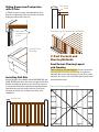
1. Fastening and Trim
Techniques
Pinning Deck Boards
PINNING simply means using a screw to securely
fasten each deck board to a joist at or near the
center of your deck (specific locations detailed on
pages 8 and 9).
ALL DECK BOARDS MUST BE PINNED. This forces any
thermal expansion toward the edge of your deck and
into the G-Trim where the movement can be hidden
from view.
Patented Quick Clip Fasteners
QUICK CLIPS are both spacer and fastener. They
make it simple to install your deck boards with
craftsman-like precision. Each T-shaped clip is
fastened with a screw at every joist along the length
of your deck boards holding them in place while
allowing each board to expand and contract.
The Proper Way to Tighten
a Quick Clip
IT IS VERY IMPORTANT NOT TO OVERTIGHTEN SCREWS.
Quick Clips should be tightened just to the point
where the clip seats to the joist. Overtightening
could lead to fastener failure (deck board lip could
bow or eventually crack).
READ BEFORE YOU START
Pinning to Ledger Joist Pinning to Joists
Tightened Correctly Overtightened
4

2. Post Pockets and
Bracing Methods
Post Pocket / Bracing Layout
and Framing
POST POCKETS ARE MANDATORY. Proper layout and
framing of Post Pockets and Bracing is required to
maintain the structural integrity of your deck, posts
and rails. See other side for detailed post pocket and
bracing instructions.
Hiding Expansion/Contraction
with G-Trim
G-TRIM is a grooved edge trim that allows deck
boards to expand and contract inside the groove
hiding any movement from view.
Installing Rail Kits
Edeck Rail Kits are available in both DECORATIVE and
CODE-COMPLIANT kits. You must use approved Edeck
Rail Kit installation guidelines to ensure the desired
result and avoid thermal expansion related problems
(detailed instructions inside each kit). Determine
the type of rail kit you need based on local code
compliance.
Deck Board
overhang into
G-Trim
Finished G-Trim
Deck Edge
Rail Section
Connection
Detail
Continuous Top-of-Post Rail NOT APPROVED
Basic Post Pocket and Bracing Layout
5

To get the most from your new Edeck composite
building system, please read through these
instructions carefully before you begin. Important
Edeck-specific steps are highlighted in yellow.
Edecks are built on a standard code-compliant wood
frame with a few required additions. Make sure your
deck frame is square.
Because Edeck is a floating system that allows for
expansion/contraction, cross-bracing and blocking are
required for stability (Decks more than 30˝ above
the ground or where local building code requires,
must have cross-bracing).
1. FRAMING
90º Decking: Joists 16˝ center to center 45º Decking: Joists 12˝ center to center
Joist Spacing
Post Pocket
layout for
45º Corners
1b
1c
16˝
12˝
2 Posts required
for each 45º corner
Posts 72˝
maximum
center to
center
Post Pocket Layout
and Bracing
Corner Post Pocket
Line Post
Pocket
B. Rim-Blocking every
16˝ center to center
C. Staggered-Blocking
every 8´ or midway between
spans less than 16´
1a
Rim Joist
Ledger Board
attached to house
A. Diagonal metal/
wood Cross-Bracing
90º
45º
A. Diagonal metal (Simpson Steel Strapping) or
wood (1x4) Cross-Bracing, should be screwed to the
underside of the frame at every joist (Check local
codes for acceptable materials).
B. Install repetitive Rim-Blocking every 16˝ center to
center between the rim joist and neighboring joist.
C. Joists require Staggered-Blocking every 8´ or midway
between spans less than 16´ (measured from house).
Framing in post pockets is the next step. Start by
mapping out pockets
(shown in illustration 1a).
6

Frame in Corner Post Pockets first, then evenly
space and frame in Line Post Pockets (Illustration 1d).
Use a Post as a template when framing Post Pockets
to ensure proper hole dimension. To work with
handrail kit sections, the maximum distance between
posts is 72˝ center to center.
Install Post Pocket Bottoms
(Illustration 1e). Use
scrap lumber to keep post heights level and keep
insects out. Now you are ready to slip Posts into Post
Pockets and secure (illustrations 1e - 1f).
POST POCKETS
Note: POST POCKETS ARE MANDATORY.
Post Holes 4
9
/16˝ sq.
(Use post as
template)
Post Holes 4
9
/16˝ sq.
(Use post as template)
Use construction site
scrap to make post
pocket bottoms.
CORNER POST
POCKET
LINE POST POCKET
INTERRUPTED JOIST
LINE POST POCKET
Post Pocket Types
Post Pocket Bottoms
Fastening Posts into Post Pockets
Drill
5
/16˝ diameter holes through joists and posts (A
metal bit is required when using steel reinforcing). Drill
rim joist hole slightly larger to countersink bolt head.
Use two
5
/16˝ diameter x 8˝ carriage bolts with nuts
and
5
/16˝ x
3
/4˝ diameter washers to fasten Line Posts.
Corner Posts require three carriage bolts, bolting on
both sides of post as shown in illustration to left.
View from under frame
Post Pocket
Bottom
Post Holes 4
9
/16˝ sq.
(Use post as template)
1d
1e
1f
Rim Joist
Post Pocket
Frame
Steel Reinforcing
Tube
Post Carriage Bolts Countersunk Bolt Heads
7

2. DECK BOARD INSTALLATION
Installing Edeck correctly is important. The keys to
success are understanding Pinning and proper use of
our Quick Clip fastener.
PINNING is very important. It directs thermal
expansion toward the edge of your deck, into the
G-Trim (Illustration 3a).
QUICK CLIPS are both spacer and fastener. They make
it simple to install deck boards with craftsman-like
precision while allowing for expansion/contraction.
Important: DO NOT OVERTIGHTEN SCREWS
(Illus. 2a).
Start by Pinning first deck board to the Ledger Board
against house
(Illustration 2a). Plug holes. Install
Quick Clip at each joist. Pin next deck board (Illus. 2c).
Refer to pinning patterns (illus. 2b). Install Quick Clips.
Repeat process until all deck boards are installed.
Leave a minimum
3
/4˝ overhang at both ends of the
deck to allow for an even trim cut after all decking is
installed (Illustration 2b, 2d).
When installing Decking around Posts, on length sides
leave a
3
/4˝ gap to allow for expansion/contraction. On
width sides leave a
1
/8˝ gap (Illustration 3c). Gaps will
be concealed by Post Skirt. Be sure to install skirts
before fastening rail brackets to post.
When all your deck boards are secured, it’s time to
even up your deck board overhang
(Illus. 2b, 2d, 3a).
3. Once all deck boards are installed, go back and
finish tightening Quick Clips just to the point where
clips seat to joist (DO NOT OVERTIGHTEN).
Pinning of first Deck Board against
house and Quick Clip installation steps
House
Screw plug
Ledger Board
2. Loosely screw Quick Clip to
joist allowing enough play for
next deck board to slide in easily
2a
1. On first board, drill a
3
/8˝
hole (through top surface
only) and use self tapping
screws to pin first board
to Ledger (Pattern illus. 2b)
covering hole with plug
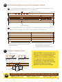
Deck Board Pinning Patterns for various Deck Lengths
2b
24˝24˝ Ledger Board Pinning
Center of Deck
8

24˝24˝
4˝
Deck Board Pinning Patterns for various Deck Lengths continued
2b
2d
TEMPERATURE CHART for determining deck board overhang (illus. 3a)
VERY IMPORTANT: Trim deck boards at the
same time to an even overhang length. Since
temperature is a key factor in expansion
and contraction of composite materials, use
the temperature chart (2d) to determine
the appropriate overhang length based on
the air temperature at the time of trimming.
Trimming all deck boards using these
guidelines is the best way to avoid gaps.
Pinning Deck Boards to Joists
2c
Predrill hole first
Butt Joint Pinning
2˝ x 2˝
2˝ x 2˝
Joist
Quick Clips
Deck board
35° F or 2° C =
1
/4˝ 75° F or 24° C =
1
/2˝ 110° F or 43° C =
3
/4˝
9

3
/
4
˝ Expansion Gap
on both deck-board-
length sides of post
1
/8˝ Expansion Gap
on both deck-board-
width sides of post
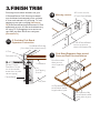
3. FINISH TRIM
First step is to measure and miter cut your
G-Trim and Fascia. Fit G-Trim’s open channel
over deck board overhang and secure to frame
4˝ from each end and every 16˝ using 1
1
/4˝ self
tapping screws and screw plug (Illustration
3a). Butt Fascia Board up to bottom of G-Trim
and attach to joist 4˝ from each end and every
16˝ using 1
1
/4˝ self tapping screws and screw
cap. Slide your Post Skirts over each post
(Illustration 3c).
45º corner cuts for
G-Trim & Fascia Board
Mitering corners
3b
G-Trim & Fascia Board
secures to joist as
shown in illustration 3a
3c
Deck Board Expansion Gaps around
Posts and Post Skirt installation
Post Skirt slides
down post to
cover expansion
gaps
G-Trim hides Deck Board
Expansion /Contraction
G-Trim
3a
Deck Board
Rim Joist
Fascia Board
Deck Board Overhang
(See chart 2d for measurement)
(Butt G-Trim to
Stair Riser. Do not
use in foot-traffic
areas where it could
cause tripping.)
1
1
/4˝
Self Tapping
Screws
Drilled
3
/8˝ hole

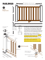
The final step is to assemble and install your Rail
Kits. Measure each rail section from post to post
and cut railings to size allowing
1
/16˝ gap at each
end. Make sure to cut equal sections from both
ends so balusters will be evenly spaced. Attach Rail
Brackets to Post. Fasten Midrail Support Bracket
and Footing to center of bottom rail. Insert
Balusters into railings. Guide assembled section
into brackets and fasten with screws (Do not
overtighten to allow for Expansion). Screw Post
Caps to post and your deck is ready to show off.
You’ll find more complete detailed assembly
instructions inside each Rail Kit box.
OBTAIN FINAL INSPECTION WHEN REQUIRED.
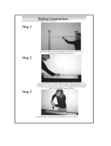
RAILINGS
72˝ maximum center to center
36˝
1
/
16
˝ Expansion Gap both ends top and bottom rails
Post Caps sold
separately
Rail Kit
Requirements
Rail Kit Assembly
3d
Check local
codes for deck
heights that
require railings
Midrail support to
prevent sagging
3e
Baluster
Railing
Rail
Bracket
Midrail Footing Bracket
Midrail Footing
Midrail Footing
2
1
/4˝ Screws
1˝ Screws
11
-
 1
1
-
 2
2
-
 3
3
-
 4
4
-
 5
5
-
 6
6
-
 7
7
-
 8
8
-
 9
9
-
 10
10
-
 11
11


EDECK EASY AS 3 Installation guide
- Type
- Installation guide
Ask a question and I''ll find the answer in the document
Finding information in a document is now easier with AI
Other documents
-
FMI FT26 Operating instructions
-
Severe Weather 1255878 Installation guide
-
Deckorators 346942 Installation guide
-
Weatherables LBAL-POSTKIT-2.5X54A Installation guide
-
Simpson Strong-Tie EB332WDR175 Installation guide
-
Freedom 73024624 User manual
-
Deckorators 398872 Installation guide
-
-
-
 Pegatha 50020006 Installation guide
