Page is loading ...

3M
™
Glass Bubbles
Bag Unloading Suggestions
3M Advanced Materials Division
Introduction
This guide provides suggestions for the
efficient removal of 3M
™
Glass Bubbles from
bulk bags (FIBC—Flexible Intermediate
Bulk Containers). These are not intended
for use as a design specification or
operational manual. The user is responsible
for determining the method and equipment
appropriate for the user’s operation.
Note: Refer to the Product Label and Safety
Data Sheet (SDS) for Product Health and
Safety Information on glass bubbles.
Refer to the glass bubbles Product Data
Sheet for additional storage and handling
information. See the appendix for equipment
and component considerations.
Bulk Bag
3M glass bubbles are available in
approximately 50 cubic foot (1.41 cubic
meter) bulk bags with a polyethylene liner
and ten-inch bag lifting loops. The liner has
a 22 in (0.56m) diameter by 30 in. (.762m)
long discharge spout in the base. The filled
bag size is approximately 45 in W × 45 in L
× 46 in H (1.14m × 1.14m × 1.17m). Bags are
stacked two per pallet then wrapped with a
stretch film. The maximum shipped height is
104 in (2.64m). The pallet is a two-way entry
type. Typical shipping is in a “high cube”
trailer or a 40 foot “high cube” seagoing
shipping container. Bags are not returnable.
Note: The purpose of this guide is to provide basic information to product users for use in evaluating, processing, and troubleshooting their use of certain 3M
products. The information provided is general or summary in nature and is offered to assist the user. The information is not intended to replace the user’s
careful consideration of the unique circumstances and conditions involved in its use and processing of 3M products. The user is responsible for determining
whether this information is suitable and appropriate for the user’s particular use and intended application. The user is solely responsible for evaluating third party
intellectual property rights and for ensuring that user’s use and intended application of 3M product does not violate any third party intellectual property rights.
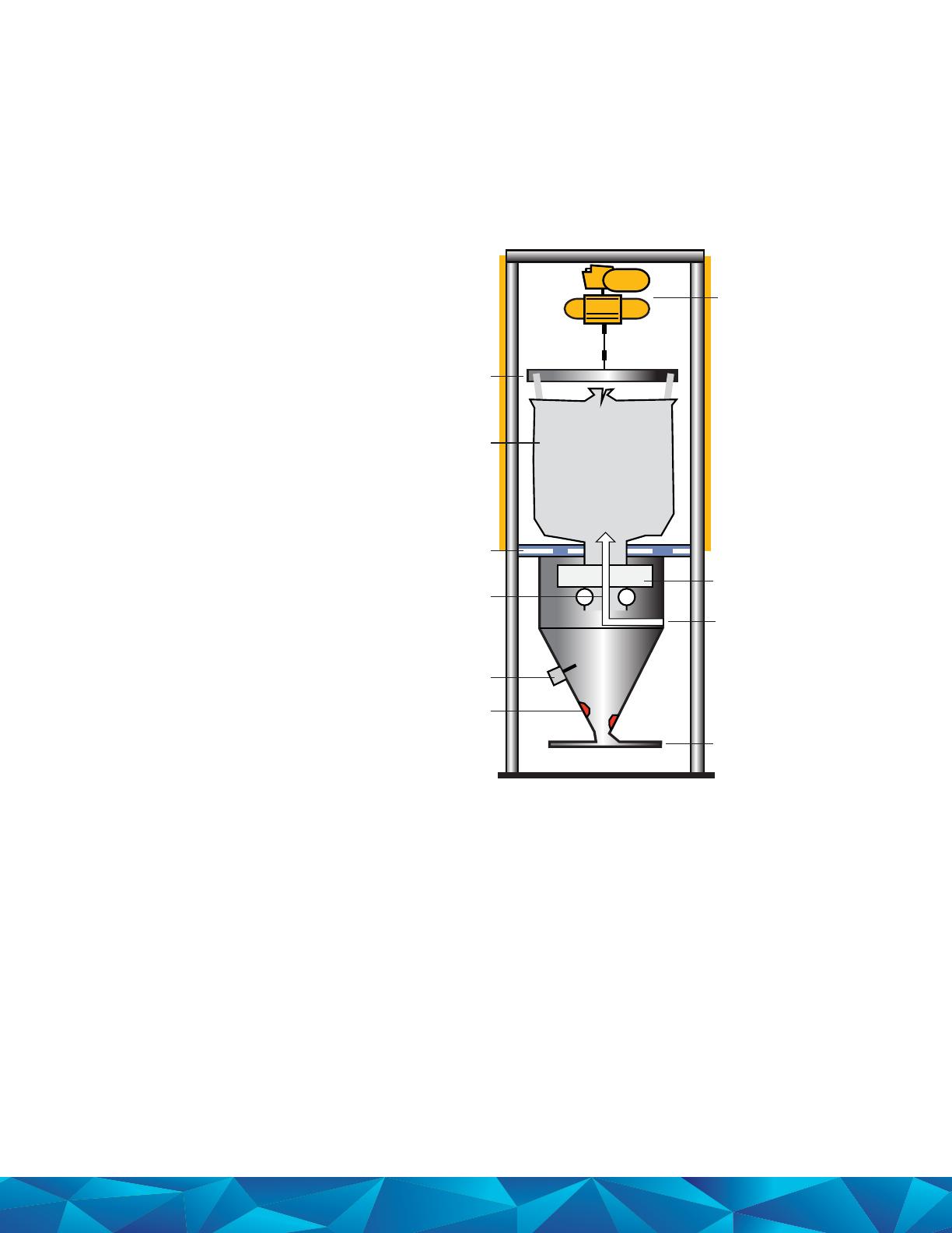
Discharge
to process
Trolley
hoist
Lift frame
Bulk bag
Flexible
cover
Window
Level sensor
Glove box
Fluidizers
Air lance
Bag Unloading Suggestions
Bulk Bag Discharging
Typically, bulk bags are suspended in
an unloading station. Material is usually
transferred by vacuum suction from a
vacuum receiver or a double-diaphragm
pneumatic pump. Material is pulled through
the conveying line, either for a predetermined
time or until a desired weight is reached
in the stand or the receiving vessel. Using
valves the system can supply material to
one or more processes. Filters separate air
from the material in the receiving vessel. The
filter is cleaned with pulsed, high-pressure,
conditioned, dry air. Dust collection trunks or
hoods are usually placed near the system.
Bulk Bag Station
Bulk bags require a lifting frame for
handling the bags safely. The lifting
frame can be attached to an overhead
trolley or placed on a forklift truck.
Do not use clamp forklifts for moving glass
bubble-filled bulk bags as they may cause
bubble breakage or release bubbles into the air.
The most dust-free method of discharging
bulk bags is to place the bag into a bag
unloading station. The station includes a
glove box hopper with a window, light and
flexible dust containment cover. The flexible
hopper top is slightly stretched by the bag
weight in order to minimize dust when the
bag discharge spout is opened. The station
can be enclosed on three sides. Usually,
dust collection vents are placed above the
top of the hopper. Dry air is used to fluidize
material in the hopper. If desired the station
can include a weigh cell system for metering
material to the process by weight. Capacitance
sensors are used to detect material level.
Often for mix tanks the bulk bag is discharged
directly into the entry way of the vessel. This
requires an auxiliary filter port in order to
collect the dust created during bag discharging.

Site tube
Hopper
Vent per
requirements
Pinch valve
Reverse pulsed
lter
Dump valve
Mixer/Process
Filter
Blower
Air assist
From storage
Air pad
To process
Site tube
Pump
From storage
Suction
relief
Bleed down
Bag Unloading Suggestions
Vacuum Conveying
The vacuum transport system is a pull-only
conveying system. The pull system operates
at a negative pressure, below atmospheric. It
may use a venturi, two-stage fan or a positive
displacement blower (illustrated) to move the
air that carries the material. The vacuum system
will move material at higher line velocities
than the pump system. The advantage is that
it does not leak particles into the work area.
This system is not prone to line plugging
problems. The primary filter is usually cleaned
with pulsed, high-pressure, clean, dry air. A
secondary filter is placed after the receiver
filter in order to protect the fan or blower.
An adjustable vacuum relief valve regulates
vacuum in the receiver. Typical suction is
50 to 100 inches of water column. A hopper
sight panel and cone aeration is suggested.
Double Diaphragm Pump
Typically, a three-inch pneumatic double-
diaphragm pump is used to move lightweight
powders. It is a lower cost method that
effectively transfers aerateable low bulk
density powders. The air-driven pump is a
combination pull/push, vacuum-pressure
conveying system. The pump pulls material
by vacuum into its inlet, then pushes the
material along the conveying line with
pressure. In the pressure conveying system
poor line connections will leak dust into
the workplace. The pump should be placed
closer to the process rather than near
the box in order to pull material a longer
distance. This will reduce line plugging.
Purge air added into a pump chamber when
it is pushing material into the line helps to
decrease pump plugging and stalling. Often
a vacuum relief valve is mounted close to
the pump suction port. A bleed down valve
at the pump outlet is suggested for relieving
pressure from a plugged line or pump. Purging
of the pump and the conveying system with
air or other compatible gas is suggested
before and after glass bubble transfer.
Conveying Lines and Hoses
Conveying lines connect the various system
components for glass bubble handling.
Typically, a transfer system uses 3-in
(76mm) components. Glass bubbles should
be transferred with a line velocity of less
than 1200 ft/min (300 m/min). Lines with
long radius bends or sweeps are suggested
instead of ninety degree elbows.
Lines can be combinations of rigid and
flexible materials. All conveying lines and all
components should be electrically grounded.
Hoses with a smooth inner bore and a
conductive drain wire are suggested. The drain
wire must be connected to metal connectors.
Flexible lines may range from braided chemical
hose, semitransparent PVC, clear polyurethane
to interlocking metal hose. Be careful, however,
as some hoses are limited to use above 20°F.
Flow Aids
Air assists in the conveying line are used
to keep conveying lines trouble-free. They
are typically mounted at the bottom of
vertical line legs and about every fifty feet in
horizontal line runs. Air pads mounted near
the discharge port in hoppers are suggested
to help fluidize material for easy transfer.
Sight Windows and
Sight Tubes
Sight windows and sight tubes are a big aid
to observe material flow in order to locate a
problem in the transfer system. Suggested
mounting locations are at the pump outlet or
the bottom of vertical legs, or optionally at
the receiving vessel entrance. Sight tubes use
Pyrex glass or transparent PVC schedule 80
tubing. Grounding with a wire across the length
of the sight tube is suggested. Polycarbonate
material is suggested for windows.

3M Advanced Materials Division
3M Center
St. Paul, MN 55144 USA
Phone 1-800-367-8905
Web www.3M.com/glassbubbles
3M is a trademark of 3M Company.
Used under license by 3M subsidiaries
and affiliates.
Please recycle. Printed in USA. © 3M 2015.
All rights reserved. Issued: 12/16 11607HB
98-0212-2477-3 rev B
Warranty, Limited Remedy, and Disclaimer: Many factors beyond 3M’s control and uniquely within user’s knowledge and control can affect the use
and performance of a 3M product in a particular application. User is solely responsible for evaluating the 3M product and determining whether it is fit
for a particular purpose and suitable for user’s method of application. User is solely responsible for evaluating third party intellectual property rights
and for ensuring that user’s use of 3M product does not violate any third party intellectual property rights. Unless a different warranty is specifically
stated in the applicable product literature or packaging insert, 3M warrants that each 3M product meets the applicable 3M product specification at
the time 3M ships the product. 3M MAKES NO OTHER WARRANTIES OR CONDITIONS, EXPRESS OR IMPLIED, INCLUDING, BUT NOT LIMITED
TO, ANY IMPLIED WARRANTY OR CONDITION OF MERCHANTABILITY OR FITNESS FOR A PARTICULAR PURPOSE OR ANY IMPLIED WARRANTY
OF NON-INFRINGEMENT OR ANY IMPLIED WARRANTY OR CONDITION ARISING OUT OF A COURSE OF DEALING, CUSTOM OR USAGE OF
TRADE. If the 3M product does not conform to this warranty, then the sole and exclusive remedy is, at 3M’s option, replacement of the 3M product or
refund of the purchase price.
Limitation of Liability: Except where prohibited by law, 3M will not be liable for any loss or damages arising from the 3M product, whether direct,
indirect, special, incidental or consequential, regardless of the legal theory asserted, including warranty, contract, negligence or strict liability.
Technical Information: Technical information, recommendations, and other statements contained in this document or provided by 3M personnel are
based on tests or experience that 3M believes are reliable, but the accuracy or completeness of such information is not guaranteed. Such information
is intended for persons with knowledge and technical skills sufficient to assess and apply their own informed judgment to the information. No license
under any 3M or third party intellectual property rights is granted or implied with this information.
Appendix: Equipment Manufacturers
The following equipment manufacturers are identified for your convenience. 3M makes no
representations about the manufacturer or their equipment. The user is responsible for determining
what method and equipment are fit for a particular purpose and suitable for the user’s application.
Systems
Nol-Tec Systems, Inc.
425 Apollo Drive
Lino Lakes, MN 55014
Phone: 651-780-8600
Web: www.nol-tec.com
Bulk Bag Unloading
Custom Equipment Design
1057 Highway 80 East
Monroe, LA 71203
Phone: 318-345-2222
Control & Metering
6500 Kestrel Road
Mississauga, ONT L5T 1Z6
Phone: 800-736-5739
Website:
www.controlandmetering.com
Components
McMaster-Carr Supply Company
600 County Line Road
Elmhurst, IL 60126-2081
Phone: 800-990-7867
Website:
www.mcmastercarr.com
Morris Coupling Company
2240 West 15th Street
Erie, PA 16505
Phone: 800-426-1579
Website:
www.morriscoupling.com
Sight Tube
Harvel Plastics, Inc.
P.O. Box 757
Easton, PA 18044-0757
Phone: 610-252-7355
Website: www.harvel.com
Flow Aids
Solimar Pneumatics
7256 Commerce Circle
Minneapolis, MN 55432
Phone: 800-233-7109
Website:
www.solimarpneumatics.com
Porex Industries
500 Bohannon Road
Fairburn, GA 30213
Phone: 770-964-1421
Website: www.porex.com
Double Diaphragm Pumps
Ingersol Rand Fluid Products
P.O. Box 151
Bryan, OH 43506
Phone: 419-636-4242
Website: www.arozone.com
Yamada America
1200 Nuclear Drive
West Chicago, IL 60185
Phone: 800-990-7867
Website:
www.yamadapump.com
Wilden Pump & Engineering Co.
22069 Van Buren Street
Grand Terrace, CA 92313-5607
Phone: 909-422-1730
Website: www.wilden.com
Resources
For further information or sales
assistance, please contact:
3M Advanced Materials
Phone: 800 367 8905 Fax: 800 81 8514
/