Kenmore 721.80822500 Owner's manual
- Category
- Microwaves
- Type
- Owner's manual
This manual is also suitable for

DIVISION 22
BASIC FIELD MANUAL
FOR
MICROWAVE HOOD COMBINATION
MODEL
721.80822500
721.80823500
721.80824500
721.80829500
May, 2005
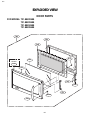
MODEL 721.80822
721.80823
721.80824
721.80829

CAUTION
WARNING TO SERVICE TECHNICIANS
PRECAUTIONS TO BE OBSERVED BEFORE AND
DURING SERVICING TO AVOID POSSIBLE EXPOSURE
TO EXCESSIVE MICROWAVE ENERGY
a. Do not operate or allow the oven to be operated with the door open.
b. Make the following safety checks on all ovens to be serviced before activating the
magnetron or other microwave source, and make repairs as necessary; (1) Interlock
operation, (2) proper door closing, (3) seal and sealing surfaces (arcing, wear, and other
damage), (4) damage to or loosening of hinges and latches, (5) evidence of dropping or
abuse.
c. Before turning on microwave power for any service test or inspection within the
microwave generating compartments, check the magnetron, wave guide or
transmission line, and cavity for proper alignment, integrity, and connections.
d. Any defective or misadjusted components in the interlock, monitor, door seal, and
microwave generation and transmission systems shall be repaired, replaced, or
adjusted by procedures described in this manual before the oven is released to the
owner.
e. A Microwave leakage check to verify compliance with the Federal performance
standard should be performed on each oven prior to release to the owner.
• Proper operation of the microwave ovens requires that the magnetron be assembled to the wave guide and cavity.
Never operate the magnetron unless it is properly installed.
• Be sure that the magnetron gasket is properly installed around the dome of the tube whenever installing the
magnetron.
• Routine service safety procedures should be exercised at all times.
• Untrained personnel should not attempt service without a thorough review of the test procedures and safety
information contained in this manual.

FOREWORD
Read this Manual carefully. Failure to adhere to or observe the information in this Manual may result in exposing
yourself to the Microwave Energy normally contained within the oven cavity.
MODEL 721.80822
721.80823
721.80824
721.80829
TABLE OF CONTENTS
(Page)
SAFETY PRECAUTIONS ................................................................................................................Inside front page
SPECIFICATIONS................................................................................................................................................ 1-1
CAUTIONS ........................................................................................................................................................... 2-1
INSTALLATIONS.................................................................................................................................................. 3-1
OPERATING INSTRUCTIONS............................................................................................................................. 4-1
CONTROL PANEL ............................................................................................................................................... 4-1
CONTROL PANEL INSTRUCTIONS.................................................................................................................... 4-2
OVERALL CIRCUIT DIAGRAM............................................................................................................................ 5-1
SCHEMATIC DIAGRAM....................................................................................................................................... 5-1
MATRIX CIRCUIT FOR TOUCH KEY BOARD .................................................................................................... 5-2
GENERAL INFORMATION FOR SERVICE ......................................................................................................... 6-1
GENERAL PRECAUTIONS IN USE .................................................................................................................... 6-1
TRIAL OPERATION ............................................................................................................................................. 6-1
FEATURES AND SPECIFICATIONS FEATURES............................................................................................... 6-1
SERVICE INFORMATION.................................................................................................................................... 7-1
PRECAUTIONS AND REPAIR SERVICE TIPS ................................................................................................... 7-1
MICROWAVE LEAKAGE TEST ........................................................................................................................... 7-2
POWER OUTPUT MEASUREMENT.................................................................................................................... 7-3
DISASSEMBLY INSTRUCTIONS ........................................................................................................................ 7-4
INTERLOCK SYSTEM ....................................................................................................................................... 7-12
INTERLOCK CONTINUITY TEST ...................................................................................................................... 7-14
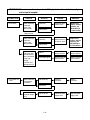
TEST AND CHECKOUT PROCEDURES AND TROUBLESHOOTING............................................................. 7-15
A. TEST PROCEDURES.................................................................................................................................... 7-15
B. CHECKOUT PROCEDURES......................................................................................................................... 7-20
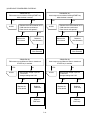
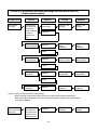
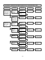
C. TROUBLESHOOTING ................................................................................................................................... 7-23
EXPLODED VIEW ................................................................................................................................................ 8-1
REPLACEMENT PARTS LIST ............................................................................................................................. 9-1

1-1
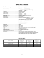
SPECIFICATIONS
Rated Power Consumption ................................Microwave 1600W
Convection 1700W
Microwave Output ...............................................Microwave 950W (IEC60705)
Adjustable 95W through 950W, 10 steps
Convection 1500W
Frequency ..........................................................2450 MHz ±50 MHz
Power Supply .....................................................120 VAC, 60 Hz
Rated Current ....................................................Microwave 13.5A
Convection 14.0A
Magnetron Cooling .............................................Forced Air Cooling
Rectification .......................................................Rectification Voltage Double Half-Wave
Door Sealing ......................................................Choke System
Safety Devices ...................................................Magnetron Thermostat: Open at 150 °C ± 5 °C
Close at 0 °C ± 5 °C
............................................................................Oven Thermostat: Open at 145 °C ± 5 °C
Close at 0 °C ± 5 °C
............................................................................Fuse(20A)
............................................................................Primary Interlock Switch
............................................................................Secondary Interlock Switch
............................................................................Interlock Monitor Switch
Magnetron ..........................................................2M246
Cook top Lamp ...................................................130 V, 35 W
Cavity Lamp .......................................................130 V, 35 W
Timer ..................................................................Digital, up to 99 min. 99 sec. (in each cooking stage)
Tray ....................................................................Tempered Safety Glass
Overall Dimensions ............................................29
15
/16”(W)x16
7
/16”(H)x15
3
/8”(D)
Oven Cavity Size ...............................................21
1
/4”(W)x9
7
/16”(H)x14
3
/16”(D)
Effective Capacity of Oven Cavity ......................1.7 Cu.ft.
Accessories ........................................................Use & Care Guide, Cooking Guide, Installation Manual
Exhaust Adapter, Exhaust Damper, Mounting Kit & Two Filter
Shaft, Rotating Ring, Glass Tray, Grill Rack, Metal Tray
SWITCH CHART
SWITCH MODE
CONDITIONS
DOOR OPEN
OPEN OPEN CLOSE
CLOSE CLOSE OPEN
DOOR CLOSED
PRIMARY
INTERLOCK
SWITCH
SECONDARY
INTERLOCK
SWITCH
INTERLOCK
MONITOR
SWITCH
COM
NO
COM
NO
COM
NC
NOTE: Use the above switch chart with circuit diagram on page 5-1.

2-1
CAUTIONS
Unlike other appliances, the microwave oven is
high-voltage and high-current equipment.
Though it is free from danger in ordinary use,
extreme care should be taken during repair.
MICROWAVE RADIATION
Personnel should not be exposed to the
microwave energy which may radiate from the
magnetron or other microwave generating
device if it is improperly used or connection.
All input and output microwave connections,
waveguide, flange, and gasket must be secure
never operate the device without a microwave
energy absorbing load attached.
Never look into an open waveguide or antenna
while the device is energized.
• DO NOT operate on a 2-wire extension cord during repair
and use.
• NEVER TOUCH any oven components or wiring during
operation.
• BEFORE TOUCHING any parts of the oven, always
remove the power plug from the outlet.
• Remove your watches whenever working close to or
replacing the Magnetron.
• DO NOT touch any parts of the control panel circuit. A
resulting static electric discharge may damage this P.C.B.
• NEVER operate the oven with no load.
• NEVER injure the door seal and front plate of the oven
cavity.
• NEVER put iron tools on the magnetron.
• NEVER put anything into the latch hole and the interlock
switches area.
• Proper operation of the microwave oven requires that
the magnetron be assembled to the waveguide and
cavity. Never operate the magnetron unless it is
properly installed.
• Be sure that the magnetron gasket is properly
installed around the dome of the tube whenever
installing the magnetron.
THE OVEN IS TO BE SERVICED ONLY
BY PROPERLY QUALIFIED SERVICE
PERSONNEL.
Gasket
ANTENNA
COOLING FIN
MAGNETRON
CHASSIS GROUND
FILAMENT
TERMINALS
MAGNETRON

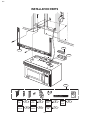
3-1
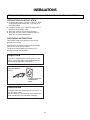
INSTALLATIONS
BEFORE YOU BEGIN, READ THE FOLLOWING INSTRUCTIONS COMPLETELY AND CAREFULLY.
PRECAUTIONS ON INSTALLATION
A. Plug the power supply cord into a 120V AC, 60Hz,
single-phase power source with a capacity of at
least 20 amperes.
B. Avoid placing the unit in a location where there is
direct heat or splashing water.
C. Install the unit on the mounting plate firmly.
D. Place the unit as far away as possible from TV,
radio, etc. to prevent interference.
GROUNDING INSTRUCTIONS
For personal safety, this appliance must be fully
grounded at all times.
In the event of an electrical short circuit, grounding
reduces the risk of electrical shock.
The plug must be plugged into an outlet that is
properly installed and grounded.
CAUTION
This unit is equipped with a 3-prong plug for your
safety. If the wall outlet is a grounded 3-hole type,
the unit will be grounded automatically.
WARNING
Improper use of the grounding plug can result in a
risk of electric shock.
Do not, under any circumstances, cut or remove the
third ground prong from the power cord plug.
Plug with Ground
Prong
Properly Polarized
and Grounded
Outlet

4-1
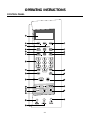
OPERATING INSTRUCTIONS
CONTROL PANEL

4-2
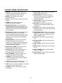
CONTROL PANEL INSTRUCTIONS
1. DISPLAY. The Display includes a clock and
indicators to tell you time of day, cooking time
settings and cooking functions selected.
2. MICRO. Touch this pad when setting
Microwave cooking.
3. CONV. Touch this pad when setting Convection
cooking.
4. COMBI. Touch this pad when setting
combination cooking or preheat.
5. SENSOR POPCORN. Touch this pad when
popping popcorn in your microwave oven. The
oven’s sensor will tell the oven how long to cook
depending on the amount of humidity it detects
from the popcorn.
6. SENSOR COOK. Touch this pad to cook baked
potato, frozen vegetable, fresh vegetable,
canned vegetable, frozen entree and rice. The
oven’s sensor will tell the oven how long to cook
depending on the amount of humidity coming
from the food.
7. SENSOR REHEAT. Touch this pad to reheat
casserole, dinner plate, pizza slice and
soup/sauce. The oven’s sensor will tell the oven
how long to cook depending on the amount of
humidity coming from the food.
8. SPEED AUTO COMBI. Touch this pad when
setting weight combination cooking.
9. AUTO COOK. Touch this pad to cook Bacon,
Fresh Roll & Muffin, Frozen Roll & Muffin,
Beverage, Chicken Pieces, Hot Cereal.
10. AUTO DEFROST. Touch this pad to select
food type and defrost food by weight.
11. NUMBER. Touch number pads to enter
cooking time, power level, quantities, weights,
or cooking temperature.
12. SOFTEN. Touch this pad to soften Butter , Ice
Cream, Cream Cheese or Frozen Juice.
13. MELT. Touch this pad to melt Butter or Margarine
Chocolate, Cheese, Marshmallow.
14. POWER. Touch this pad to select a cooking
power level.
15. ADD 30 SEC. Touch this pad to set and start
quickly at 100% power level.
16. START/ENTER. Touch this pad to start a
function or enter all entries. If you open the
door after oven begins to cook, touch
START/ENTER again.
17. STOP/CLEAR. Touch this pad to stop the
oven or to clear all entries.
18. FAVORITE. Touch this pad to recall one
cooking instruction previously programmed
into memory.
19. OPTION. Touch this pad to change the oven’s
default settings for sound, clock, display speed
and defrost weight.
20. TURNTABLE ON/OFF. Touch this pad to turn
off the turntable. OFF will appear in the display.
NOTE: This option is not available in sensor
cook and defrost modes.
21. CLOCK. Touch this pad to enter the time of
day.
22. KITCHEN TIMER. Touch this pad to set the
kitchen timer.
23. LIGHT TIMER. Touch this pad to set the light
timer.
24. VENT ON/OFF. Touch this pad to turn the fan
on/ off.
25. VENT 5-SPEED. Touch this pad to choose
one of 5 fan speeds.
26. LIGHT ON/OFF. Touch this pad to turn on the
cooktop/countertop light.

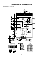
5-1
OVERALL CIRCUIT DIAGRAM
SCHEMATIC DIAGRAM

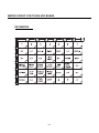
5-2
MATRIX CIRCUIT FOR TOUCH KEY BOARD
KEY MATRIX

6-1
GENERAL INFORMATION FOR SERVICE
GENERAL PRECAUTIONS IN USE
A. Never operate the unit when it is empty.
Operating the oven with no load may shorten the
life of the magnetron. Whenever cooking dry foods
(dried fish, bread, etc.)or a small amount of food,
be sure to put a glass of water into the cooking
compartment. The glass turntable may become hot
after operating, be careful when touching it.
B. Aluminum foil should be avoided because it will
disrupt cooking and may cause arcing. However,
small pieces may be used to cover some parts of
food to slow the cooking. Any aluminum foil used
should never be closer than 2.5 cm to any side wall
of the oven.
TRIAL OPERATION
After installation, the following sequences and results
should be checked carefully.
A. Put a container filled with water (about 1 liter)into
the oven, and close the door tightly.
B. Set cooking time for 10 minutes by touching “1 ”
and then “0” three times.“1, 0, 0, 0” appears in the
display window.
C. Touch the START key.
Make sure the cavity light comes on. The unit will
begin cooking and the display window will show the
time counting down by seconds.
D. After about 5 minutes, make sure the primary
interlock switch, the secondary interlock switch and
the interlock monitor switch operate properly by
opening and closing the door several times. Touch
the START key each time the door is closed.
E. Continue operating the unit. Two short and a long
beep sound signal is heard when the time is up.
The unit will shut off automatically.
F. Confirm the water is hot.
G. Finally, measure the output power according to
“POWER OUTPUT MEASUREMENT” on
page 7-3.
FEATURES AND SPECIFICATIONS
FEATURES
A. The safety systems incorporated in this model are:
(1) Primary interlock switch
(2) Secondary interlock switch
(3) Interlock monitor switch
(4) Choke system
(5) Oven cavity thermostat
(Note This thermostat located on the oven cavity
will open and stop the unit from operation only if
a high temperature is reached, such as, a fire
created by overcooking food.)
B. Any one of 10 power output levels ranging 0W to
950W can be selected by the touch control and
electronic computer system.
C. Cooking time can be displayed on the digital
readout.
D. Three different cooking stages (Include Defrost)
can be changes from one cooking stage to another.
This is made possible with the memory function of
the microprocessor.

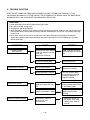
7-1
SERVICE INFORMATION
PRELIMINARY
A. SINCE NEARLY 4000 VOLTS EXISTS IN SOME
CIRCUITS OF THIS UNIT REPAIRS SHOULD BE
CARRIED OUT WITH GREAT CARE.
The filament leads of magnetron carry High
Voltage with respect to ground. Extreme caution
must be exercised. Never plug the unit into a
power source to determine which component is
defective in high voltage section.
B. TO AVOID POSSIBLE EXPOSURE TO
MICROWAVE ENERGY LEAKAGE, THE
FOLLOWING PRECAUTIONS MUST BE TAKEN
BEFORE SERVICING.
(1) Before the power is applied:
(a) Make sure the primary interlock switch, the
secondary interlock switch and the interlock
monitor switch operate properly by opening
and closing the door several by opening and
closing the door several times.
(b) Make sure the perforated screen and the
dielectric choke of the door are correctly and
firmly mounted.
(2) After power is applied:
(a) Make sure the interlock switch mechanism
is operating properly by opening and closing
the door.
(b)
Check microwave energy leakage must be below
the limit of 5 mW/cm
2
.
(All service adjustments should be made for
minimum microwave energy leakage
readings).
(3) Do not operate the unit until it is completely
repaired, if any of the following conditions exist.
The unit must not be operated.
(a) The door does not close firmly.
(b) The hinge is broken.
(c) The door seal is damaged.
(d) The door is bent or warped, or there is any
other visible damage on the unit that may
cause microwave energy leakage.
NOTE: Always keep the seal clean.
(e) Make sure that there are no defective parts
in the interlock mechanism.
(f) Make sure that there are no detective parts
in the microwave generating and transmission
assembly (especially waveguide).
(4) The following items should be checked after the
unit is repaired:
(a) The interlock monitor switch is connected
correctly and firmly.
(b) The magnetron gasket is properly positioned
and mounted.
(c) The waveguide and the oven cavity are intact.
(no microwave energy leakage)
(d) The door can be properly closed and the
safety switches work properly.
(e) The unit must stop when the door is opened or
the time is up.
The unit must not be operated with any of the above
components removed or by-passed.
PRECAUTIONS AND REPAIR SERVICE TIPS

7-2
MICROWAVE LEAKAGE TEST
CAUTIONS
• Be sure to check microwave leakage prior to
servicing the oven if the oven is operative prior to
servicing.
• The service personnel should inform the
manufacture importer, or assembler of any certified
oven unit found to have a microwave emission level
in excess of 5 mW/cm
2
and should repair any unit
found to have excessive emission levels at no cost to
the owner and should ascertain the cause of the
excessive leakage. The service personnel should
instruct the owner not to use the unit until the oven has
been brought into compliance.
• If the oven operates with the door open, the service
personnel should;
- Tell the user not to operate the oven
- Contact the manufacturer and CDRH (Center for
Devices and Radiological Health)immediately.
NOTE: Address on CDRH
Office of Compliance (HFZ-312)
Center for Devices and Radiological Health
1390 Piccard Drive Rockville, Maryland 20850
• The service personnel should check all surface and
vent openings for microwave emission testing.
• Check for microwave energy leakage after every
servicing. The power density of the microwave
radiation leakage emitted by the microwave oven
should not exceed 1mW/cm.sq. And always start
measuring of an unknown field to assure safety for
operating personnel from radiation leakage.
NOTE: The standard is 5mW/cm.sq. while in the
customer’s home.1mW/cm.sq.stated here is
manufacturer’s own voluntary standard for units in
customer ’s home.
EQUIPMENT-
• TESTER ((VOLTS-DC, AC, Ohmmeter)
• Microwave survey meter
- Holaday HI-1500
HI-1501
- Narda 8100
8200
• 600 cc non conductive material beaker (glass or
plastic), inside diameter:approx.8.5 cm (3
1
/
2 in.)
• Glass thermometer: 100 °C or 212 °F (1 deg scale)
MEASURING MICROWAVE ENERGY
LEAKAGE
• Pour 275±15cc of 20±5°C(68±9°F) water in a beaker
which is graduated to 600 cc, and place the beaker
on the oven.
• Set the energy leakage monitor to 2,450 MHz and
use it following the manufacturer's recommended
test procedure to assure correct result.
• When measuring the leakage, always use the 2-inch
(5cm) spacer supplied with the probe.
• Operate the oven at its maximum output.
• Measure the microwave radiation using and
electromagnetic radiation monitor by holding the
probe perpendicular to the surface being measured.
Move probe along shaded area.
Probe scanning speed
Less than 2.5 cm/sec. ( 1 in/sec)

7-3
MEASUREMENT WITH THE OUTER CASE
REMOVED
(1) When you replace the magnetron, measure for
microwave energy leakage before the outer case
is installed and after all necessary components
are replaced or adjusted. Special care should be
taken in measuring the following parts.
-Around the magnetron
-The waveguide
WARNING: AVOID CONTACTING ANY HIGH
VOLTAGE PARTS.
MEASUREMENT WITH A FULLY
ASSEMBLED OVEN
(1) After all components, including the outer
panels, are fully assembled, measure for
microwave energy leakage around the door
viewing window, the exhaust opening and air
inlet openings.
(2) Microwave energy leakage must not exceed the
values prescribed below.
NOTES:
Leakage with the outer panels removed -less
than 5 mW/cm
2
.
Leakage for a fully assembled oven (“Before the
latch switch (primary)is interrupted”)with the door
in a slightly opened position -less than 1 mW/cm
2
NOTE WHEN MEASURING
(1) Do not exceed meter full scale deflection.
(2) The test probe must be removed no faster than
1 inch/sec (2.5cm/sec)along the shaded area,
otherwise a false reading may result.
(3) The test probe must be held with the grip portion
of the handle. A false reading may result if the
operator ’s hand is between the handle and the
probe.
(4) When testing near a corner of the door, keep
the probe perpendicular to the surface making
sure the probe horizontally along the oven
surface, this may possibly cause probe damage.
RECORD KEEPING AND NOTIFICATION
AFTER MEASUREMENT
(1) After adjustment and repair of any microwave
energy interruption or microwave energy blocking
device, record the measured values for future
reference. Also enter the information on the
service invoice.
(2) Should the microwave energy leakage not be
more than 1 mW/cm
2
after determining that all
parts are in good condition, functioning properly
and genuine replacement parts which are listed in
this manual have been used.
(3) At least once a year, have the electromagnetic
energy leakage monitor checked for calibration
by its manufacturer.
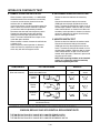
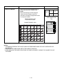
POWER OUTPUT MEASUREMENT
(1) Microwave power output measurement is made
with the microwave oven supplied at its rated voltage and
operated at its maximum microwave power setting with a
load of (1000 ± 5)g of potable water.
(2) The water is contained in a cylindrical borosilicate
glass vessel having a maximum material thickness
of
1
/8” (3 mm)and an outside diameter of approximately
7.6” (190mm).
(3) The oven and the empty vessel are at ambient
Temperature(T0)prior to the start of the test.
(4) The initial temperature (T1)of the water is
(10 ±1)°C (50 °F)It is measured immediately before the
water is added to the vessel. After addition of the water to
the vessel, the load is immediately placed on the center
of the turntable which is in the lowest position and the
microwave power switched on.
(5) The time t for the temperature of the water to rise
by a value T of (10 ±1)°K is measured, where t is the
time in seconds and T is the temperature rise.
The initial and final water temperatures are selected so
that the maximum difference between the final water
temperature and the ambient temperature is 5 °K.
(6) The microwave power output P in watts is calculated
from the following formula :
4,187 Mw(T2 –T1)+0.55Mc(T2 –T0)
t
is measured while the microwave generator is
operating at full power. Magnetron filament heat-up
time is not included. (about 3 sec)
(7) The water is stirred to equalize temperature
throughout the vessel, prior to measuring the final
water temperature.
(8) Stirring devices and measuring instruments are
selected in order to minimize addition or removal of
heat.
P =
Where
P is the microwave power output, in watts:
Mw is the mass of the water, in grams:
Mc is the mass of the container, in grams:
T0 is the ambient temperature, in °C:
T1 is the initial temperature of the water, in °C:
T2 is the final temperature of the water, in °C:
t is the heating time in seconds, excluding the magnetron filament heat-up time.
WATER LOAD
GLASS TRAY

Circuit Board
7-4
DISASSEMBLY INSTRUCTIONS
IMPORTANT NOTES:
UNIT MUST BE DISCONNECTED FROM ELEC-
TRICAL OUTLET WHEN MAKING REPAIRS, RE-
PLACEMENTS, ADJUSTMENTS AND CONTIN-
UITY CHECKS. WAIT AT LEAST ONE MINUTE,
UNTIL THE HIGH VOLTAGE CAPACITOR IN THE
HIGH VOLTAGE POWER SUPPLY HAS FULLY
DISCHARGED.
THE CAPACITOR SHOULD BE DISCHARGED BY
USING INSULATED WIRE - I.E. TEST PROBE
CONNECTED TO 10K-OHM RESISTOR IN SERIES
TO GROUND.
WHEN RECONNECTING THE WIRE LEADS TO
ANY PART, MAKE SURE THE WIRING CONNE-
CTIONS AND LEAD COLORS ARE CORRECTLY
MATCHED ACCORDING TO THE OVERALL CIR-
CUIT DIAGRAM. (ESPECIALLY SWITCHES AND
HIGH VOLTAGE CIRCUIT.)
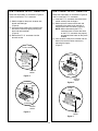
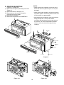
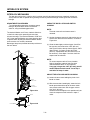
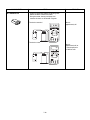
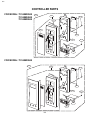
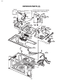
A. REMOVING POWER AND CONTROL
CIRCUIT BOARD (Figures 1, 2 and 3)
(1) Remove a screw securing the control panel
assembly to the oven cavity.
(2) Remove the control panel with pushing it upward.
(3) Remove the five connectors (CN1, CN2, CN4,
CN5, CN6) and wire leads (Relay8, Relay10) from
the circuit board.
(4) Remove 3 screws securing the circuit board.
Control Panel
Screw
Power
Transformer
(Relay 8)
(CN1)
(Relay 10)
(CN4)
(CN6)
(CN5)
(CN2)
FPC Connector(S1)
Control Bracket
Circuit Board
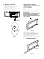
(5) Remove the FPC connector from the terminal
socket following “HOW TO REMOVE THE FPC
CONNECTOR” on the next page.
(6) Remove the circuit board from the control bracket
carefully.
Figure 1
Figure 2
Figure 3

7-5
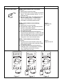
HOW TO REMOVE THE F.P.C. CONNECTOR
Follow the steps below as illustrated in Figures 4
and 5 to remove the F.P.C. connector.
(1) Hold the edges of the plastic fastener with
thumb and forefinger.
(Figure 4)
(2) Lift up the lever of the plastic fastener from
the terminal socket by lightly pressing the
lever end with forefinger.
(Figure 5)
(3) Remove the F.P.C. connector from the
terminal socket.
HOW TO INSERT THE F.P.C. CONNECTOR
Follow the steps below as illustrated in Figures 6
and 7 to insert the F.P.C. connector.
(1) Insert the F.P.C. connector into the terminal
socket securely with the fingers.
(2) Hold the plastic fastener with thumb and
forefinger of the other hand, and push it
slowly into the terminal socket. (Figure 6)
NOTE: When reconnecting the F.P.C.
connector make sure that the holes
on the F.P.C. connector are properly
engaged with the hooks on the plastic
fastener
(3) Lock the level of the plastic fastener into the
hook of the terminal socket securely by
releasing the fingers.
(Figure 7)
Figure 4
Figure 6
Figure 7
Figure 5
F.P.C.
Connector
Terminal
socket
Plastic
fastener
Holes
Hook
Plastic fastener
Terminal
socket
F.P.C.
Connector
Plastic
fastener
Terminal
socket
F.P.C.
Connector
Terminal
socket
Plastic fastener
Holes
Hook

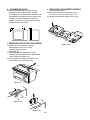
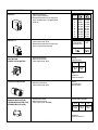
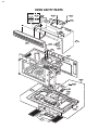
7-6
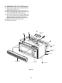
B. REMOVING THE OUT CASE(Figure 8)
(1) Remove the vent grille by removing two screws
securing it to the out case.
(2) Remove two screws securing it to the air duct.
(3) Remove the mounting plate by turning the screws
(1 or 2 screws)securing it to the out case.
(4) Remove two screws on the left central edge and
one screw on the right central edge of Base plate.
Remove the Mount, All from the out case by
removing one screw securing it to the out case.
(5) Remove six screws of the rear cavity.
(6) Remove the outcase.
Controller
(3 screws)
Door
Mounting
Plate
(1 or 2 screws)
Out Case
Mount,All
Vent Grille
Figure 8

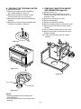
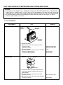
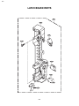
7-7
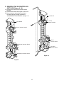
C. REMOVING THE DOOR INTERLOCK
SWITCHES (Figures 9, 10)
(1) Disconnect the wire leads from the interlock
switches.
(2) Remove two screws securing the Latch Board.
(3) Make necessary replacements and check
microwave energy leakage according to
“ADJUSTMENT PROCEDURES” on page 7-12.
Latch Board
Primary Interlock Switch
Monitor Interlock Switch
Secondary Interlock Switch
Latch Board
Primary
Interlock Switch
Monitor
Interlock Switch
Secondary
Interlock Switch
Figure 9
Figure 10

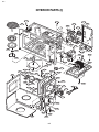
7-8
D. REMOVING MAGNETRON
(Figures 11 Through 13b)
(1) Remove the vent grille by loosening two screws.
(Figure 11)
(2) Remove the outcase. See page 7-6.
(3) Remove four tap tite screws securing the
magnetron to the wave guide.
(4) Disconnect the leadwire.
(5) Remove the magnetron VERY CAREFULLY.
NOTES:
• When removing the magnetron, make sure that its
dome does not hit any adjacent parts, or it may be
damaged.
• When replacing the magnetron, be sure to install the
magnetron gasket in the correct position and be sure
that the gasket is in good condition.
• After replacing the magnetron, check for microwave
energy leakage with a survey meter Check
microwave energy leakage must be below the limit
of 5 mW/cm
2
. (All service adjustments should be
made for minimum microwave energy leakage
readings.)
Figure 11
Figure 13-a Figure 13-b
Figure 12
Vent Grille
Controller
(3 screws)
Door
Mounting
Plate
(1 or 2 screws)
Out Case
Mount,All

7-9
E. REMOVING STIRRER FAN
(Figures 14 and 15)
(1) Remove two screws securing it to the oven
upper plate by using drive screw.
(2) Rotate slightly and pull out the stirrer fan cover.
(3) Remove the stirrer fan.
F. REMOVING DOOR (Figure 16)
(1) Remove the vent grille by two screws securing it to
the outcase loosening.
(2) Lift up and draw the door.
NOTES:
• After replacing the door, be sure to check that the
primary interlock switch, the secondary interlock
switch and the interlock monitor switch is in good
operating normally.
• After replacing the door, check for microwave energy
leakage with a survey meter. Microwave energy
leakage must be below the limit of 5mW/cmcm
2
. (With
a 275 ml water load)
G. DISASSEMBLING DOOR (Figure 17)
(1) Remove the dielectric choke by using knife
blade or small screw driver, etc.
(2) Remove two screws securing it to the door handle.
CAUTION: Be careful not to damage door seal
plate with the screwdriver.
Figure 15
Figure 14
Figure 18
Door Screen
Figure 19
Page is loading ...
Page is loading ...
Page is loading ...
Page is loading ...
Page is loading ...
Page is loading ...
Page is loading ...
Page is loading ...
Page is loading ...
Page is loading ...
Page is loading ...
Page is loading ...
Page is loading ...
Page is loading ...
Page is loading ...
Page is loading ...
Page is loading ...
Page is loading ...
Page is loading ...
Page is loading ...
Page is loading ...
Page is loading ...
Page is loading ...
Page is loading ...
Page is loading ...
Page is loading ...
Page is loading ...
-
 1
1
-
 2
2
-
 3
3
-
 4
4
-
 5
5
-
 6
6
-
 7
7
-
 8
8
-
 9
9
-
 10
10
-
 11
11
-
 12
12
-
 13
13
-
 14
14
-
 15
15
-
 16
16
-
 17
17
-
 18
18
-
 19
19
-
 20
20
-
 21
21
-
 22
22
-
 23
23
-
 24
24
-
 25
25
-
 26
26
-
 27
27
-
 28
28
-
 29
29
-
 30
30
-
 31
31
-
 32
32
-
 33
33
-
 34
34
-
 35
35
-
 36
36
-
 37
37
-
 38
38
-
 39
39
-
 40
40
-
 41
41
-
 42
42
-
 43
43
-
 44
44
-
 45
45
-
 46
46
-
 47
47


Kenmore 721.80822500 Owner's manual
- Category
- Microwaves
- Type
- Owner's manual
- This manual is also suitable for
Ask a question and I''ll find the answer in the document
Finding information in a document is now easier with AI
Related papers
-
Sears Microwave Oven Owner's manual
-
Kenmore 80824 Installation guide
-
-
Sears 721.67902 Owner's manual
-
-
Kenmore 88519 Installation guide
-
-
LG 721.63663 Owner's manual
-
-
Other documents
-
Goldstar MV-1525B User manual
-
-
-
Maytag MMV5165AAQ Owner's manual
-
Kenroy Home 32843BL Installation guide
-
-
LG DOTRC17SSC Owner's manual
-
LG LMH2016SW Installation guide
-
-