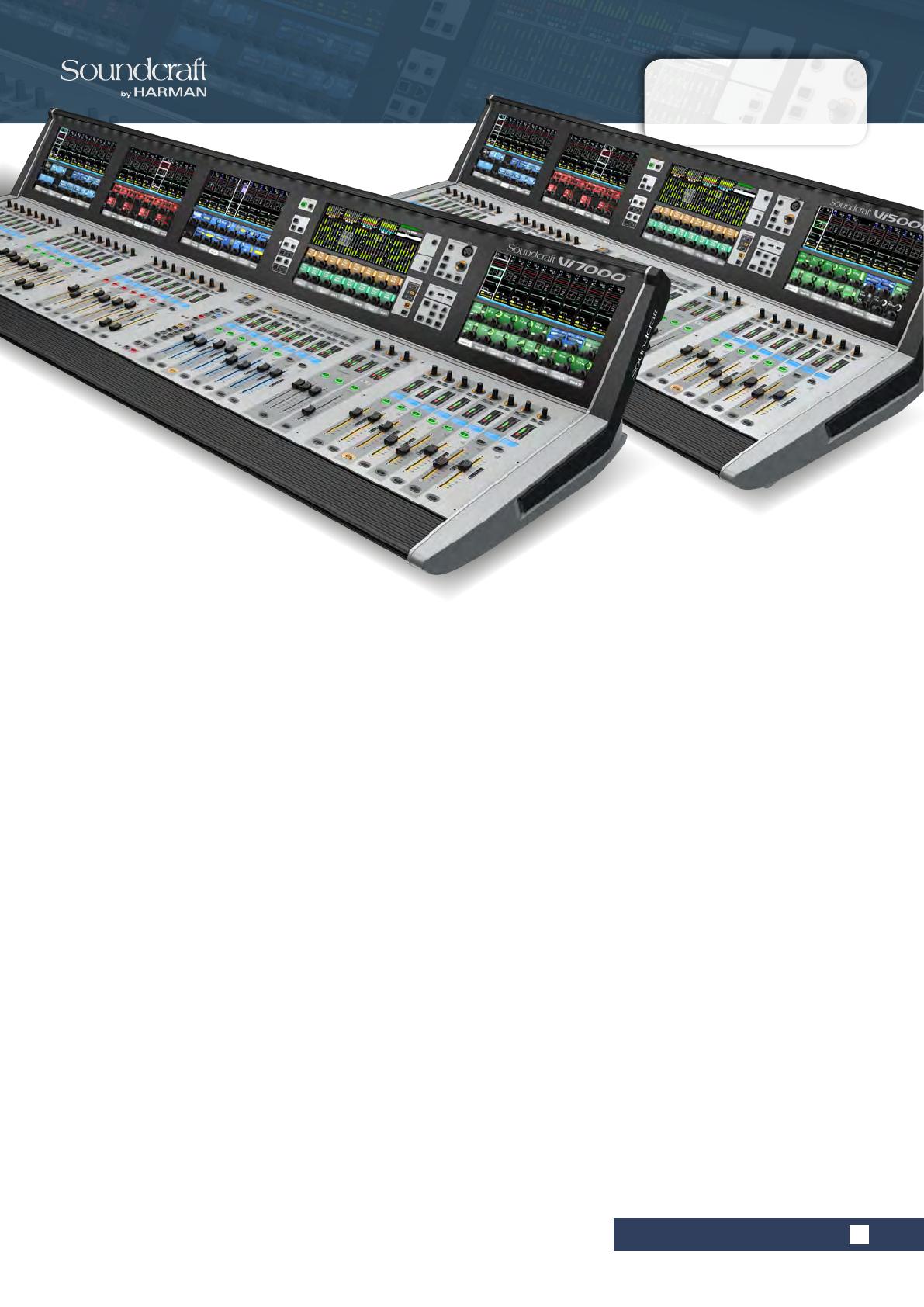
Vi5000/7000 User Manual
1.0: INTRODUCTION
1.0: INTRODUCTION
INTRODUCTION
Live sound mixing - the way it should be
Our patented Vistonics was designed from a simple start
point - create the most intuitive digital mix interface
available. Vistonics simplies the process and puts the
rotary encoders and switches right on the touch screen.
With an adaptive graphics and relevant controls
combined in one area, the operator is immediately
presented with a simple, clear mix system that
streamlines workow and enhances the creative process.
Each Vistonics interface controls eight input channels
and comprises a touch screen with 16 rotary encoders
and 16 switches. A simple touch in the desired part of the
on-screen channel strip is all it takes to access channel
functions including routing, input gain, digital gain trim,
delay, high and low pass lters, 4-band fully parametric
EQ, compressor, limiter, gate, de-esser and pan, with
immediate access to a sophisticated visual status display
and straightforward controls.
Fader layers - like you’ve never seen them before
In the heat of the moment, with the faders ying, fader
layers can cause all kinds of headaches. Soundcraft®
FaderGlow solves the problem associated with multiple
fader layers. At a single glance, illuminated faders in
colours that match those on the Vistonics™; display show
immediately what function a fader is controlling.
When controlling inputs, no illumination is applied to the
motorised faders. But when the Aux, Group or Matrix bus
master is soloed with the Follow Solo function switched
on, the fader becomes a ‘contributor’ for the soloed bus,
lighting up in orange, green or blue accordingly.
A console focused on the operator
User-congurable fader layers allow an engineer to
map out channels on any of 5 user layers so that a
combination of different inputs can be placed on one
layer.
Output fader layers can also be customised; for example,
stereo aux masters can be placed alongside VCAs or
matrix masters for faster access to priority outputs.
Every aspect of the control surface, mechanical and
operational, has been engineered around the operator to
provide an unimpeded workow and a more creative mix.
The angle of the touch screens ensures that the engineer
can always view display data clearly during the show.
The brightness and contrast of the displays, and the
illumination of the control surface itself, are designed to
minimise strain on the eye. By optimising the density of
faders and controls on the operating surface, the
engineer is able to reach all critical areas of the console
comfortably from a central point, without straining or
leaning over.
Welcome To Soundcraft Vi


