3M Snowshoes 747 User manual
- Category
- Measuring, testing & control
- Type
- User manual
This manual is also suitable for

User’s Guide
3M
™
Shoes and Wrist Strap Tester 747

1
Table of Contents
Section Page
Introduction ......................................................................................................................................2
Inspection .........................................................................................................................................2
Package Contents ..............................................................................................................................2
Safety Information ............................................................................................................................3
Intended Use .....................................................................................................................................3
Chapter 1.0 Overview ..................................................................................................................5
1.1 Product outline .........................................................................................................5
1.2 Part Names and Functions .......................................................................................6
1.2.1 Front Panel ...............................................................................................................6
1.2.2 Side Panels ...............................................................................................................7
1.2.3 Back Side .................................................................................................................7
Chapter 2.0 Preparation Before Testing .......................................................................................8
2.1 Connecting the ESD Shoe Testing ...........................................................................8
2.2 Threshold Resistance Settings .................................................................................9
2.3 Power Preparation ..................................................................................................10
2.3.1 Installing and Replacing the Batteries ..................................................................10
2.3.2 AC Adapter Connection .........................................................................................11
2.4 Turning Power On and Off .....................................................................................11
2.5 Wall Mounting .......................................................................................................12
Chapter 3.0 Testing ....................................................................................................................12
3.1 ESD Shoe Testing ...................................................................................................13
3.2 ESD Wrist Strap Testing ........................................................................................14
Chapter 4.0 External Output Function ......................................................................................14
4.1 Open Collector Output ...........................................................................................14
4.2 RS-232C Communications ....................................................................................18
4.3 Card Read Technical Specifications .......................................................................19
4.4 PC System Requirements .......................................................................................19
Chapter 5.0 Specification ..........................................................................................................20
5.1 Measurement Section .............................................................................................20
5.2 General Specifications ...........................................................................................21
Chapter 6.0 Maintenance & Service..........................................................................................21
6.1 Battery Replacement Indicator ..............................................................................21
6.2 Error Messages ......................................................................................................22
6.3 Before Returning the 3M
™
Shoes and Wrist Strap Tester 747 for Service .............22
6.4 Cleaning .................................................................................................................23
Chapter 7.0 Operational Verification Test of Shoes and Wrist Strap Tester 747 .......................23
Regulatory Information ..................................................................................................................27
Warranty .........................................................................................................................................29

2
Introduction
Thank you for purchasing this 3M
™
Shoes and Wrist Strap Tester 747. To get the
maximum performance from the unit, please read this user’s guide first, and refer
to it as needed.
Inspection
The AC adapter provided with the Shoes and Wrist Strap Tester 747 varies
according to region. In North America, the Shoes and Wrist Strap Tester 747 is
provided with the SA10-0910N AC adapter, while in Europe it is provided with
the SA 10-0910G AC adapter. Before using the Shoes and Wrist Strap Tester
747, make sure that you have the correct AC adapter for your region.
When the unit is delivered, check and make sure that it has not been damaged,
or fails to operate according to the specifications, contact your dealer or 3M
representative.
Package Contents
AC Adapter 1
ESD Shoe Testing Cord 1
Wall-Mounting Board 1
3M
™
Data Logging Software 747DLS 1
ESD Shoe Testing Plate 1
Mounting Screw for ESD Shoe Testing Plate (with washer) 1
Alkaline Battery 6
Null Modem Cable 1.8 m 1
Quick Guide Test Card 1

3
SAFETY INFORMATION
Read, understand and follow all safety information before operating this
equipment. Retain this User’s Guide for future reference.
Intended Use:
The 3M
™
Shoes and Wrist Strap Tester 747 is a single-unit instrument designed
especially to measure electrical resistance for evaluating the effectiveness
of ESD (electrostatic discharge) shoes and wrist straps used to protect static
sensitive devices during handling.
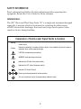
Explanation of Safety Label Signal Words & Symbols
Warning
Indicates a potentially hazardous situation, which, if not avoided, may result in death or
serious injury.
Caution
Indicates a potentially hazardous situation, which, if not avoided, may result in minor or
moderate injury and/or property damage.
CAUTION: read operating instructions
WARNING: read operating instructions
Indicates the ON side of the power switch.
Indicates the OFF side of the power switch.
Indicates DC (Direct Current).
Power input connector polarity (center positive)
See user instruction manual for explanation of indicator lamps

4
Do not use power supply to power unit in Europe. Unit is intended to be powered by non-rechargeable
battery and input connector is not to be used.
To reduce the risks associated with an explosion hazard, which, if not avoided, could result in death or
serious injury:
• Do not use in an explosive environment. 3M
™
Shoe and Wrist Strap Tester 747 is not designed to be
intrinsically safe.
To reduce the risks associated with a medical device malfunction, which, if not avoided, could result in
death or serious injury:
• Persons with heart pacemaker devices should never use this Shoes and Wrist Strap Tester 747.
WARNING
To reduce the risks associated with hazardous voltage, which, if not avoided,, may result in minor or
moderate injury and/or property damage:
• AC adapter must have all local required regulatory certifications.
• Do not use AC adapter and/or power cord if damaged.
• When replacing batteries, turn the power switch off and disconnect all the cables before beginning.
• Do not use in an outdoor and/or wet environment.
• Not intended to be serviced by the user. No user serviceable parts.
• Always replace battery cover before using the Shoes and Wrist Strap Tester 747.
To reduce the risks associated with electrostatic discharge (ESD), which, if not avoided, may result in
property damage to electronic components or assemblies being handled:
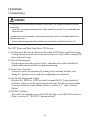
• Perform operational verification test to ensure proper operation of the Shoes and Wrist Strap Tester
747 as required.
To reduce the risk associated with environmental contamination, which, if not avoided, may result in-
contamination of land, water or air:
• Dispose of Shoes and Wrist Strap Tester 747 and/or batteries in accordance with governmental
regulations at the end of product-life.
CAUTION

5
1.0 Overview
1.1 Product Outline
To reduce the risks associated with an explosion hazard, which, if not avoided, could result in death or
serious injury:
• Do not use in an explosive environment. 3M
™
Shoes and Wrist Strap Tester 747 is not designed to be
intrinsically safe.
To reduce the risks associated with a medical device malfunction, which, if not avoided, could result in
death or serious injury:
• Persons with heart pacemaker devices should never use this Shoes and Wrist Strap Tester 747.
WARNING
The 3M
™
Shoes and Wrist Strap Tester 747 features:
(1) Evaluation of Electrostate Protection Provided by ESD Shoes and Wrist Straps
A single device measures the electrical resistance of a body while wearing ESD
shoes and wrist straps.
(2) Quick Measurements
Displays measures value and test results, and makes the results available for
output within one second after starting measurement.
(3) Power Saver Function
Conservers power by automatically turning off (or entering stand-by state
during AC operation) ten second after completing a measurement.
(4) Test Result Display and Output
Displays OK, HIGH, or LOW test results on panel LEDs. Testing threshold
resistance values are set by simple switch selections. Results are also available
at an open-collector output terminal. Refer to Section 4.1, “Open Collector
Output.”
(5) RS-232C Interface
Test results are available to an external PC through a serial (RS-232C) interface.
Refer to section 4.2, “RS-232C Communications.”

6
1.2 Part Names of the 3M
™
Shoes and Wrist Strap Tester 747
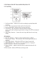
1.2.1 Front Panel
1. Test Result LEDs
–
Indicates test results according to specified threshold
resistance.
2. LCD – Shows
measurement values and test location status.
3. Test Location LEDs
–
Indicate the test location and status.
4. Touch Panel
–
The touch panel is the measurement terminal.
(power switch and touching the panel initiate testing of the ESD measurement
terminal)
5. Wrist Strap Connector
–
Connect the wrist strap cable here for wrist strap
testing
LCD Indicators
6. RS-232C Indicator
–
Indicates serial communications is enabled.
7. Measurement Display
–
The measured value, decimal point and units are
displayed
8. Wrist Strap Symbol
–
Indicated an ESD wrist strap is being tested.
9. MEASURE Indicator
–
Indicates a test (measurement) is in progress.
10. HOLD Indicator
–
Indicates a test is finished.
11. Battery Symbol
–
Appears when the battery is depleted and needs to be
replaced.
12. Shoe Symbol
–
Indicates ESD shoes are being tested.

7
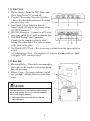
1.2.2 Side Panels
1.
Power Switch
–
Turns the 3M
™
Shoes and
Wrist Strap Tester 747 on and off.
2.
Threshold Resistance Selection Switches
– Select the threshold resistances for shoes
and wrist strap tests.
3.
Test Result Output Selection Switch –
Selects which test results are present at the
OUTPUT terminal.
4. RS-232C Connector
–
Connect to a PC serial
port using an RS-232C cable to transfer data.
5. ESD Shoe Testing
Cable Connector –
Connect to the supplied cable for shoe
testing. The other end of this cable connects
to the shoe testing plate.
6. Test Result OUPUT Jack
– Test results are available from this open-collector
output.
7. AC Adapter Input Jack – The supplied AC Adapter is connected here. Input
voltage is 9VDC, center positive.
1.2.3 Back Side
1. Mounting Holes
–
These holes accommodate
the hooks on the supplied wall-mount board
for wall mounting.
2. Battery Cover
– To operate batteries, install
six “penlight” alkaline batteries under this
cover.
To reduce the risks associated with hazardous voltage,
which, if not avoided, may result in minor or moderate
injury and/or property damage:
• Not intended to be serviced by the user. No user
serviceable parts.
CAUTION

8
2.0 Preparation Before Testing
2.1 Connecting the ESD Shoe Testing Plate
To reduce the risks associated with an explosion hazard, which, if not avoided, could result in death or
serious injury:
• Do not use in an explosive environment. 3M
™
Shoes and Wrist Strap Tester 747 is not designed to be
intrinsically safe.
WARNING
To reduce the risks associated with hazardous voltage, which, if not avoided, may result in minor or
moderate injury and/or property damage:
• Do not use in an outdoor and/or wet environment.
CAUTION
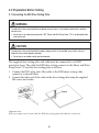
The supplied shoe testing plate and cable must be connected to test ESD
protective shoes. The cable for ESD shoe testing connects to the Shoes and Wrist
Strap Tester 747 and the shoe testing plate as follows:
1. Connect the BNC-plug end of the cable to the ESD shoes testing cable
connector as shown below.
2. Connect the other end of the cable in the shoe testing plate using the supplied
M4 screw and washer.
Important Note:
ESD wrist straps can be tested while the ESD shoe testing plate and cable are connected.

9
2.2 Threshold Resistance Settings for the 3M
™
Shoes and Wrist Strap Tester 747
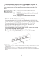
The test results indicated by the front panel LEDs are determined by comparison
of the measured value with the threshold resistance settings (upper and lower
limits).
LOW: the measured resistance is below the lower
threshold
OK: the measured resistance is between the lower and
upper thresholds
HIGH: the measured resistance is above the upper
threshold
1. ESD Shoe Test Threshold Resistance Settings
The upper threshold (SHOES HIGH) and lower threshold (SHOES LOW)
can be selected for shoe testing. Use tweezers to move the threshold switches
The upper threshold (SHOES HIGH) selections are 10, 35 or 100 Ω.
The lower threshold (SHOES LOW) selections are 100 kΩ or 1 Ω.
2. ESD Wrist Strap Test Threshold Resistance Settings
The upper threshold (WRIST HIGH) can be selected for wrist strap testing.
Use tweezers to move the threshold switch.
The lower threshold is fixed at 1.65 Ω for wrist strap testing.
The upper threshold (WRIST HIGH) selections are 5, 10 or 35 MΩ.
Important Notes:
• Factory default settings are 100 MΩ for SHOES HIGH, and 10 MΩ for WRIST HIGH, and 1 MΩ
for SHOES LOW.
• The SIGNAL OUT selection is set to SHOES. When operated as a stand-alone tester (that is,
when not using the external output), this SIGNAL OUT selection should be set to either WRIST or
SHOES.

10
2.3 Power Preparation
2.3.1 Installing and Replacing the Batteries
Important Notes:
• To avoid electric shock when replacing the batteries, turn the power switch off and disconnect the
all cables before beginning. Also, after replacing the batteries, always replace the cover before
using the unit.
• When replacing the batteries, do not install old batteries with new ones, and do not mix different
types of batteries. Check the battery polarity carefully when inserting the batteries.
• Do not short-circuit used batteries, disassemble them, or throw them in a fire. Doing so may cause
the batteries to explode.
• Keep used batteries out of the reach of children. Dispose of used batteries according to their type
in the prescribed manner and in the proper location.
• Remove the batteries before storage to prevent possible corrosion caused by battery leakage if the
Shoes and Wrist Strap Tester 747 will not be used for a long period of time.
• When using the AC adapter, remove the batteries from the Shoes and Wrist Strap Tester 747 to
prevent corrosion due to possible electrolyte leakage.
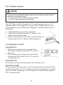
This 3M
™
Shoes and Wrist Strap Tester 747
can be operated from six “AA” alkaline
batteries or the supplied AC adapter. The AC
adapter has priority, so when the batteries are
installed and the adapter is connected, battery
power is not drained.
1. Confirm that the power switch is turned off.
2. Disconnect all cables from the Shoes and
Wrist Strap Tester 747.
3. Remove the battery cover from the rear
panel, and insert six fresh type “AA”
batteries, with careful attention to the
indicated polarity.
4. Replace the battery cover securely.
To reduce the risks associated with hazardous voltage, which, if not avoided, may result in minor or
moderate injury and/or property damage:
• When placing batteries, turn the power switch off an disconnect all the cables before beginning.
• Always replace battery cover before using the 3M
™
Shoes and Wrist Strap Tester 747.
CAUTION

11
2.3.2 AC Adapter Connection
This 3M
™
Shoes and Wrist Strap Tester 747 can be operated from six “AA”
alkaline batteries or the supplied AC adapter. The AC adapter has priority, so
when the batteries are installed and the adapted is connected, battery power is
not drained.
1. Confirm that the power switch is turned off.
2. Connect the output plug from the AC Adapter to the
mating jack on the side panel.
3. Check to ensure that your AC mains voltage matches the
voltage rating of the AC Adapter, and then plug it in.
2.4 Turning Power On and Off
Turning Power On
1. Set the power switch on the side panel of the
3M
™
Shoes and Wrist Strap Tester 747 to the on
position (|).
2. Press a finger on the touch panel on the front of
the Shoes and Wrist Strap Tester 747 to switch it
on and begin a test.
Turning Power Off
Set the power switch on the side panel to the off position (O).
Power Saver Function
The power saver function conserves power by automatically turning the Shoes
and Wrist Strap Tester 747 off (or entering stand-by state during AC operation)
ten seconds after completing a test. This function is disabled when using RS-
232C communications.
To reduce the risks associated with hazardous voltage, which, if not avoided, may result in minor or
moderate injury and/or property damage:
• AC adapter must have all local required regulatory certifications.
• Do not use AC adapter and/or power cord if damaged.
CAUTION

12
Important Note:
When operating on batteries, the power saver function minimizes battery drain, although a very
small amount of current is still required by the tester. Turn the power switch off to completely
disconnect the batteries.
2.5 Wall Mounting
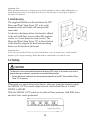
The supplied Wall-Mount Board allows the 3M
™
Shoes and Wrist Strap Tester 747 to be easily
mounted on the wall while still being readily
removable.
As shown in the figure below, the board is affixed
to the wall with three screws (either M4 machine
screws or 4.1 mm diameter wood screws). The
Shoes and Wrist Strap Tester 747 is then attached
to the board by align in the back-side mounting
holes over the hooks on the board.
Important Note:
Screws are not included. Please use either M4 machine screws or wood screws with a nominal
diameter of 4.1 mm for mounting. Either flat head or round head screws may be used.
3.0 Testing
When used as a stand-alone tester (that is, when not using the external output),
the SIGNAL OUT test result output selector switch should be set to either
WRIST or SHOES.
With the SIGNAL OUT switch set to either of these positions, both ESD shoes
and wrist tests can be performed.
To reduce the risks associated with electrostatic discharge (ESD), which, if not avoided, may result in
property damage to electronic components or assemblies being handled.
• Perform operational verification test to ensure proper operation of the 3M
™
Shoes and Wrist Strap
Tester 747 as required.
CAUTION

13
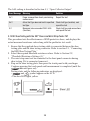
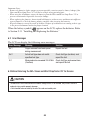
The ALL setting is described in Section 4.1, “Open Collector Output.”
Error Message Meaning Solution
Err.1 Finger removed from touch panel during
measurement
Repeat the test
Err.2 Actual test type does not match specified
test type
Check test type (location), and
repeat the test
O.F. Measured value exceeded 200.0 MΩ
(Overflow)
Check test type and connections,
and repeat the test
3.1 ESD Shoe Testing with the 3M
™
Shoes and Wrist Strap Tester 747
This procedure tests the effectiveness of ESD protective shoes, and displays the
actual measured resistance value along with the qualitative test result.
1. Ensure that the supplied shoes testing cable is connected between the shoe
testing plate and the shoe testing connector. Refer to section 2.1, “Connecting
the ESD Shoe Testing Plate.”
2. Select the required threshold resistance values. Refer to Section 2.2,
“Threshold Resistance Settings (1).”
3. The wrist strap must not be connected to the front panel connector during
shoe testing. If it is connected, remove it.
4. Step on the shoe testing plate, then press the touch panel with your finger.
Continue pressing the touch panel until measurement is completed (until the
indicator goes out).
Testing starts and the following indicators are displayed:
• and
symbol appear on the LCD.
• The shoe LED lights yellow.

14
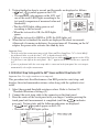
5. Testing finished in about a second, and the results are displayed as follows:
• and
symbol appear on the LCD.
• The measured value appears on the LCD, and
one of the result LEDs lights according to the
test result (comparison of measured value and
thresholds).
• The shoe LED lights either green or red
according to the test result:
• When the test result is OK, the LED lights
green.
• When the test result is HIGH or LOW, the LED lights red.
6. When the test is finished, the results are displayed for about ten seconds.
Afterwards, if running on batteries, the power turns off. If running on the AC
adapter, the power saver activates the stand-by state.
Important Notes:
• The high end of the measurement range of the Shoes and Wrist Strap Tester 747 is 200.0 MΩ. If
the measured value exceeds this limit, “O.F.” is displayed on the LCD.
• If the finger is removed from the touch panel during a test (while appears on the LCD),
or if pressure is too light on the touch panel, “Err.1” appears on the LCD. In this case, repeat the
test.
• If a test is performed while the wrist strap cable is connected to the front panel, the wrist strap is
automatically selected for measurement.
3.2 ESD Wrist Strap Testing with the 3M
™
Shoes and Wrist Strap Tester 747
Important Note: Use single-conductor wrist straps only.
This procedure tests the effectiveness of an ESD protective wrist strap, and
displays the actual measured resistance value along with the qualitative test
result.
1. Select the required threshold resistance values. Refer to Section 2.2,
“Threshold Resistance Settings (2).”
2. Connect the wrist strap cable to the connector on the front panel.
3. Press the center of the touch panel with your finger. Continue pressing the
touch panel until measurement is completed (until the indicator
goes out). Testing starts and the following indicators are displayed:
• and
symbol appear on the LCD.
• The wrist strap LED lights yellow.

15
4. Testing finished in about a second, and the results are displayed as follows:
• and
symbol appears on the LCD.
• The measured value appears on the
LCD, and one of the result LEDs lights
according to the test result (comparison of
measured value and thresholds).
• The wrist strap LED lights either green or
red according to the test result:
• When the test result is OK, the LED lights
green.
• When the test result is HIGH or LOW, the
LED lights red.
5. When the test is finished, the results are displayed for about ten seconds.
Afterwards, if running on batteries, the power turns off. If running on the AC
adapter, the power saver activates the stand-by state.
Important Notes:
• The high end of the measurement range of the 3M
™
Shoes and Wrist Strap Tester 747 is 200.0 MΩ.
If the measured value exceeds this limit, “O.F.” is displayed on the LCD.
• If the finger is removed from the touch panel during a test (while appears on the LCD),
or if pressure is too light on the touch panel, “Err.1” appears on the LCD. In this case, repeat the
test.
• Wrist strap testing can be done even when the shoe testing cable and plate are connected.
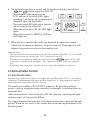
4.0 External Output Function
4.1 Open Collector Output
Important Note: Always turn the power switch off the Shoes and Wrist Strap Tester 747 when making
connections. To avoid damage to the Shoes and Wrist Strap Tester 747, do not apply more than the
rated voltage and current of the OUTPUT connector.
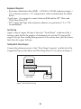
Test results are available at the OUTPUT connector. By providing external
power, a relay or sequencer can be controlled, for example, to open and close an
automatic door.
After a measurement, if the test result is OK, the transistor controlling the open-
collector output will turn on for 400 ms.
The output transistor functions as a switch between the output signal and internal
ground. When the test result is OK, current flows from the output terminal to the
internal ground.

16
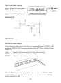
Test Result Output Terminal
Mating Plug (stereo mini-phone)
Mating Plug Size:
14 mm by 13.5 mm diameter
Open Collector Output Ratings
Internal Circuit
Important Note:
Mating plus not included. Please ensure that the plus used is of the type indicated above.
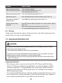
Test Result Output Settings
Using tweezers, select the test result type to be provided at the OUTPUT jack
using the SIGNAL OUT switch on the side of the 3M
™
Shoes and Wrist Strap
Tester 747.
ALL: Results of both shoe and wrist strap tests are output.
WRIST: Only wrist strap test results are output.
SHOES: Only shoe test results are output.
The OUTPUT terminal transistor will not turn on unless the SIGNAL OUT
switch setting corresponds with the type of actual test performed, even if the
result of that test is OK.

17
Open-Collector Output
• When the SIGNAL OUT switch is set to ALL:
The output transistor switches on when the results of the shoe and wrist strap
test are OK. When making alternating shoe/wrist strap tests, the type of test
to be conducted next is indicated by the blinking symbol on the LCD and the
blinking LED.
• When the SIGNAL OUT switch is set to WRIST:
The output transistor is on when the result of a wrist strap test is OK.
• When the SIGNAL OUT switch is set to SHOES:
The output transistor is on when the result of a shoe test is OK.
Shoe and Wrist Strap (ALL) Setting
• If you attempt to test while the wrist strap LED is blinking and without having
the wrist strap connected to the Shoes and Wrist Strap Tester 747, “Err.2”
appears on the LCD. In this case, connect the wrist strap cable to the front
panel connector and test again.
• Conducting a wrist strap test followed immediately by a shoe test allows the
shoe test to be performed while the wrist strap remains connected to the front
panel when testing one shoe only.
Important Note:
Using the 3M
™
Software 747DLS with the 3M
™
Shoes and Wrist Strap Tester 747 requires the
following action: When testing a wrist strap and two shoes, the wrist strap ground cord must be
disconnected from the Shoes and Wrist Strap Tester 747 after testing the wrist strap to perform the
shoes test.
• If more than ten seconds elapse between a shoe test and a wrist strap test, the
automatic power-off function clears the last test results. In this case, repeat the
last test.

18
4.2 RS-232C Communications
Important Notes:
• Always turn the power switch off when making connections. To avoid damage to the Shoes and
Wrist Strap Tester 747, do not apply more than the rated voltage and current to the OUTPUT
connector.
• To avoid damage to the unit, do not short or input voltage to the RS-232C terminal.
• When connecting the RS-232C cable, always secure with the thumb screws.
• To use the communication function, the unit must be operating with the AC adapter connected.
• In order to avoid electric shock, turn off the power to all devices before plugging in or unplugging
any of the interface connectors.
Test results can be transferred to a PC by RS-232C communications.
Communications can begin when the Shoes and Wrist Strap Tester 747 is
operating or in stand-by state. To activate the stand-by state, place a finger on the
touch panel while turning the power switch on, then wait ten seconds.
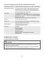
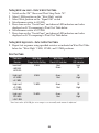
Specifications
The RS232-C settings of the Shoes and Wrist Strap Tester 747 are as follows.
These setting cannot be changed, so the serial port settings on the PC must be set
to match.
Transmission speed
4800 bps
Data length 8 bits
Stop bits
1 bit
Parity bit None
Handshaking None (no X-flow or hardware)
Delimeters Receive: CR+LF, CP. Transmit: CR+LF
Connector 9-pin D-sub male, accepts M2.6 screws
To reduce the risks associated with hazardous voltage, which, if not avoided, may result in minor or
moderate injury and/or property damage:
• Always replace battery cover before using the 3M
™
Shoes and Wrist Strap Tester.
CAUTION

19
Pin Signal I/O Description
2 RxD IN Receiving Data
3
TxD OUT Sending Data
5 GND GND Signal Ground
Other pins are not used.
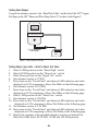
PC Connection
The RS-232C signal wires used are as follows (no other lines are used).
Cable Connections
The 3M
™
Shoes and Wrist Strap Tester 747 connects
to the PC through a crossover cable. The transmit and
receive lines are crossed, and the ground lines connect
together. The other lines are ignored, but hardware flow
control must be disabled at the PC side.
Cable wiring at Shoes and Wrist Strap Tester 747 end:
cross-connected
4.3 Card Reader Technical Specifications
Serial Interface Specification:
Bit Rate:
110, 300, 1200, 2400, 4800, 9600, 19200, 38400, 57600, 115200 (selectable)
Word Length:
Data Format – 4, 5, 6, 7, 8 (selectable)
Parity Bit – Even, Off, None, Mark, Space (selectable)
Stop Bit – 1, 1.5, 2 (selectable)
Handshaking (Flow Control):
None, Xon/Xoff, RTS/CTS, RTS/XonXoff (selectable)
Proximity Card Reader:
Message Indicator
Start of Text – Single ASCII Character
End of Text and CR – Single ASCII character
4.4 PC System Requirements
Check with 3M as PC System requirements and Software compatibility may
differ as new Operating Systems change.
Page is loading ...
Page is loading ...
Page is loading ...
Page is loading ...
Page is loading ...
Page is loading ...
Page is loading ...
Page is loading ...
Page is loading ...
Page is loading ...
-
 1
1
-
 2
2
-
 3
3
-
 4
4
-
 5
5
-
 6
6
-
 7
7
-
 8
8
-
 9
9
-
 10
10
-
 11
11
-
 12
12
-
 13
13
-
 14
14
-
 15
15
-
 16
16
-
 17
17
-
 18
18
-
 19
19
-
 20
20
-
 21
21
-
 22
22
-
 23
23
-
 24
24
-
 25
25
-
 26
26
-
 27
27
-
 28
28
-
 29
29
-
 30
30


3M Snowshoes 747 User manual
- Category
- Measuring, testing & control
- Type
- User manual
- This manual is also suitable for
Ask a question and I''ll find the answer in the document
Finding information in a document is now easier with AI
Related papers
Other documents
-
AFC IR600-003 Datasheet
-
Lindy Anti-Static Wrist Strap Operating instructions
-
 Warmbier PGT 120 User manual
-
Dell Precision 7730 Quick start guide
-
Dell Precision 5820 Tower Quick start guide
-
Dell Precision 7530 Quick start guide
-
Dell Latitude 5591 Quick start guide
-
Dell Latitude 7390 Owner's manual
-
Dellcos Chromebook 11-3120 Owner's manual
-
Dell Precision 7920 Tower Owner's manual
