Page is loading ...

cover 5/94 – ST-151 267-B PRINTED IN USA
1995 MILLER Electric Mfg. Co.
Read and follow these instructions and all
safety blocks carefully.
Have only trained and qualified persons
install, operate, or service this unit.
Call your distributor if you do not understand
the directions.
Give this manual to the operator.
For help, call your distributor
or: MILLER Electric Mfg. Co., P.O. Box 1079,
Appleton, WI 54912 414-734-9821
OWNER’S
MANUAL
May 1995 Form: OM-813A
Effective With Serial No. KC277447
Mounting Rack For Up To Eight XMT 300 Welding Power Sources With
AUTO-LINK
Uses Three-Phase Input Power
Requires Single Input Power Connection
Protection For Welding Power Sources, Control Circuitry, And Auxiliary
Power Transformer
Provides Isolated Terminal For Common Work Connections
Includes Two 120 VAC Duplex Receptacles
XMT 8-Rack

Miller Electric manufactures a full line
of welders and welding related equipment.
For information on other quality Miller
products, contact your local Miller distributor
to receive the latest full line catalog or
individual catalog sheets. To locate your nearest
distributor or service agency call 1-800-4-A-Miller,
or visit us at www.MillerWelds.com on the web.
Thank you and congratulations on choosing Miller. Now
you can get the job done and get it done right. We know
you don’t have time to do it any other way.
That’s why when Niels Miller first started building arc
welders in 1929, he made sure his products offered
long-lasting value and superior quality. Like you, his
customers couldn’t afford anything less. Miller products
had to be more than the best they could be. They had to
be the best you could buy.
Today, the people that build and sell Miller products continue the
tradition. They’re just as committed to providing equipment and service
that meets the high standards of quality and value established in 1929.
This Owner’s Manual is designed to help you get the most out of your
Miller products. Please take time to read the Safety precautions. They will
help you protect yourself against potential hazards on the worksite. We’ve
made installation and operation quick and easy.
With Miller you can count on years of reliable
service with proper maintenance. And if for
some reason the unit needs repair, there’s a
Troubleshooting section that will help you
figure out what the problem is. The parts list
will then help you to decide which exact part
you may need to fix the problem. Warranty and
service information for your particular model
are also provided.
Miller is the first welding
equipment manufacturer in
the U.S.A. to be registered to
the ISO 9001 Quality System
Standard.
Working as hard as you do
– every power source from
Miller is backed by the most
hassle-free warranty in the
business.
From Miller to You
Miller offers a Technical
Manual which provides
more detailed service and
parts information for your
unit. To obtain a Technical
Manual, contact your local
distributor. Your distributor
can also supply you with
Welding Process Manuals
such as SMAW, GTAW,
GMAW, and GMAW-P.

sr1.1.1 2/94
ARC WELDING SAFETY PRECAUTIONS
WARNING
PROTECT YOURSELF AND OTHERS FROM POSSIBLE SERIOUS INJURY OR DEATH. KEEP CHILDREN
AWAY. PACEMAKER WEARERS KEEP AWAY UNTIL CONSULTING YOUR DOCTOR.
In welding, as in most jobs, exposure to certain hazards occurs. Welding is safe when precautions are taken. The
safety information given below is only a summary of the more complete safety information that will be found in the
Safety Standards listed on the next page. Read and follow all Safety Standards.
HAVE ALL INSTALLATION, OPERATION, MAINTENANCE, AND REPAIR WORK PERFORMED ONLY BY
QUALIFIED PEOPLE.
ARC WELDING can be hazardous.
ELECTRIC SHOCK can kill.
Touching live electrical parts can cause fatal shocks
or severe burns. The electrode and work circuit is
electrically live whenever the output is on. The input
power circuit and machine internal circuits are also
live when power is on. In semiautomatic or automatic
wire welding, the wire, wire reel, drive roll housing, and
all metal parts touching the welding wire are
electrically live. Incorrectly installed or improperly
grounded equipment is a hazard.
1. Do not touch live electrical parts.
2. Wear dry, hole-free insulating gloves and body protection.
3. Insulate yourself from work and ground using dry insulating mats
or covers big enough to prevent any physical contact with the
work or ground.
4. Disconnect input power or stop engine before installing or
servicing this equipment. Lockout/tagout input power according
to OSHA 29 CFR 1910.147 (see Safety Standards).
5. Properly install and ground this equipment according to its
Owner’s Manual and national, state, and local codes.
6. Always verify the supply ground – check and be sure that input
power cord ground wire is properly connected to ground terminal
in disconnect box or that cord plug is connected to a properly
grounded receptacle outlet.
7. When making input connections, attach proper grounding
conductor first – double-check connections.
8. Frequently inspect input power cord for damage or bare wiring –
replace cord immediately if damaged – bare wiring can kill.
9. Turn off all equipment when not in use.
10. Do not use worn, damaged, undersized, or poorly spliced cables.
11. Do not drape cables over your body.
12. If earth grounding of the workpiece is required, ground it directly
with a separate cable – do not use work clamp or work cable.
13. Do not touch electrode if you are in contact with the work, ground,
or another electrode from a different machine.
14. Use only well-maintained equipment. Repair or replace
damaged parts at once. Maintain unit according to manual.
15. Wear a safety harness if working above floor level.
16. Keep all panels and covers securely in place.
17. Clamp work cable with good metal-to-metal contact to workpiece
or worktable as near the weld as practical.
ARC RAYS can burn eyes and skin;
NOISE can damage hearing; FLYING
SLAG OR SPARKS can injure eyes.
Arc rays from the welding process produce intense
visible and invisible (ultraviolet and infrared) rays that
can burn eyes and skin. Noise from some processes
can damage hearing. Chipping, grinding, and welds
cooling throw off pieces of metal or slag.
NOISE
1. Use approved ear plugs or ear muffs if noise level is high.
ARC RAYS
2. Wear a welding helmet fitted with a proper shade of filter to
protect your face and eyes when welding or watching (see ANSI
Z49.1 and Z87.1 listed in Safety Standards).
3. Wear approved safety glasses with side shields.
4. Use protective screens or barriers to protect others from flash
and glare; warn others not to watch the arc.
5. Wear protective clothing made from durable, flame-resistant
material (wool and leather) and foot protection.
FUMES AND GASES can be hazardous
to your health.
Welding produces fumes and gases. Breathing these
fumes and gases can be hazardous to your health.
1. Keep your head out of the fumes. Do not breathe the fumes.
2. If inside, ventilate the area and/or use exhaust at the arc to
remove welding fumes and gases.
3. If ventilation is poor, use an approved air-supplied respirator.
4. Read the Material Safety Data Sheets (MSDSs) and the
manufacturer’s instruction for metals, consumables, coatings,
cleaners, and degreasers.
5. Work in a confined space only if it is well ventilated, or while
wearing an air-supplied respirator. Always have a trained
watchperson nearby. Welding fumes and gases can displace air
and lower the oxygen level causing injury or death. Be sure the
breathing air is safe.
6. Do not weld in locations near degreasing, cleaning, or spraying
operations. The heat and rays of the arc can react with vapors to
form highly toxic and irritating gases.
7. Do not weld on coated metals, such as galvanized, lead, or
cadmium plated steel, unless the coating is removed from the
weld area, the area is well ventilated, and if necessary, while
wearing an air-supplied respirator. The coatings and any metals
containing these elements can give off toxic fumes if welded.
CYLINDERS can explode if damaged.
Shielding gas cylinders contain gas under high
pressure. If damaged, a cylinder can explode. Since
gas cylinders are normally part of the welding
process, be sure to treat them carefully.
1. Protect compressed gas cylinders from excessive heat,
mechanical shocks, slag, open flames, sparks, and arcs.
2. Install cylinders in an upright position by securing to a stationary
support or cylinder rack to prevent falling or tipping.
3. Keep cylinders away from any welding or other electrical circuits.
4. Never drape a welding torch over a gas cylinder.
5. Never allow a welding electrode to touch any cylinder.
6. Never weld on a pressurized cylinder – explosion will result.
7. Use only correct shielding gas cylinders, regulators, hoses, and
fittings designed for the specific application; maintain them and
associated parts in good condition.
8. Turn face away from valve outlet when opening cylinder valve.
9. Keep protective cap in place over valve except when cylinder is
in use or connected for use.
10. Read and follow instructions on compressed gas cylinders,
associated equipment, and CGA publication P-1 listed in Safety
Standards.

sr1.1.1 2/94
WELDING can cause fire or explosion.
Welding on closed containers, such as tanks, drums,
or pipes, can cause them to blow up. Sparks can fly off
from the welding arc. The flying sparks, hot
workpiece, and hot equipment can cause fires and
burns. Accidental contact of electrode to metal
objects can cause sparks, explosion, overheating, or
fire. Check and be sure the area is safe before doing
any welding.
1. Protect yourself and others from flying sparks and hot metal.
2. Do not weld where flying sparks can strike flammable material.
3. Remove all flammables within 35 ft (10.7 m) of the welding arc. If
this is not possible, tightly cover them with approved covers.
4. Be alert that welding sparks and hot materials from welding can
easily go through small cracks and openings to adjacent areas.
5. Watch for fire, and keep a fire extinguisher nearby.
6. Be aware that welding on a ceiling, floor, bulkhead, or partition
can cause fire on the hidden side.
7. Do not weld on closed containers such as tanks, drums, or pipes,
unless they are properly prepared according to AWS F4.1 (see
Safety Standards).
8. Connect work cable to the work as close to the welding area as
practical to prevent welding current from traveling long, possibly
unknown paths and causing electric shock and fire hazards.
9. Do not use welder to thaw frozen pipes.
10. Remove stick electrode from holder or cut off welding wire at
contact tip when not in use.
11. Wear oil-free protective garments such as leather gloves, heavy
shirt, cuffless trousers, high shoes, and a cap.
12. Remove any combustibles, such as a butane lighter or matches,
from your person before doing any welding.
WARNING
ENGINES can be hazardous.
ENGINE EXHAUST GASES can kill.
Engines produce harmful exhaust gases.
1. Use equipment outside in open, well-ventilated areas.
2. If used in a closed area, vent engine exhaust outside and away
from any building air intakes.
ENGINE FUEL can cause fire or
explosion.
Engine fuel is highly flammable.
1. Stop engine and let it cool off before checking or adding fuel.
2. Do not add fuel while smoking or if unit is near any sparks or
open flames.
3. Do not overfill tank – allow room for fuel to expand.
4. Do not spill fuel. If fuel is spilled, clean up before starting
engine.
MOVING PARTS can cause injury.
Moving parts, such as fans, rotors, and belts can cut
fingers and hands and catch loose clothing.
1. Keep all doors, panels, covers, and guards closed and
securely in place.
2. Stop engine before installing or connecting unit.
3. Have only qualified people remove guards or covers for
maintenance and troubleshooting as necessary.
4. To prevent accidental starting during servicing, disconnect
negative (–) battery cable from battery.
5. Keep hands, hair, loose clothing, and tools away from moving
parts.
6. Reinstall panels or guards and close doors when servicing is
finished and before starting engine.
SPARKS can cause BATTERY
GASES TO EXPLODE; BATTERY
ACID can burn eyes and skin.
Batteries contain acid and generate explosive
gases.
1. Always wear a face shield when working on a battery.
2. Stop engine before disconnecting or connecting battery
cables.
3. Do not allow tools to cause sparks when working on a battery.
4. Do not use welder to charge batteries or jump start vehicles.
5. Observe correct polarity (+ and –) on batteries.
STEAM AND PRESSURIZED HOT
COOLANT can burn face, eyes, and
skin.
It is best to check coolant level when engine is cold
to avoid scalding.
1. If the engine is warm and checking is needed, follow steps 2
and 3.
2. Wear safety glasses and gloves and put a rag over cap.
3. Turn cap slightly and let pressure escape slowly before
completely removing cap.
PRINCIPAL SAFETY STANDARDS
Safety in Welding and Cutting, ANSI Standard Z49.1, from American
Welding Society, 550 N.W. LeJeune Rd, Miami FL 33126
Safety and Health Standards, OSHA 29 CFR 1910, from Superinten-
dent of Documents, U.S. Government Printing Office, Washington, D.C.
20402.
Recommended Safe Practices for the Preparation for Welding and Cut-
ting of Containers That Have Held Hazardous Substances, American
Welding Society Standard AWS F4.1, from American Welding Society,
550 N.W. LeJeune Rd, Miami, FL 33126
National Electrical Code, NFPA Standard 70, from National Fire Protec-
tion Association, Batterymarch Park, Quincy, MA 02269.
Safe Handling of Compressed Gases in Cylinders, CGA Pamphlet P-1,
from Compressed Gas Association, 1235 Jefferson Davis Highway,
Suite 501, Arlington, VA 22202.
Code for Safety in Welding and Cutting, CSA Standard W117.2, from
Canadian Standards Association, Standards Sales, 178 Rexdale Bou-
levard, Rexdale, Ontario, Canada M9W 1R3.
Safe Practices For Occupation And Educational Eye And Face Protec-
tion, ANSI Standard Z87.1, from American National Standards Institute,
1430 Broadway, New York, NY 10018.
Cutting And Welding Processes, NFPA Standard 51B, from National
Fire Protection Association, Batterymarch Park, Quincy, MA 02269.

OM-813A – 5/95
EMF INFORMATION
The following is a quotation from the General Conclusions Section of
the U.S. Congress, Office of Technology Assessment, Biological
Effects of Power Frequency Electric & Magnetic Fields –
Background Paper, OTA-BP-E-53 (Washington, DC: U.S.
Government Printing Office, May 1989): “. . . there is now a very large
volume of scientific findings based on experiments at the cellular
level and from studies with animals and people which clearly
establish that low frequency magnetic fields can interact with, and
produce changes in, biological systems. While most of this work is
of very high quality, the results are complex. Current scientific
understanding does not yet allow us to interpret the evidence in a
single coherent framework. Even more frustrating, it does not yet
allow us to draw definite conclusions about questions of possible risk
or to offer clear science-based advice on strategies to minimize or
avoid potential risks.”
To reduce magnetic fields in the workplace, use the following
procedures:
1. Keep cables close together by twisting or taping them.
2. Arrange cables to one side and away from the operator.
3. Do not coil or drape cables around the body.
4. Keep welding power source and cables as far away as practical.
5. Connect work clamp to workpiece as close to the weld as
possible.
About Pacemakers:
The above procedures are among those also normally
recommended for pacemaker wearers. Consult your doctor for
complete information.
Considerations About Welding And The Effects Of Low Frequency Electric And
Magnetic Fields
NOTE
mod10.1 4/93
TABLE OF CONTENTS
SECTION 1 – SAFETY INFORMATION 1. . . . . . . . . . . . . . . . . . . . . . . . . . . . . . . . . . . . . . . . . . . . . . . . . . . .
SECTION 2 – SPECIFICATIONS 1. . . . . . . . . . . . . . . . . . . . . . . . . . . . . . . . . . . . . . . . . . . . . . . . . . . . . . . . . .
SECTION 3 – INSTALLATION 2. . . . . . . . . . . . . . . . . . . . . . . . . . . . . . . . . . . . . . . . . . . . . . . . . . . . . . . . . . . .
3-1. Selecting A Location And Moving Rack 2. . . . . . . . . . . . . . . . . . . . . . . . . . . . . . . . . . . . . . . . . . .
3-2. Installing Welding Power Source Onto Rack 2. . . . . . . . . . . . . . . . . . . . . . . . . . . . . . . . . . . . . . .
3-3. Welding Power Source Input Power Connections 3. . . . . . . . . . . . . . . . . . . . . . . . . . . . . . . . . . .
3-4. 120 Volts AC Duplex Receptacles 4. . . . . . . . . . . . . . . . . . . . . . . . . . . . . . . . . . . . . . . . . . . . . . . .
3-5. Common Work Connections 5. . . . . . . . . . . . . . . . . . . . . . . . . . . . . . . . . . . . . . . . . . . . . . . . . . . . .
3-6. Paralleling Welding Power Sources For SMAW 6. . . . . . . . . . . . . . . . . . . . . . . . . . . . . . . . . . . .
3-7. Connecting Input Power To Rack 7. . . . . . . . . . . . . . . . . . . . . . . . . . . . . . . . . . . . . . . . . . . . . . . .
SECTION 4 – MAINTENANCE & TROUBLESHOOTING 8. . . . . . . . . . . . . . . . . . . . . . . . . . . . . . . . . . . . .
4-1. Routine Maintenance 8. . . . . . . . . . . . . . . . . . . . . . . . . . . . . . . . . . . . . . . . . . . . . . . . . . . . . . . . . . .
4-2. Overload Protection 9. . . . . . . . . . . . . . . . . . . . . . . . . . . . . . . . . . . . . . . . . . . . . . . . . . . . . . . . . . . .
4-3. Troubleshooting 11. . . . . . . . . . . . . . . . . . . . . . . . . . . . . . . . . . . . . . . . . . . . . . . . . . . . . . . . . . . . . . .
SECTION 5 – ELECTRICAL DIAGRAMS 12. . . . . . . . . . . . . . . . . . . . . . . . . . . . . . . . . . . . . . . . . . . . . . . . . . .
SECTION 6 – PARTS LIST 15. . . . . . . . . . . . . . . . . . . . . . . . . . . . . . . . . . . . . . . . . . . . . . . . . . . . . . . . . . . . . . .
Figure 6-1. Main Assembly 15. . . . . . . . . . . . . . . . . . . . . . . . . . . . . . . . . . . . . . . . . . . . . . . . . . . . . . . . . . . .
Figure 6-2. Control Box 16. . . . . . . . . . . . . . . . . . . . . . . . . . . . . . . . . . . . . . . . . . . . . . . . . . . . . . . . . . . . . . .
Figure 6-3. Panel, Mtg w/Components (230/460V Model Illustrated) 18. . . . . . . . . . . . . . . . . . . . . . . . .


OM-813 Page 1
SECTION 1 – SAFETY INFORMATION
mod1.1 2/93
Read all safety messages throughout this manual.
Obey all safety messages to avoid injury.
Learn the meaning of WARNING and CAUTION.
1 Safety Alert Symbol
2 Signal Word
WARNING means possible death
or serious injury can happen.
CAUTION means possible minor
injury or equipment damage can
happen.
3 Statement Of Hazard And Re-
sult
4 Safety Instructions To Avoid
Hazard
5 Hazard Symbol (If Available)
6 Safety Banner
Read safety blocks for each sym-
bol shown.
7 NOTE
Special instructions for best oper-
ation – not related to safety.
2
NOTE
ELECTRIC SHOCK can kill.
• Do not touch live electrical parts.
• Disconnect input power before
installing or servicing.
WARNING
READ SAFETY BLOCKS at start of
Section 3-1 before proceeding.
WARNING
5
4
6
7
1 2
CAUTION
MOVING PARTS can injure.
• Keep away from moving parts.
• Keep all panels and covers closed
when operating.
3
Turn Off switch when using high frequency.
Figure 1-1. Safety Information
SECTION 2 – SPECIFICATIONS
Table 2-1. Rack
Specifications Description
Overall Dimensions Height: 64 in (1.63 m); Width: 63 in (1.60 m); Depth: 40 in (1.02 m)
Weight Ship: 897 lb (408 kg); Net: 887 lb (403 kg)
Capacity 8 Welding Power Sources Maximum
230/460 Volt Input Model 460/575 Volt Input Model
Required Input Power 230 Or 460 Volts AC; 50/60 Hz; Three-Phase 460 Or 575 Volts AC; 50/60 Hz; Three-Phase
Required Welding Power Source
300 Amp XMT With AUTO-LINK Requiring
230 Or 460 Volts Input Power
300 Amp XMT With AUTO-LINK Requiring
460 Or 575 Volts Input Power

OM-813 Page 2
SECTION 3 – INSTALLATION
3-1. Selecting A Location And Moving Rack
WARNING
ELECTRIC SHOCK can kill.
• Do not touch live electrical parts.
• Disconnect input power conductors from de-
energized supply line BEFORE moving rack.
FIRE OR EXPLOSION can result from
placing unit on, over, or near com-
bustible surfaces.
• Do not locate unit on, over, or near combustible
surfaces.
• Do not install unit near flammables.
FUMES can be hazardous; LACK OF
FRESH AIR AND PROPER VEN-
TILATION can be harmful.
• Do not breathe welding fumes.
• Place unit only where there is a good fresh air supply
and proper ventilation.
FALLING EQUIPMENT can cause
serious personal injury and equipment
damage.
• Move unit with crane or fork lift vehicle of adequate
capacity.
swarn11.1* 3/93
ST-154 541-A
1 Lifting Eye
Use lifting eye to move unit.
2 Lifting Forks
If using lifting forks, be sure forks
are fully inserted.
1
2
Figure 3-1. Location And Movement Of Rack
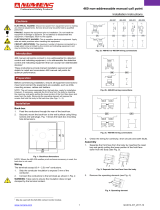
3-2. Installing Welding Power Source Onto Rack
1 Bracket
Remove user-supplied bolt or lock
if applicable.
2 Securing Bolts
Loosen.
3 Front Bracket
Swing end near rack center away
from rack.
4 Rear Bracket
5 Securing Bracket
Place welding power source on
rack so rear is against rear bracket
and securing bracket is centered
between welding power source
feet.
Swing front bracket back into
position.
Tighten securing bolts.
Reinstall user-supplied bolt or lock
if applicable.
6 Weld Cable Hanger
Ref. ST-151 267-B / S-0548 / ST-151 268-A
6
1
3
2
4
5
As Shipped
In Use
Figure 3-2. Welding Power Source Installation

OM-813 Page 3
3-3. Welding Power Source Input Power Connections
WARNING
ELECTRIC SHOCK can kill.
• Do not touch live electrical parts.
• Turn Off welding power source, and disconnect input power to rack before inspecting or installing.
• Have only qualified persons install unit.
• Installation must meet National Electrical Code and all other codes.
swarn3.1* 2/93
When installing conductors from the welding power source, torque the Power
circuit breaker terminals and grounding terminal to 40 in-lbs (4.5 N·m).
NOTE
Have only qualified persons make
this installation.
1 Control Box
2 Access Door
Open access door with same number
as welding power source location.
3 Welding Power Source Input
Power Cord
Route input power cord from units on
upper rack around rear of control box.
4 Strain Relief Connector
Insert input power cord through strain
relief into entry hole for opened ac-
cess door.
5 Grounding Conductor – Green
Or Green With Yellow Stripe(s)
6 Input Conductors
7 Power Circuit Breaker
Terminals
8 Grounding Terminal
Install input conductors from welding
power source to Power circuit
breaker.
Install grounding conductor to
grounding terminal.
Close and secure access door.
Ref. ST-151 267-B / ST-151 269-B
1
2
5
8
4
3
6
7
Figure 3-3. Welding Power Source Input Power Connections

OM-813 Page 4
3-4. 120 Volts AC Duplex Receptacles
Ref. ST-152 657 / Ref. ST-154 542
1 120 Volts AC Duplex
Receptacle
2 Receptacle Cover
This rack supplies up to 20 am-
peres of 120 volts ac power at each
duplex receptacle.
2
1
Figure 3-4. Connecting To 120 Volts AC Duplex Receptacle
Table 3-1. Weld Cable Size*
Total Cable (Copper) Length In Weld Circuit Not Exceeding
100 ft (30 m) Or Less
150 ft
(45 m)
200 ft
(60 m)
250 ft
(70 m)
300 ft
(90 m)
350 ft
(105 m)
400 ft
(120 m)
Welding
Amperes
10 To 60%
Duty Cycle
60 Thru 100%
Duty Cycle
10 Thru 100% Duty Cycle
100 4 4 4 3 2 1 1/0 1/0
150 3 3 2 1 1/0 2/0 3/0 3/0
200 3 2 1 1/0 2/0 3/0 4/0 4/0
250 2 1 1/0 2/0 3/0 4/0 2-2/0 2-2/0
300 1 1/0 2/0 3/0 4/0 2-2/0 2-3/0 2-3/0
350 1/0 2/0 3/0 4/0 2-2/0 2-3/0 2-3/0 2-4/0
400 1/0 2/0 3/0 4/0 2-2/0 2-3/0 2-4/0 2-4/0
500 2/0 3/0 4/0 2-2/0 2-3/0 2-4/0 3-3/0 3-3/0
600 3/0 4/0 2-2/0 2-3/0 2-4/0 3-3/0 3-4/0 3-4/0
700 4/0 2-2/0 2-3/0 2-4/0 3-3/0 3-4/0 3-4/0 4-4/0
800 4/0 2-2/0 2-3/0 2-4/0 3-4/0 3-4/0 4-4/0 4-4/0
900 2-2/0 2-3/0 2-4/0 3-3/0 3-4/0 4-4/0 4-4/0
1000 2-2/0 2-3/0 2-4/0 3-3/0 4-3/0 4-4/0
1250 2-3/0 2-4/0 3-3/0 4-3/0 4-4/0
1500 2-4/0 3-3/0 3-4/0 4-4/0
1750 750 1000 2-750 2-1000 2-1000
2000 750 1000 2-750 2-1000
*Weld cable size (AWG) is based on either a 4 volts or less drop or a current density of at least 300 circular mils per ampere. S-0007-D

OM-813 Page 5
3-5. Common Work Connections
ELECTRIC SHOCK can kill.
• Do not touch live electrical parts.
• Turn Off welding power sources by placing Power
circuit breakers in the Off position before making any
weld output connections.
• Do not connect welding output of different polarities
to the same structure.
• See ANSI Z49.1 and OSHA Title 29, Chapter XVII,
Part 1910, Subpart Q (addresses at beginning of
manual).
• Do not handle or come in contact with two live
electrodes at the same time.
ARCING can burn skin or damage
electrical equipment.
• Do not change position of the welding cable
connectors while welding.
• Be sure the connectors are secure in receptacles
before welding.
INADEQUATE WORK CABLE
CONNECTIONS can cause serious
damage to input power service and
create a hazardous condition.
• Connect an electrical cable of adequate size
between the isolated terminal and the workpiece
whenever any welding power sources are
connected to the isolated terminal.
WARNING
The following procedure is for
Electrode Positive welding
connections.
1 Positive (+) Weld Output
Cables
Determine cable lengths and sizes
according to welding power source
Owner’s Manual.
2 Isolated Terminal
3 Negative (–) Weld Output
Cables
Determine cable sizes according to
welding power source Owner’s
Manual. Cable must reach from
negative (–) output receptacle to
isolated terminal.
4 Common Negative (–) Weld
Output Cable
Cable must be able to carry com-
bined weld output of all welding
power sources using common work
connections. Use Table 3-1 to se-
lect proper cable size.
5 Terminal Lugs
Use lugs of proper amperage ca-
pacity and hole size for connecting
to isolated terminal.
For Electrode Negative, reverse
cable connections. Positive (+)
weld output cables connect to iso-
lated terminal, negative (–) weld
output cables go to electrode. Com-
mon weld output cable is positive.
ST-154 544-A / Ref. ST-154 540-A
1
GTAW
GMAW
SMAW
GTAW
GMAW
SMAW
3
1
42
2
3
5
4
Figure 3-5. Common Work Connections

OM-813 Page 6
3-6. Paralleling Welding Power Sources For SMAW
ELECTRIC SHOCK can kill.
• Do not touch live electrical parts.
• Turn Off welding power sources by placing Power
circuit breakers in the Off position before making any
weld output connections.
• Do not connect welding output of different polarities
to the same structure.
• See ANSI Z49.1 and OSHA Title 29, Chapter XVII,
Part 1910, Subpart Q (addresses at beginning of
manual).
• Do not handle or come in contact with two live
electrodes at the same time.
UNDERSIZED WELDING CABLES can
cause fire.
• Use single cables of adequate capacity to carry the
total combined amperage of the paralleled welding
power sources.
ARCING can burn skin or damage
electrical equipment.
• Do not change position of the welding cable
connectors while welding.
• Be sure the connectors are secure in receptacles
before welding.
INADEQUATE WORK CABLE
CONNECTIONS can cause serious
damage to input power service and
create a hazardous condition.
• Connect an electrical cable of adequate size
between the isolated terminal and the workpiece
whenever any welding power sources are
connected to the isolated terminal.
WARNING
Set the Amperage/Voltage control
on all paralleled welding power
sources to the same value. The iso-
lated terminal may be used as a
common connection point if no
other connections are made to it.
The procedure shown is for
Electrode Positive welding
connections.
1 Weld Output Cables
Determine cable sizes according to
welding power source Owner’s
Manual. Cables must reach cable
connection point. Cables con-
nected together must be the same
polarity.
2 Connection Point
Cover with proper insulating
material after making connections.
3 Terminal Lugs
Use lugs of proper amperage
capacity and hole size for connec-
tion.
4 Common Weld Output Cable
Cable must be able to carry com-
bined weld output of all welding
power sources connected in paral-
lel. Use Table 3-1 to select proper
cable size.
For Electrode Negative, reverse
cable connections. Positive (+)
weld output cables connect to work,
negative (–) weld output cables go
to electrode.
ST-154 543-B / Ref. ST-154 540-A
1
1
2
SMAW
+
–
3
4
Securely cover connection
with proper insulating
material.
1
4
4
Figure 3-6. Paralleling Welding Power Sources For SMAW

OM-813 Page 7
3-7. Connecting Input Power To Rack
WARNING
ELECTRIC SHOCK can kill.
• Do not touch live electrical parts.
• Turn Off welding power sources before inspecting or installing rack.
• Have only qualified persons install rack.
• Installation must meet National Electrical Code and all other codes.
swarn3.1* 2/93
Have only qualified persons make
this installation.
1 Rear Control Box Center
2 Access Panel
Remove access panel.
3 Line Disconnect Device Of
Proper Rating
4 Input Conductors
5 Grounding Conductor
Select size and length using
Table 3-2. Conductors must be
able to carry the combined amper-
age draw of all welding power
sources mounted on the rack. Con-
ductor insulation must comply with
national, state, and local electrical
codes. Use lugs of proper amper-
age capacity and correct hole size.
6 User-Supplied Strain Relief
Connector
Insert conductors through strain
relief.
7 Input Terminal Block
8 Line Terminals
9 Ground Terminal
Connect grounding conductor to
ground terminal first. Then connect
input conductors to line terminals.
Reinstall access panel.
Install grounding conductor and in-
put conductors in conduit or equiv-
alent to deenergized line discon-
nect device.
Connect grounding conductor first,
then line input conductors.
Be sure grounding conductor goes
to an earth ground.
10 Overcurrent Protection
Select type and size using
Table 3-2. Install into deenergized
line disconnect device (fused
disconnect switch shown).
1 2
7
8
4
6 95
3
10
ST-151 270-C
5
Figure 3-7. Input Power Connections

OM-813 Page 8
Table 3-2. Electrical Service Guide
Input Voltage
230 460 575
Max Recommended Standard Fuse Or Circuit
Breaker Rating In Amperes
500 250 200
Min Input Conductor Size In AWG/Kcmil
350 1/0 1
Max Recommended Input Conductor Length In
Feet (Meters)
240 (73) 415 (126) 557 (170)
Min Grounding Conductor Size In AWG/Kcmil
2 4 6
Reference: 1993 National Electrical Code (NEC). S-0092J
SECTION 4 – MAINTENANCE & TROUBLESHOOTING
ELECTRIC SHOCK can kill.
• Do not touch live electrical parts.
• Turn Off welding power sources, and disconnect input power to rack before inspecting, maintaining, or servicing.
Maintenance to be performed only by qualified persons.
WARNING
4-1. Routine Maintenance
6 Months
Turn Off all power before maintaining.
ST-151 267-B
3 Months
Clean
And
Tighten
Weld
Terminal
(If Used)
Replace
Unreadable
Labels
Tape Or
Replace
Cracked
Cables
OR
During Heavy Service,
Clean Monthly
Blow Out
Or
Vacuum
Inside
Figure 4-1. Maintenance Schedule

OM-813 Page 9
4-2. Overload Protection
READ SAFETY BLOCKS at start of
Section 4 before proceeding.
WARNING
A. Fuses
CAUTION
STATIC ELECTRICITY can damage parts on circuit boards.
• Put on grounded wrist strap BEFORE handling boards or parts.
fwarn5.1* 9/91
Turn Off welding power sources and
disconnect input power to rack.
1 Rear Control Box Center
2 Access Panel
Remove rear access panel to left of
center to check and replace fuses.
Use proper tool when removing
fuses.
230/460 Volt Input Models:
3 Fuse F1 (See Parts List For
Rating)
4 Fuse F2 (See Parts List For
Rating)
Fuses F1 and F2 protect the auxiliary
power transformer T2 from overload.
F1 protects when the rack is con-
nected to 230 volt input power and F2
protects when the rack is connected
to 460 volt input power.
5 Fuse F3 (See Parts List For
Rating)
Fuse F3 protects the control circuitry
that links the duplex receptacles for
230 or 460 volt input power.
460/575 Volt Input Models:
6 Fuse F1 (See Parts List For
Rating)
Fuse F1 protect the auxiliary power
transformer T2 from overload.
7 Fuse F2 (See Parts List For
Rating)
Fuse F2 protects the control circuitry
that links the duplex receptacles for
460 or 575 volt input power.
Both Models:
If a fuse opens, equipment connected
to either of the duplex receptacles
shuts down.
Reinstall rear access panel.
ST-154 545-A / ST-157 883-A
12
543
76
Both Models
230/460 Volt Input Models
460/575 Volt Input Models
Figure 4-2. Fuse Locations

OM-813 Page 10
B. Circuit Breakers
1 Power Circuit Breakers
CB1-CB8
Each Power circuit breaker CB1
through CB8 protects the welding
power source connected to it from
overload.
If a Power circuit breaker opens,
the matching welding power source
would shut down. Manually reset
the Power circuit breaker.
2 Circuit Breaker CB9
3 Circuit Breaker CB10
Circuit breakers CB9 and CB10
protect auxiliary power transformer
T2 from overload.
If CB9 or CB10 opens, the duplex
receptacle beneath the circuit
breaker does not work. Manually
reset CB9 or CB10.
Ref. ST-151 267-B / Ref. ST-154 542 / Ref. ST-152 657 / Ref. ST-151 269-A
2
1
3
Figure 4-3. Circuit Breaker Locations

OM-813 Page 11
4-3. Troubleshooting
ELECTRIC SHOCK can kill.
• Do not touch live electrical parts.
• Turn Off welding power sources, and disconnect input power to rack before inspecting, maintaining, or servicing.
Troubleshooting to be performed only by qualified persons.
WARNING
Table 4-1. Rack Trouble
Trouble Remedy Section
No weld output from any welding power
sources; units completely inoperative.
Place line disconnect switch in On position. 3-7
Check line fuse(s) and replace if needed. Reset circuit breakers. 3-7
Check for proper input power connections to rack. 3-7
No weld output from one welding power
source.
Place applicable Power circuit breaker in On position. 4-2
Check for proper input power connections to welding power source. 3-3
Check applicable welding power source according to its manual.
No 120 volt ac output from either duplex
receptacle.
Check applicable fuses F1-F3 and replace if needed. 4-2A
No 120 volt ac output from one duplex re-
ceptacle.
Reset applicable circuit breaker CB9 or CB10. 4-2B

OM-813 Page 12
SECTION 5 – ELECTRICAL DIAGRAMS
SB-153 320
Figure 5-1. Circuit Diagram For 230/460 Volt Input Model Rack Control Box
SB-156 069
Figure 5-2. Circuit Diagram For 460/575 Volt Input Model Rack Control Box

OM-813 Page 13
Figure 5-3. Wiring Diagram For 230/460 Volt Input Model Rack Control Box
SC-153 321

OM-813 Page 14
Figure 5-4. Wiring Diagram For 460/575 Volt Input Model Rack Control Box
SC-156 071
/