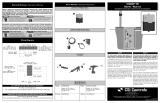
Installing the Transmitter and Float Switches
The RK Series™ Single Phase control panel operates with one 4-20mA
submersible level transmitter and one or two backup fl oat switches.
Mounting the Control Panel
1
Ensure all power is turned OFF before installing
fl oats in tank. Failure to do so could result in
serious or fatal shock.
If the distance to the control panel exceeds the length of the fl oat
switch cords or the pump power cord, splicing in a liquid-tight
junction box will be required. For outdoor or wet installation, we
recommend a UL Type 4X junction box.
2
2
If the fl oats are not properly mounted and connected in the correct
order, the pumps will not function properly.
Floats require free range of motion.
This RK Series™ control panel uses a 4-20mA level transmitter.
Hand Operation - If the level is above the “Pump Off Setpnt” and
the Low level back up Float Switch is UP, press the “HAND” switch
momentarily and the pump will run until the level drops below the
“Pump Off Setpnt” or the fl oat opens, or press the “HAND” switch
again to stop the pump. For Time dose operation, the HAND pump
operation is limited by the “Pump On Time”.
Press and hold the “HAND” switch to operate the pump if the Low
Level Backup fl oat is OPEN or the level is below the “Pump Off Setpnt”.
Off Operation - Turn corresponding breaker off to be in Off operation.
Auto Operation - In timed dose mode, the timer controls the pump
ON and OFF time as long as the well level is above the “Lead ON
Setpoint” and the Low Level backup fl oat is CLOSED. If the level
drops below the “Off Setpoint”, the timer will stop the pump and end
the dose prematurely.
In demand mode, the level transmitter controls the pumps. The lead
pump will start when the level rises above the “Lead ON Setpoint”
and run until the level drops below “Off Setpoint”.
Power and Blown Fuse Indicators
The Control and Alarm circuits each have a green LED indicator when
power is applied.
If a fuse is blown, the red fuse blown LED indicator above the fuse
will turn ON.
Wiring the Control Panel
1Determine conduit entrance locations on control panel as shown.
Check local codes and wiring diagram on the inside cover of the
panel for the number of power circuits required.
Be sure the pump power voltage and phase are the same as
the pump motor being installed.
Use of separate pump and control/alarm power sources is
recommended.
3Verify correct operation of control panel after installation is
complete.
2Connect the following wires to the proper terminal positions:
• incoming power for each pump circuit
• incoming power for control/alarm circuit
• pump 1
• pump 2 (Duplex)
• backup fl oat switches
• 4-20mA transmitter
Type 4X conduit must be used to maintain a Type 4X rating of
the control panel.
CAUTION!
You must use conduit sealant to prevent moisture or gases
from entering the panel.
Operations
Do not install cord under hose
clamp.
Tighten
the clamp.
Hose clamp is 18-8 stainless
steel. Contact your CSI Controls
supplier for replacements.
Make sure hose clamp band
does not interfere with fl oat
operation. cable
weight
fl oat
switch
tether length
minimum 3.5 inches
Replace product immediately if switch, cable
weight or cable is damaged or cracked.
1 inch (2.5 cm)
minimum from
bottom of tank or
from sludge
0 inch (0 cm) liquid
level measured
from approximately
this point
4 inch (10.2 cm)
minimum set level
Caution: Do not overtighten clamp or tie straps.
WARNING: To prevent erroneous measurements, do not allow the sensor
diaphragm to come into contact with solid objects or sludge. Do not use level
measurements less than 4” (10.2 cm) for control or alarm purposes (dead
band).
Tie Straps
2-Float & Transmitter Installation WARNING: DO NOT support
transmitter by the cable.
WARNING: DO NOT kink or place
cable under hose clamp. Doing so
may cause failure.
Mount control panel using integrated mounting fl ange.
CAUTION!


