Mitsubishi Electric SEZ-M25 User manual

Category
Split-system air conditioners
Type
User manual
Packaged Air-Conditioners
INDOOR UNIT
SEZ-M25,M35,M50,M60,M71DAL
INSTALLATION MANUAL
For safe and correct use, please read this installation manual thoroughly before installing the air-conditioner unit.
FOR INSTALLER
English
<ORIGINAL>
2
3
[Fig. 3-1-1]
3.1
[Fig. 3-1-3]
P50
R
777
450
100~200
450475
70050
Min. 300 mm
(Viewed from the direction of the arrow B)
[Fig. 3-1-4]
Electric box Intake air
Ceiling Bottom of indoor unit
Ceiling beam Access door 3
Access door 2 (450 mm x 450 mm) Access door 4
Access door 1 (450 mm x 450 mm)
Maintenance access space
Supply air
(mm)
Model P Q R S
SEZ-M25 700 50~150 800 1300
SEZ-M35, 50 900 150~250 1000 1500
SEZ-M60, 71 1100 250~350 1200 1700
777
S
50
50 P
700
Min. 300 mm
(Viewed from the direction of the arrow B)
[Fig. 3-1-5]
700
450
475 450
Q
50~150
450
450
100~200
Min. 300 mm
(Viewed from the direction of the arrow A)
P
[Fig. 3-1-2] (Unit: mm)
Min. 300 mm
Min. 2500 mm
Min. 10 mm
A
H
AC
D
G
B
B
Min. 20 mm
Min.10 mm
H
AC
G
JB
Min. 2500 mm
3
4
[Fig. 4-1]
5
YX
LW
Z
Center of gravity
5.1
Nuts (field supply)
Washers (accessory)
M10 hanging bolt (field supply)
[Fig. 5-2]
Unit body
Lifting machine
[Fig. 5-1]
4
6
[Fig. 6-1]
ØB
ØA
Indoor unit
Outdoor unit
90˚
A
[Fig. 6-9]
20
20
20
20
[Fig. 6-10]
[Fig. 6-3]
[Fig. 6-6]
[Fig. 6-4] [Fig. 6-5]
Flare nut
Copper tube
Burr
Copper tube/pipe
Spare reamer
Pipe cutter
[Fig. 6-7]
[Fig. 6-8]
Downward slope 1/100 or more
Connection dia. R1 external thread
Indoor unit
Collective piping
Maximize this length to approx. 10 cm
Flaring tool
Die
Copper tube
Flare nut
Yoke
Smooth all around
Inside is shining without
any scratches
Even length all around
Too much
Tilted
Scratch on
flared plane
Cracked
Uneven
Bad examples
6.1
6.2
Copper tubes
ⓑGood
No good
Tilted
Uneven
Burred
6.3
6.5
5 25
Indoor unit
Pipe cover (short) (accessory)
Tie band (accessory)
Band fixing part
Insertion margin
Drain hose (accessory)
Drain pipe (O.D. ø32 PVC TUBE, field supply)
Insulating material (field supply)
Max.145 ± 5 mm
[Fig. 6-11]
Pipe cover (small) (accessory)
Caution:
Pull out the thermal insulation on the refrigerant piping at
the site, insert the flare nut to flare the end, and replace the
insulation in its original position.
Take care to ensure that condensation does not form on
exposed copper piping.
Liquid end of refrigerant piping
Gas end of refrigerant piping
Site refrigerant piping
Main body
Pipe cover (large) (accessory)
Thermal insulation (field supply)
Pull
Flare nut
Return to original position
Ensure that there is no gap here
Plate on main body
Band (accessory)
Ensure that there is no gap here. Place join upwards.
Model A B
SEZ-M25, 35 9.52 6.35
SEZ-M50 12.7 6.35
SEZ-M60 15.88 6.35
SEZ-M71 15.88 9.52
5
S3
S2
S1
S3
S2S1
CN90
Indoor unit
Outdoor unit
Signal receiving unit
Wireless remote controller
Main switch/fuse
Grounding
[Fig. 8-1]
[Fig. 8-2-1]
S3
S3
S2
S1
S2S1
For Power supply
For Power
supply
Use PG bushing to keep the weight of the cable and external force from being
applied to the power supply terminal connector. Use a cable tie to secure the cable.
Indoor/outdoor unit connecting wire
Tensile force
Use ordinary bushing
Signal receiving unit wiring
Terminal bed for power source and indoor transmission
Indoor/outdoor unit connecting wire
Connecting the signal receiving unit
Connect the signal receiving unit to the CN90 (Connect to the wireless remote
controller board) on the indoor unit using the supplied remote controller wire.
Connect the signal receiving units to all the indoor units.
Terminal bed box
Knockout hole
Remove
Screw holding cover (2pcs)
Cover
[Fig. 8-2-3] [Fig. 8-2-4]
[Fig. 8-2-2]
[Fig. 7-1]
Air inlet
Air outlet
Access door
Ceiling surface
Canvas duct
Air filter
Inlet grille
7
8.2
88.1
6
Attach the remote controller holder to the desired location using two tapping screws.
Place the lower end of the controller into the holder.
Remote controller
Wall
Display panel
Receiver
The signal can travel up to approximately 7 meters (in a straight line) within 45 degrees to both
right and left of the center line of the receiver.
[Fig. 8-4]
8.3
[Fig. 8-3]
Indoor terminal block
Earth wire (green/yellow)
Indoor/outdoor unit connecting wire
3-core 1.5 mm2 or more
Outdoor terminal block
Power supply cord
Indoor controller board
Connecting cable
Cable 3-core 1.5 mm2, in conformity
with Design 245 IEC 57.
Indoor terminal block
CN90
LN
Indoor terminal block
Indoor/outdoor unit
connecting wire
3-core 1.5 mm2 or
more
Outdoor terminal block
Earth wire (green/yellow)
Power supply cord
Outdoor terminal block
Always install an earth wire (1-core 1.5
mm2) longer than other cables
Signal receiving unit cable (accessory)
(wire length : 5 m)
Signal receiving unit
Power supply cord
Indoor controller
board
88.2
J41
J42
JP1
JP2
JP3
CN90 CN4F CN44 CN20(Red) CNMF
SW1 SW2 CN32
CN41CN51
ON OFF
SWE
CN2L CN22(Blue)
CNP
(Blue)
CN3C(Blue)
CN01
(Black)
CN90: Connector for remote controller wire connection
Controller circuit board on the indoor unit (reference)
IC
OC(00)
CN90
TB1
TB4
Standard 1:1
[Fig. 8-5]
[Fig. 8-6]
IC IC IC IC
CN90 CN90 CN90 CN90
Pair number: 0
[Fig. 8-7]
IC
CN90
IC
CN90
IC IC IC IC
CN90 CN90 CN90 CN90
[Fig. 8-9][Fig. 8-8]
Pair number: 0 Pair number: 1 Pair number: 2 Pair number: 3
Pair number: 0 Pair number: 0 Pair number: 0 Pair number: 0
Pair number: 0 Pair number: 0
Pair number: 0
Outdoor unit
Refrigerant address
Indoor unit
Signal receiving unit
Indoor/outdoor wiring
Signal receiving unit wiring
ON
OFF
STAND
BY COOL HEAT
7
88.3
Signal receiving unit external
Center of Switch box
Switch box
Installation pitch
6.5 mm (1/4 inch)
70 mm (2 - 3/4 inch)
83.5 ± 0.4 mm (3 - 9/32 inch)
Protrusion (pillar, etc)
[Fig. 8-11]
Remote controller wire
Hole (drill a hole on the ceiling to pass the remote controller wire.)
Signal Receiving Unit
Ceiling cassette type, Ceiling concealed type
[Fig. 8-12]
Fix tightly with tape.
Remote controller wire
Order wire
[Fig. 8-13]
Insert the minus screwdriver toward the
arrow pointed and wrench it to remove
the cover.
A at screwdriver whose width of blade
is between 4 and 7 mm (5/32 - 9/32 inch)
must be used.
[Fig. 8-14]
Indoor unit
Hang the cover to the upper hooks (2 places).
Mount the cover to the lower case
Cross-section of upper hooks
[Fig. 8-10]
[Fig. 8-15]
When using the switch box When installing directly on the wall
150 mm (5 - 15/16 inch)
Remote controller wire (Accessory)
Wiring pipe
Locknut
Seal around here with putty
Remote controller wire
Seal around here with putty
Bushing
Switch box
Seal around here with putty
Wall
8
CHECK CHECK
CHECKCHECK
ON/OFF TEMP
FAN
VANE
TEST RUN
AUTO STOP
AUTO START
h
min
LOUVER
MODE
CHECK
RESETSET CLOCK
CHECK
88.3
[Fig. 8-16]
[Fig. 8-17]
Thin-wall portion
Bottom case
Remote controller wire
Conducting wire
[Fig. 8-18]
Screw (M4 × 30)
* When installing the lower case directly on the wall or the ceiling,
use wood screws.
Insert the minus screwdriver toward the
arrow pointed and wrench it to remove the
cover.
A at screwdriver whose width of blade
is between 4 and 7 mm (5/32 - 9/32 inch)
must be used.
[Fig. 8-19]
Hang the cover to the upper hooks (2 places).
Mount the cover to the lower case
Cross-section of upper hooks
Hour button
Minute button
TEMP button
TEMP button
ON/OFF button
CHECK button
[Fig.8-20]
8.4
9
9
[Fig. 9-1]
TEST RUN button
MODE button
FAN button
VANE button
9.1
10
[Fig. 10-1]
Indoor unit
Union
Liquid pipe
Gas pipe
Stop valve
Outdoor unit
Refrigerant gas cylinder operating valve
Refrigerant gas cylinder for R32/R410A with
siphon
Refrigerant (liquid)
Electronic scale for refrigerant charging
Charge hose (for R32/R410A)
Gauge manifold valve (for R32/R410A)
Service port
10.1
ON/OFF TEMP
FAN
VANE
TEST RUN
AUTO STOP
AUTO START
h
min
LOUVER
MODE
CHECK
RESETSET CLOCK
TEST RUN
10
1. Safety precautions
Before installing the unit, make sure you read all the “Safety Precautions”.
The “Safety Precautions” provide very important points regarding safety. Make sure you follow them.
Please report to or take consent by the supply authority before connection to the system.
MEANINGS OF SYMBOLS ON THE UNIT
WARNING
(Risk of re)
This symbol is only for R32 refrigerant. The type of the refrigerant used is written on the nameplate on the outdoor unit.
R32 refrigerant is ammable. If the refrigerant leaks, or comes in contact with re or parts that generate heat, it may create harmful gas
and pose a risk of re.
Read the OPERATION MANUAL carefully before operation.
Service personnel are required to carefully read the OPERATION MANUAL and INSTALLATION MANUAL before operation.
Further information is available in the OPERATION MANUAL, INSTALLATION MANUAL, and the like.
Please report to or take consent by the supply authority before connection
to the system.
Be sure to read “Safety precautions” before installing the air conditioner.
Be sure to observe the cautions specied here as they include important
items related to safety.
The indications and meanings are as follows.
Warning:
Could lead to death, serious injury, etc.
Caution:
Could lead to serious injury in particular environments when operated
incorrectly.
After reading this manual, be sure to keep it together with the instruction
manual in a handy place on the customers site.
Symbols put on the unit
: Indicates an action that must be avoided.
: Indicates that important instructions must be followed.
: Indicates a part which must be grounded.
: Indicates that caution should be taken with rotating parts.
: Indicates that the main switch must be turned off before servicing.
: Beware of electric shock.
: Beware of hot surface.
Warning:
Carefully read the labels afxed to the main unit.
Warning:
Do not use refrigerant other than the type indicated in the manuals
provided with the unit and on the nameplate.
- Doing so may cause the unit or pipes to burst, or result in explosion or re
during use, during repair, or at the time of disposal of the unit.
- It may also be in violation of applicable laws.
- MITSUBISHI ELECTRIC CORPORATION cannot be held responsible for
malfunctions or accidents resulting from the use of the wrong type of
refrigerant.
When handling this product, always wear protective equipment.
EG: Gloves, full arm protection namely boiler suit, and safety glasses.
- Improper handling may result in injury.
Do not install it by yourself (customer).
Incomplete installation could cause injury due to re, electric shock, the
unit falling or leakage of water. Consult the dealer from whom you
purchased the unit or special installer.
Install the unit securely in a place which can bear the weight of the unit.
When installed in an insufcient strong place, the unit could fall causing
injured.
Use the specied wires to connect the indoor and outdoor units securely
and attach the wires rmly to the terminal board connecting sections so
the stress of the wires is not applied to the sections.
Incomplete connecting and xing could cause re.
Do not use intermediate connection of the power cord or the extension
cord and do not connect many devices to one AC outlet.
It could cause a re or an electric shock due to defective contact, defective
insulation, exceeding the permissible current, etc.
Check that the refrigerant gas does not leak after installation has
completed.
Perform the installation securely referring to the installation manual.
Incomplete installation could cause a personal injury due to re, electric
shock, the unit falling or leakage of water.
Perform electrical work according to the installation manual and be sure to
use an exclusive circuit.
If the capacity of the power circuit is insufcient or there is incomplete
electrical work, it could result in a re or an electric shock.
Attach the electrical part cover to the indoor unit and the service panel to
the outdoor unit securely.
If the electrical part cover in the indoor unit and/or the service panel in the
outdoor unit are not attached securely, it could result in a re or an electric
shock due to dust, water, etc.
Be sure to use the part provided or specied parts for the installation work.
The use of defective parts could cause an injury or leakage of water due to
a re, an electric shock, the unit falling, etc.
Ventilate the room if refrigerant leaks during operation.
If the refrigerant comes in contact with a ame, poisonous gases will be
released.
If the supply cord is damaged, it must be replaced by the manufacturer, its
service agent or similarly qualied persons in order to avoid a hazard.
This appliance is not intended for use by persons (including children) with
reduced physical, sensory or mental capabilities, or lack of experience and
knowledge, unless they have been given supervision or instruction
concerning use of the appliance by a person responsible for their safety.
Children should be supervised to ensure that they do not play with the
appliance.
The installer and system specialist shall secure safety against leakage
according to local regulation or standards.
- The instructions in this manual may be applicable if local regulation are not
available.
Pay a special attention to the place, such as a basement, etc. where
refrigeration gas can stay, since refrigeration is heavier than the air.
This appliance is intended to be used by expert or trained users in shops,
in light industry and on farms, or for commercial use by lay persons.
When installing, relocating, or servicing the air conditioner, use only the
specied refrigerant written on the outdoor unit to charge the refrigerant
lines. Do not mix the refrigerant with any other refrigerant, and do not allow
air to remain in the lines.
- If air is mixed with the refrigerant, then it may cause abnormal high pressure in
the refrigerant lines, resulting in an explosion and other hazards.
- The use of any refrigerant other than that specied for the system will cause
mechanical failure, system malfunction, or unit breakdown. In the worst case,
this could lead to a serious impediment to securing product safety.
- It may also be in violation of applicable laws.
- MITSUBISHI ELECTRIC CORPORATION cannot be held responsible for
malfunctions or accidents resulting from the use of the wrong type of refrigerant.
Contents
1. Safety precautions ........................................................................................10
2. Selecting the installation location .................................................................12
3. Selecting an installation site & Accessories.................................................. 12
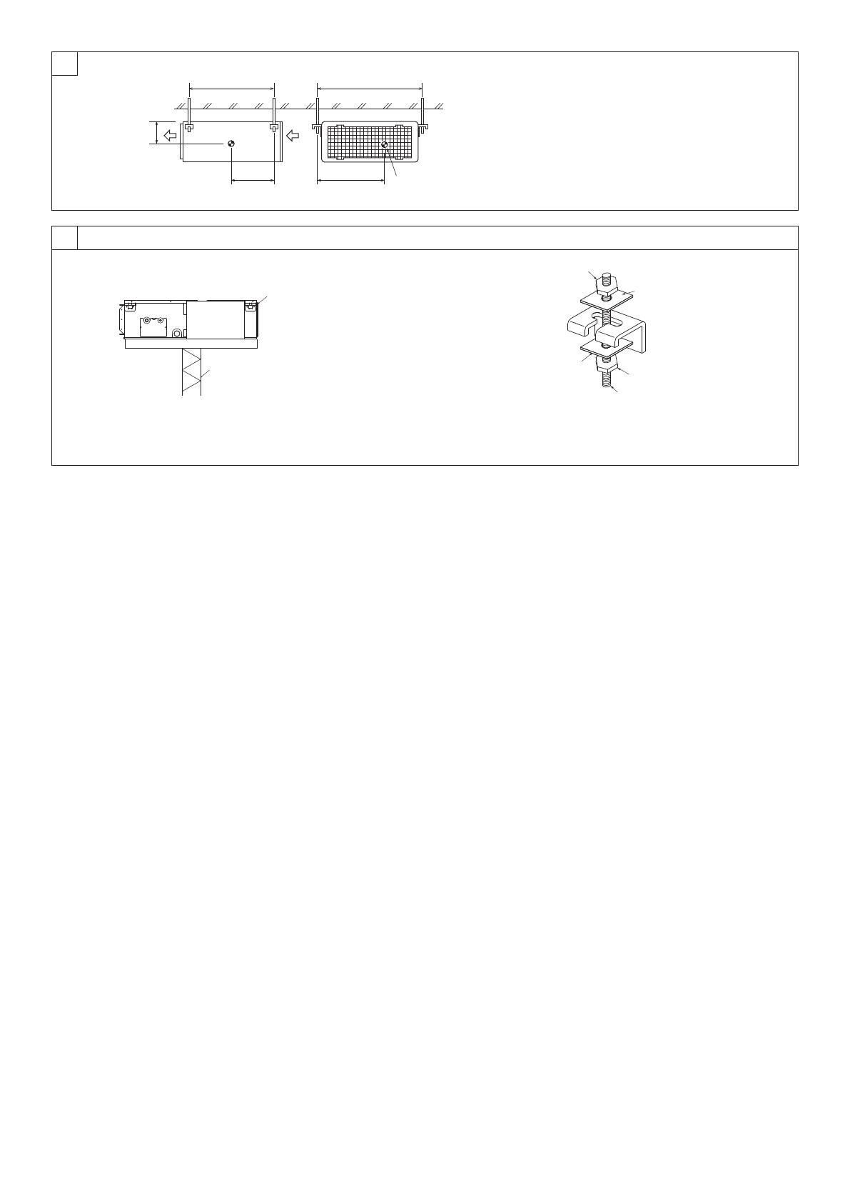
4. Fixing hanging bolts......................................................................................13
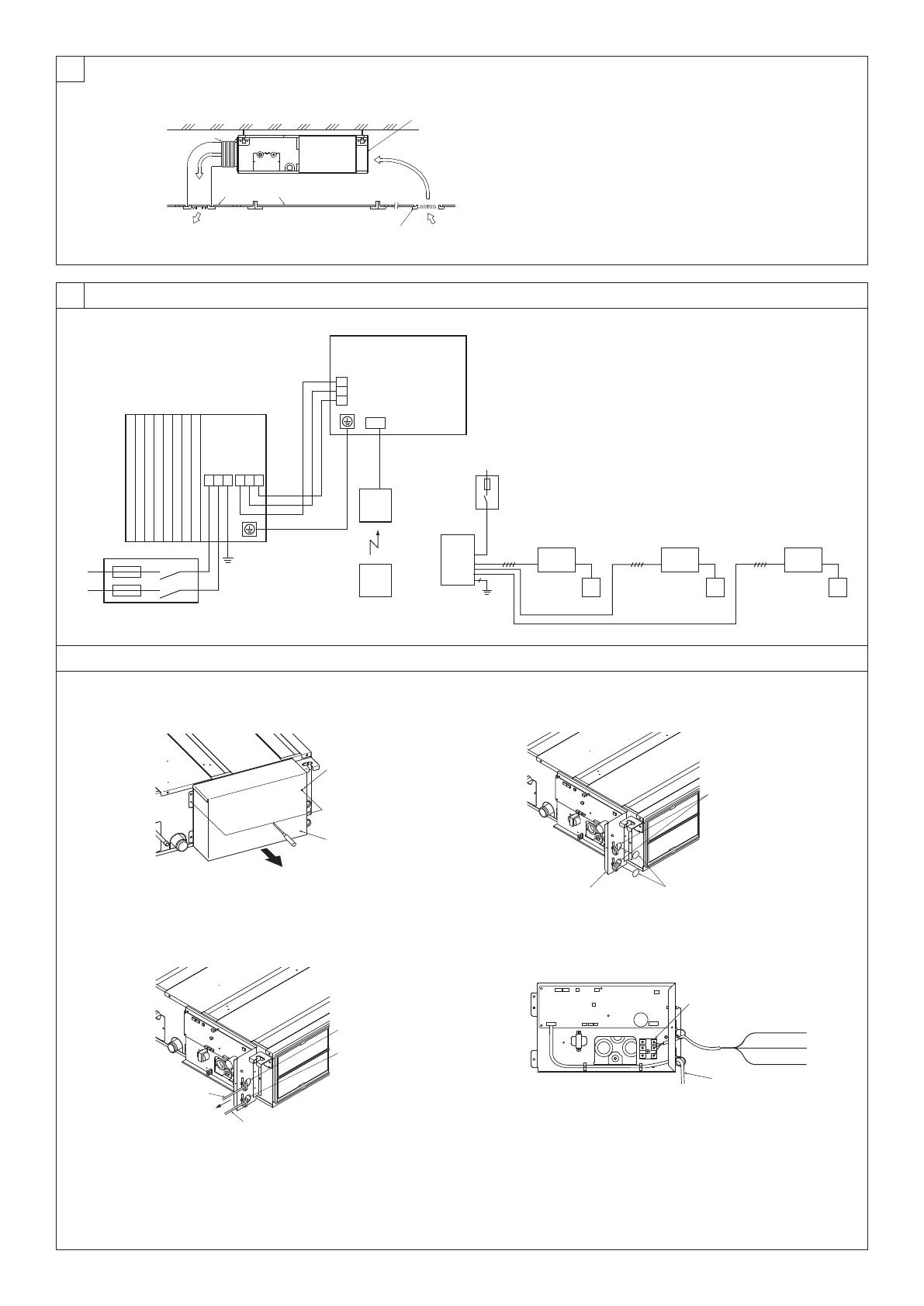
5. Installing the unit...........................................................................................13
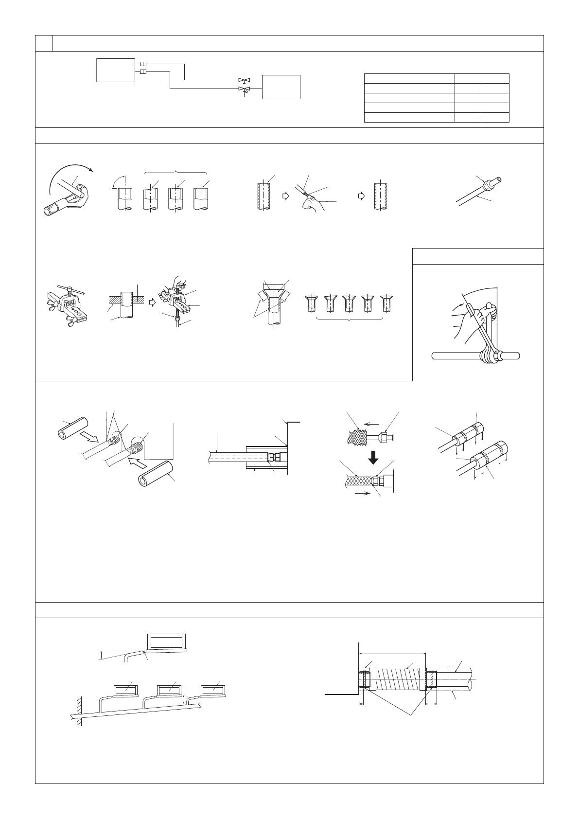
6. Refrigerant piping work.................................................................................14
7. Duct work......................................................................................................15
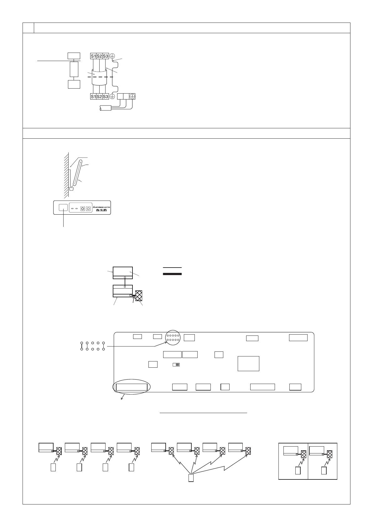
8. Electrical work ..............................................................................................16
9. Test run .........................................................................................................18
10. Maintenance ............................................................................................... 20
This Installation Manual describes only for the indoor unit and the connected
outdoor unit of SUZ series.
If the connected outdoor unit is MXZ series, refer to the Installation Manual for
MXZ series.
11
1. Safety precautions
This indoor unit should be installed in a room which is equal to or larger
than the oor space specied in the outdoor unit installation manual. Refer
to the outdoor unit installation manual.
Only use means recommended by the manufacturer to accelerate the
defrosting process or to clean.
This indoor unit shall be stored in a room that has no continuously-
operating ignition device such as open ame, gas appliance, or electrical
heater.
Do not pierce a hole in or burn this indoor unit or refrigerant lines.
Be aware that the refrigerant may be odour-free.
Pipe-work shall be protected from physical damage.
The installation of pipe-work shall be kept to a minimum.
Compliance with national gas regulations shall be observed.
Keep any required ventilation openings clear of obstruction.
Do not use low temperature solder alloy when brazing the refrigerant pipes.
When performing brazing work, be sure to ventilate the room sufciently.
Make sure that there are no hazardous or ammable materials nearby.
When performing the work in a closed room, small room, or similar
location, make sure that there are no refrigerant leaks before performing
the work. If refrigerant leaks and accumulates, it may ignite or poisonous
gases may be released.
For installation and relocation work, follow the instructions in the
installation manual and use tools and pipe components specically made
for using with refrigerant specied in the outdoor unit installation manual.
Caution:
Perform grounding.
Do not connect the ground wire to a gas pipe, water pipe arrester or
telephone ground wire. Defective grounding could cause an electric shock.
Do not install the unit in a place where an inammable gas leaks.
If gas leaks and accumulates in the area surrounding the unit, it could
cause an explosion.
Install a ground leakage breaker depending on the installation place (where
it is humid).
If a ground leakage breaker is not installed, it could cause an electric
shock.
Perform the drainage/piping work securely according to the installation
manual.
If there is a defect in the drainage/piping work, water could drop from the
unit and household goods could be wet and damaged.
Fasten a are nut with a torque wrench as specied in this manual.
When fastened too tight, a are nut may broken after a long period and
cause a leakage of refrigerant.
12
2. Selecting the installation location
2.1. Indoor unit
Where airow is not blocked.
Where cool air spreads over the entire room.
Where it is not exposed to direct sunshine.
At a distance 1 m or more away from your TV and radio (to prevent picture from
being distorted or noise from being generated).
In a place as far away as possible from uorescent and incandescent lights (so
the infrared remote control can operate the air conditioner normally).
Where the air lter can be removed and replaced easily.
Warning:
Mount the indoor unit into a ceiling strong enough to withstand the weight of
the unit.
The indoor models should be installed the ceiling over than 2.5 m from oor.
2.2. Outdoor unit
Where it is not exposed to strong wind.
Where airow is good and dustless.
Where it is not exposed to rain and direct sunshine.
Where neighbours are not annoyed by operation sound or hot air.
Where rigid wall or support is available to prevent the increase of operation
sound or vibration.
Where there is no risk of combustible gas leakage.
When installing the unit at a high level, be sure to x the unit legs.
Where it is at least 3 m away from the antenna of TV set or radio. (Otherwise,
images would be disturbed or noise would be generated.)
Install the unit horizontally.
Caution:
Avoid the following places for installation where air conditioner trouble is
liable to occur.
Where there is too much machine oil.
Salty environment as seaside areas.
Hot-spring areas.
Where sulde gas exists.
Other special atmospheric areas.
3. Selecting an installation site & Accessories
Select a site with sturdy xed surface sufciently durable against the weight of unit.
Before installing unit, the routing to carry in unit to the installation site should be
determined.
Select a site where the unit is not affected by entering air.
Select a site where the ow of supply and return air is not blocked.
Select a site where refrigerant piping can easily be led to the outside.
Select a site which allows the supply air to be distributed fully in room.
Do not install unit at a site with oil splashing or steam in much quantity.
Do not install unit at a site where combustible gas may generate, ow in,
stagnate or leak.
Do not install unit at a site where equipment generating high frequency waves (a
high frequency wave welder for example) is provided.
Do not install unit at a site where re detector is located at the supply air side.
(Fire detector may operate erroneously due to the heated air supplied during
heating operation.)
When special chemical product may scatter around such as site chemical plants
and hospitals, full investigation is required before installing unit. (The plastic
components may be damaged depending on the chemical product applied.)
If the unit is run for long hours when the air above the ceiling is at high
temperature/high humidity (due point above 26 °C), due condensation may be
produced in the indoor unit. When operating the units in this condition, add
insulation material (10-20 mm) to the entire surface of the indoor unit to avoid
due condensation.
3.1. Install the indoor unit on a ceiling strong enough
to sustain its weight
Secure enough access space to allow for the maintenance, inspection, and
replacement of the motor, fan, drain pump, heat exchanger, and electric box in one
of the following ways.
Select an installation site for the indoor unit so that its maintenance access space
will not be obstructed by beams or other objects.
(1) When a space of 300 mm or more is available below the unit between the unit
and the ceiling (Fig. 3-1-1)
Create access door 1 and 2 (450 x 450 mm each) as shown in Fig. 3-1-2.
(Access door 2 is not required if enough space is available below the unit for a
maintenance worker to work in.)
(2) When a space of less than 300 mm is available below the unit between the unit
and the ceiling (At least 20 mm of space should be left below the unit as shown
in Fig. 3-1-3.)
Create access door 1 diagonally below the electric box and access door 3
below the unit as shown in Fig. 3-1-4.
or
Create access door 4 below the electric box and the unit as shown in Fig.
3-1-5.
[Fig. 3-1-1] (P.2)
[Fig. 3-1-2] (Viewed from the direction of the arrow A)(P.2)
[Fig. 3-1-3] (P.2)
[Fig. 3-1-4] (Viewed from the direction of the arrow B)(P.2)
[Fig. 3-1-5] (Viewed from the direction of the arrow B)(P.2)
Electric box Ceiling
Ceiling beam Access door 2 (450 mm x 450 mm)
Access door 1 (450 mm x 450 mm) Maintenance access space
Supply air Intake air
Bottom of indoor unit Access door 3
Access door 4
Warning:
The unit must be securely installed on a structure that can sustain its weight.
If the unit is mounted on an unstable structure, it may fall down causing
injuries.
Warning:
This unit should be installed in rooms which exceed the oor space
specied in outdoor unit installation manual. Refer to outdoor unit
installation manual.
Install the indoor unit at least 2.5 m above oor or ground level. For
appliances not accessible to the general public.
Refrigerant pipes connection shall be accessible for maintenance purpose.
3.2. Securing installation and service space
Select the optimum direction of supply airow according to the conguration of
the room and the installation position.
As the piping and wiring are connected at the bottom and side surfaces, and the
maintenance is made at the same surfaces, allow a proper space properly. For
the efcient suspension work and safety, provide a space as much as possible.
3.3. Indoor unit accessories
The unit is provided with the following accessories:
No. Name Quantity
Pipe cover (for refrigerant piping joint) Small diameter 1
Pipe cover (for refrigerant piping joint) Large diameter 1
Bands for temporary tightening of pipe cover and drain hose 6
Remote controller parts 1
Signal receiving unit 1
Signal receiving unit cable 1
Washer 8
Drain hose 1
Pipe cover (for Drain hose) short 1
13
4. Fixing hanging bolts
4.1. Fixing hanging bolts
[Fig. 4-1] (P.3)
Center of gravity
(Give site of suspension strong structure.)
Hanging structure
Ceiling: The ceiling structure varies from building to one another. For detailed
information, consult your construction company.
If necessary, reinforce the hanging bolts with anti-quake supporting members as
countermeasures against earthquakes.
* Use M10 for hanging bolts and anti-quake supporting members (eld supply).
Reinforcing the ceiling with additional members (edge beam, etc.) must be
required to keep the ceiling at level and to prevent the ceiling from vibrations.
Cut and remove the ceiling members.
Reinforce the ceiling members, and add other members for xing the ceiling
boards.
Center of gravity and Product Weight
Model name W L X Y Z Product Weight (kg)
SEZ-M25 625 752 263 351 106 17.5
SEZ-M35 625 952 286 448 104 21
SEZ-M50 625 952 280 437 104 22
SEZ-M60 625 1152 285 527 104 25.5
SEZ-M71 625 1152 285 527 104 25.5
5. Installing the unit
5.1. Hanging the unit body
Bring the indoor unit to an installation site as it is packed.
To hang the indoor unit, use a lifting machine to lift and pass through the
hanging bolts.
[Fig. 5-1] (P.3)
Unit body
Lifting machine
[Fig. 5-2] (P.3)
Nuts (eld supply)
Washers (accessory)
M10 hanging bolt (eld supply)
5.2. Conrming the unit’s position and xing hanging
bolts
Ensure that the hanging bolt nuts are tightened to x the hanging bolts.
To ensure that drain is discharged, be sure to hang the unit at level using
a level.
Caution:
Install the unit in horizontal position. If the side with drain port is installed
higher, water leakage may be caused.
14
6. Refrigerant piping work
6.1. Refrigerant pipe
[Fig. 6-1] (P.4)
Indoor unit
Outdoor unit
Refer to the Instruction Manual that came with the outdoor unit for the restrictions
on the height difference between units and for the amount of additional refrigerant
charge.
Avoid the following places for installation where air conditioner trouble is liable to
occur.
Where there is too much oil such as for machine or cooking.
Salty environment as seaside areas.
Hot-spring areas.
Where sulde gas exists.
Other special atmospheric areas.
This unit has ared connections on both indoor and outdoor sides. (Fig. 6-1)
Insulate both refrigerant and drainage piping completely to prevent condensation.
Piping preparation
Refrigerant pipes of 3, 5, 7, 10 and 15 m are available as optional items.
(1) Table below shows the specications of pipes commercially available.
Model Pipe Outside diameter Min wall
thickness
Insulation
thickness
Insulation
material
mm inch
SEZ-
M25
For liquid 6.35 1/4 0.8 mm 8 mm
Heat resisting
foam plastic
0.045 specic
gravity
For gas 9.52 3/8 0.8 mm 8 mm
SEZ-
M35
For liquid 6.35 1/4 0.8 mm 8 mm
For gas 9.52 3/8 0.8 mm 8 mm
SEZ-
M50
For liquid 6.35 1/4 0.8 mm 8 mm
For gas 12.7 1/2 0.8 mm 8 mm
SEZ-
M60
For liquid 6.35 1/4 0.8 mm 8 mm
For gas 15.88 5/8 1.0 mm 8 mm
SEZ-
M71
For liquid 9.52 3/8 0.8 mm 8 mm
For gas 15.88 5/8 1.0 mm 8 mm
(2) Ensure that the 2 refrigerant pipes are well insulated to prevent condensation.
(3) Refrigerant pipe bending radius must be 10 cm or more.
Caution:
Using careful insulation of specied thickness. Excessive thickness prevents
storage behind the indoor unit and smaller thickness causes dew drippage.
6.2. Flaring work
Main cause of gas leakage is defect in aring work.
Carry out correct aring work in the following procedure.
6.2.1. Pipe cutting
[Fig. 6-3] (P.4)
Copper tubes
Good
No good
Tilted
Uneven
Burred
Using a pipe cutter cut the copper tube correctly.
6.2.2. Burrs removal
[Fig. 6-4] (P.4)
Burr
Copper tube/pipe
Spare reamer
Pipe cutter
Completely remove all burrs from the cut cross section of pipe/tube.
Put the end of the copper tube/pipe to downward direction as you remove burrs
in order to avoid burrs drop in the tubing.
6.2.3. Putting nut on
[Fig. 6-5] (P.4)
Flare nut
Copper tube
Remove are nuts attached to indoor and outdoor unit, then put them on pipe/
tube having completed burr removal.
(not possible to put them on after aring work)
Use the are nut included with this indoor unit.
6.2.4. Flaring work
[Fig. 6-6] (P.4)
Flaring tool
Die
Copper tube
Flare nut
Yoke
Carry out aring work using aring tool as shown below.
Pipe diameter
(mm)
Dimension
A (mm)
B +0
-0.4 (mm)
When the tool for R32/R410A is used
Clutch type
6.35 0 - 0.5 9.1
9.52 0 - 0.5 13.2
12.7 0 - 0.5 16.6
15.88 0 - 0.5 19.7
Firmly hold copper tube in a die in the dimension shown in the table at above.
When reconnecting the detached refrigerant pipes, make sure to are them
again.
6.2.5. Check
[Fig. 6-7] (P.4)
Smooth all around Scratch on ared plane
Inside is shining without any scratches Cracked
Even length all around Uneven
Too much Bad examples
Tilted
Compare the ared work with a gure in right side hand.
If are is noted to be defective, cut off the ared section and do aring work again.
6.3. Pipe connection
[Fig. 6-8] (P.4)
Apply a thin coat of refrigeration oil on the seat surface of pipe.
For connection rst align the center, then tighten the rst 3 to 4 turns of are nut.
Use tightening torque table below as a guideline for indoor unit side union joint
section, and tighten using two wrenches. Excessive tightening damages the are
section.
Copper pipe O.D.
(mm)
Flare nut O.D.
(mm)
Tightening torque
(N·m)
ø6.35 17 14 - 18
ø9.52 22 34 - 42
ø12.7 26 49 - 61
ø15.88 29 68 - 82
Warning:
Be careful of ying are nut! (Internally pressurized)
Remove the are nut as follows:
1. Loosen the nut until you hear a hissing noise.
2. Do not remove the nut until the gas has been completely released (i.e.,
hissing noise stops).
3. Check that the gas has been completely released, and then remove the nut.
Outdoor unit connection
Connect pipes to stop valve pipe joint of the outdoor unit in the same manner
applied for indoor unit.
For tightening use a torque wrench or spanner, and use the same tightening
torque applied for indoor unit.
Refrigerant pipe insulation
After connecting refrigerant piping, insulate the joints (ared joints) with thermal
insulation tubing.
[Fig. 6-9] (P.4)
Pipe cover (small) (accessory)
Caution:
Pull out the thermal insulation on the refrigerant piping at the site, insert the are nut to
are the end, and replace the insulation in its original position.
Take care to ensure that condensation does not form on exposed copper piping.
Liquid end of refrigerant piping Gas end of refrigerant piping
Site refrigerant piping Main body
Pipe cover (large) (accessory) Thermal insulation (eld supply)
Pull Flare nut
Return to original position Ensure that there is no gap here
Plate on main body Band (accessory)
Ensure that there is no gap here. Place join upwards.
15
6. Refrigerant piping work
1. Remove and discard the rubber bung which is inserted in the end of the unit
piping.
2. Flare the end of the site refrigerant piping.
3. Pull out the thermal insulation on the site refrigerant piping and replace the
insulation in its original position.
Cautions On Refrigerant Piping
Be sure to use non-oxidative brazing for brazing to ensure that no foreign
matter or moisture enter into the pipe.
Be sure to apply refrigerating machine oil over the are connection
seating surface and tighten the connection using a double spanner.
Provide a metal brace to support the refrigerant pipe so that no load is
imparted to the indoor unit end pipe. This metal brace should be provided
50 cm away from the indoor unit’s are connection.
6.4. Purging procedures leak test
PURGING PROCEDURES
Connect the refrigerant pipes (both the liquid and gas pipes) between the indoor
and the outdoor units.
Remove the service port cap of the stop valve on the side of the outdoor unit gas pipe.
(The stop valve will not work in its initial state fresh out of the factory (totally closed
with cap on).)
Connect the gage manifold valve and the vacuum pump to the service port of the
stop valve on the gas pipe side of the outdoor unit.
Run the vacuum pump. (Vacuumize for more than 15 minutes.)
Check the vacuum with the gage manifold valve, then close the gage manifold
valve, and stop the vacuum pump.
Leave it as is for one or two minutes. Make sure the pointer of the gage manifold
valve remains in the same position. Conrm that the pressure gage show
-0.101MPa (-760 mmHg).
*Close
*Open
Hexagonal wrench
Stop valve
*4 to 5 turns
Stop valve
(or the vacuum
pump with the
function to
prevent the
back ow)
Gauge manifold valve
(for R32/R410A)
Pressure gauge
(for R32/R410A)
Compound pressure
gauge (for R32/R410A)
-0.101MPa
(-760 mmHg)
Handle
Low
Handle High
Window
Charge hose
(for R32/R410A)
Vacuum
pump
Adapter for
preventing
the back ow
Charge hose
(for R32/R410A)
Service port
Stop
valve
Remove the gage manifold valve quickly from the service port of the stop valve.
After refrigerant pipes are connected and evacuated, fully open all stop valves on
gas and liquid pipe sides.
Operating without fully opening lowers the performance and causes trouble.
Pipe length :
7 m maximum
No gas charge is needed.
Pipe length exceeding 7 m
Charge the prescribed
amount of gas.
Tighten the cap to the service port to obtain the initial status.
Retighten the cap
Leak test
6.5. Drain piping work
[Fig. 6-10] (P.4)
Downward slope 1/100 or more
Connection dia. R1 external thread
Indoor unit
Collective piping
Maximize this length to approx. 10 cm
Ensure that the drain piping is downward (pitch of more than 1/100) to the
outdoor (discharge) side. Do not provide any trap or irregularity on the way. ()
Ensure that any cross-wise drain piping is less than 20 m (excluding the
difference of elevation). If the drain piping is long, provide metal braces to prevent
it from waving. Never provide any air vent pipe. Otherwise drain may be ejected.
Use a hard vinyl chloride pipe O.D. ø32 for drain piping.
Ensure that collected pipes are 10 cm lower than the unit body’s drain port as
shown in .
Do not provide any odor trap at the drain discharge port.
Put the end of the drain piping in a position where no odor is generated.
Do not put the end of the drain piping in any drain where ionic gases are
generated.
[Fig. 6-11] (P.4)
Indoor unit
Pipe cover (short) (accessory)
Tie band (accessory)
Band xing part
Insertion margin
Drain hose (accessory)
Drain pipe (O.D. ø32 PVC TUBE, eld supply)
Insulating material (eld supply)
Max.145 ± 5 mm
1. Insert the drain hose (accessory) into the drain port.
(The drain hose must not be bent more than 45° to prevent the hose from
breaking or clogging.)
The connecting part between the indoor unit and the drain hose may be
disconnected at the maintenance. Fix the part with the accessory band, not be
adhered.
2. Attach the drain pipe (O.D. ø32 PVC TUBE, eld supply).
(Attach the pipe with glue for the hard vinyl chloride pipe, and x it with the band
(small, accessory).)
3. Perform insulation work on the drain pipe (O.D. ø32 PVC TUBE) and on the
socket (including elbow).
7. Duct work
When connecting ducts, insert a canvas duct between the main body and the duct.
Use non-combustible duct components.
Caution:
The noise from the intake will increase dramatically if intake is tted
directly beneath the main body. Intake should therefore be installed as
far away from the main body as possible.
Particular care is required when using it with bottom inlet specications.
Install sufcient thermal insulation to prevent condensation forming on
outlet duct anges and outlet ducts.
To connect the air conditioner main body and the duct for potential
equalization.
To reduce the risk of injury from metal sheet edges, wear protective gloves.
To avoid electrical noise interference, do not run transmission lines at the
bottom of the unit.
Keep the distance between the inlet grille and the fan over 850 mm.
If it is less than 850 mm, install a safety guard not to touch the fan.
[Fig. 7-1] (P.5)
Air inlet
Air outlet
Access door
Ceiling surface
Canvas duct
Air lter
Inlet grille
16
8. Electrical work
8.1. Power supply
Electrical specication Input capacity Main Switch/Fuse (A)
Power supply
(1 phase ~/N, 230V, 50Hz)
SEZ-M25 SEZ-M35 SEZ-M50 SEZ-M60 SEZ-M71
10 10 20 20 20
Warning:
The compressor will not operate unless the power supply phase
connection is correct.
Grounding protection with a no-fuse breaker (earth leakage breaker [ELB])
is usually installed for .
The connection wiring between the outdoor and indoor units can be
extended up to a maximum of 50 meters, and the total extension including
the crossover wiring between rooms is a maximum of 80 m.
A switch with at least 3 mm contact separation in each pole shall be provided
by the air conditioner installation.
* Label each breaker according to purpose (heater, unit etc.).
[Fig. 8-1] (P.5)
Indoor unit
Outdoor unit
Signal receiving unit
Wireless remote controller
Main switch/fuse
Grounding
8.2. Indoor wire connection
Work procedure
1. Remove 2 screws to detach the electric component cover.
2. Route each cable through the wiring intake into the electric component box.
(Procure power cable and in-out connecting cable locally and use remote control
cable supplied with the unit.)
3. Securely connect the power cable and the in-out connecting cable and the
remote control cable to the terminal blocks.
4. Secure the cables with clamps inside the electric component box.
5. Attach the electric component cover as it was.
Fix power supply cable and indoor/outdoor cable to control box by using buffer
bushing for tensile force. (PG connection or the like.)
Warning:
Attach the electrical part cover securely. If it is attached incorrectly, it could
result in a re, electric shock due to dust, water, etc.
Use the specied indoor/outdoor unit connecting wire to connect the
indoor and outdoor units and x the wire to the terminal bed securely so
that no stress is applied to the connecting section of the terminal bed.
Incomplete connection or xing of the wire could result in a re.
[Fig. 8-2-1] (P.5)
Screw holding cover (2 pcs)
Cover
[Fig. 8-2-2] (P.5)
Terminal bed box
Knockout hole
Remove
[Fig. 8-2-3] (P.5)
Use PG bushing to keep the weight of the cable and external force from being applied to
the power supply terminal connector. Use a cable tie to secure the cable.
Indoor/outdoor unit connecting wire
Tensile force
Use ordinary bushing
Signal receiving unit wiring
[Fig. 8-2-4] (P.5)
Terminal bed for power source and indoor transmission
Indoor/outdoor unit connecting wire
Connecting the signal receiving unit
Connect the signal receiving unit to the CN90 (Connect to the wireless remote controller
board) on the indoor unit using the supplied remote controller wire. Connect the signal
receiving units to all the indoor units.
[Fig. 8-3] (P.6)
Indoor terminal block
Earth wire (green/yellow)
Indoor/outdoor unit connecting wire 3-core 1.5 mm2 or more
Outdoor terminal block
Power supply cord
Indoor controller board
Connecting cable
Cable 3-core 1.5 mm2, in conformity with Design 245 IEC 57.
Indoor terminal block
Outdoor terminal block
Always install an earth wire (1-core 1.5 mm2) longer than other cables
Signal receiving unit cable (accessory) (wire length : 5 m)
Signal receiving unit
Power supply cord
Perform wiring as shown in [Fig. 8-3] (P.6). (Procure the cable locally.)
Make sure to use cables of the correct polarity only.
Connect the terminal blocks as shown in [Fig. 8-3] (P.6).
Caution:
Use care not to make mis-wiring.
Firmly tighten the terminal screws to prevent them from loosening.
After tightening, pull the wires lightly to conrm that they do not move.
8.3. Remote controller
8.3.1. For wireless remote controller
1) Installation area
Area in which the remote controller is not exposed to direct sunshine.
Area in which there is no nearby heating source.
Area in which the remote controller is not exposed to cold (or hot) winds.
Area in which the remote controller can be operated easily.
Area in which the remote controller is beyond the reach of children.
2) Installation method [Fig. 8-4] (P.6)
Attach the remote controller holder to the desired location using two tapping
screws.
Place the lower end of the controller into the holder.
Remote controller
Wall
Display panel
Receiver
The signal can travel up to approximately 7 meters (in a straight line) within 45
degrees to both right and left of the center line of the receiver.
3) Setting the Model No.
Insert batteries.
Press the SET button with something sharp at the end.
MODEL SELECT
blinks and Model No. is lighted.
Press the temp button to set the Model No.
Press the SET button with something sharp at the end.
MODEL SELECT
and Model No. are lighted for three seconds, then turned off.
Indoor Outdoor Model No.
SEZ heat pump models 026
cooling only models 058
8.3.2. Signal Receiving Unit
1) Sample system connection
[Fig. 8-5] (P.6)
Only the wiring from the signal receiving unit and between the remote controllers is
shown in Fig. 8-5. The wiring differs depending on the unit to be connected or the
system to be used.
For details on restrictions, refer to the installation manual or the service handbook
that came with the unit.
1. Connecting to Mr. SLIM air conditioner
(1) Standard 1:1
Connecting the signal receiving unit
Connect the signal receiving unit to the CN90 (Connect to the wireless remote
controller board) on the indoor unit using the supplied remote controller wire.
Connect the signal receiving units to all the indoor units.
2) Setting the pair number switch
[Fig. 8-6] (P.6)
1. Setting method
Assign the same pair number to the wireless remote controller as that of the
indoor unit. If not doing so, the remote controller cannot be operated. Refer to
the installation manual that came with the wireless remote controller for how to
set pair numbers of wireless remote controllers.
Position of daisy wire on the controller circuit board on the indoor unit.
17
8. Electrical work
For pair number settings, the following 4 patters (A-D) are available.
Pair number setting pattern Pair number on remote controller side Indoor controller circuit board side
Point where the daisy wire is disconnected
A 0 Not disconnected
B 1 J41 disconnected
C 2 J42 disconnected
D 3~9 J41 and J42 disconnected
2. Setting example
(1) To use the units in the same room
[Fig. 8-7] (P.6)
Separate setting
Assign a different pair number to each indoor unit to operate each indoor unit
by its own wireless remote controller.
[Fig. 8-8] (P.6)
Single setting
Assign the same pair number to all the indoor units to operate all the indoor
units by a single wireless remote controller.
[Fig. 8-9] (P.6)
(2) To use the units in different rooms
Assign the same pair number to the wireless remote controller as that of the
indoor unit. (Leave the setting as it is at purchase.)
3) How To Install
[Fig. 8-10] (P.7) to [Fig. 8-19] (P.8)
1. Common items for “Installation on the ceiling” and “Installation on the
switch box or on the wall”
[Fig. 8-10] (P.7)
Signal receiving unit external 6.5 mm (1/4 inch)
Center of Switch box 70 mm (2 - 3/4 inch)
Switch box 83.5 ± 0.4 mm (3 - 9/32 inch)
Installation pitch Protrusion (pillar, etc)
[Fig. 8-11] (P.7)
Remote controller wire
Hole (drill a hole on the ceiling to pass the remote controller wire.)
Signal Receiving Unit
(1) Select the installation site.
The following must be observed.
Connect the signal receiving unit to the indoor unit with the supplied remote
controller wire. Note that the length of the remote controller wire is 5 m (16
ft). Install the remote controller within the reach of the remote controller wire.
When installing on either the switch box or the wall, allow space around the
Signal Receiving Unit as shown in the gure in [Fig. 8-10].
When installing the Signal Receiving Unit to the switch box, the Signal
Receiving Unit slipped downward for 6.5 mm (1/4 inch) as right illustrated.
Parts which must be supplied on site.
Switch box for one unit
Thin-copper wiring pipe
Lock nut and bushing
The thickness of the ceiling to which the remote controller is installed must
be between 9 mm (3/8 inch) and 25 mm (1 inch).
Install the unit on the ceiling or on the wall where the signal can be received
from the wireless remote controller.
The area where the signal from the wireless remote controller can be
received is 45° and 7 m (22 ft) away from the front of the signal receiving
unit.
Install the signal receiving unit to the position depending on the indoor unit
model.
Connect the remote controller wire securely to the order wire. To pass the
remote controller wire through the conduit, follow the procedure as shown in
Fig. 8-12.
[Fig. 8-12] (P.7)
Fix tightly with tape. Order wire
Remote controller wire
Note:
The point where the remote controller wire is connected differs depending
on the indoor unit model.
Take into account that the remote controller wire cannot be extended when
selecting the installation site.
lf the Signal Receiving Unit is installed near a uorescent lamp specially
inverter type, signal interception may occur.
Be careful for installing the Signal Receiving Unit or replacing the lamp.
2. Installation on the switch box or on the wall
(1) Use the remote controller wire to connect it to the connector (CN90) on
the controller circuit board on the indoor unit.
(2) Seal the Signal Receiving Unit cord lead-in hole with putty in order to
prevent the possible entry of dew, water droplets, cockroaches, other
insects, etc.
[Fig. 8-15] (P.7)
150 mm (5 - 15/16 inch)
Remote controller wire (Accessory)
Wiring pipe
Locknut
Bushing
Switch box
Seal around here with putty
When installing on the switch box, seal the connections between the switch
box and wiring pipe with putty.
[Fig. 8-15] (P.7)
Seal around here with putty
Remote controller wire
Seal around here with putty
When opening a hole using a drill for Signal Receiving Unit wire (or taking
the wire out of the back of the Signal Receiving Unit), seal that hole with
putty.
When routing the wire via the portion cut off from the upper case, equally
seal that portion with putty.
(3) Install the remote control wire to the terminal block.
[Fig. 8-16] (P.8)
Insert the minus screwdriver toward the arrow pointed and wrench it to remove the
cover.
A at screwdriver whose width of blade is between 4 and 7 mm (5/32 - 9/32 inch) must
be used.
(4) Installing hole when the Signal Receiving Unit is installed on the wall
direct.
[Fig. 8-17] (P.8)
Thin-wall portion
Bottom case
Remote controller wire
Conducting wire
Cut the thin-wall portion inside the bottom case (oblique section) by a knife or
a nipper.
Take out the connected remote controller wire to the terminal block through
this space.
(5)
Install the lower case on the switch box or directly on the wall.
[Fig. 8-18]
(P.8)
Screw (M4 × 30)
* When installing the lower case directly on the wall or the ceiling, use wood screws.
Mounting the cover
[Fig. 8-19] (P.8)
Hang the cover to the upper hooks (2 places).
Mount the cover to the lower case
Cross-section of upper hooks
Caution:
Insert the cover securely until the clicking sound is made. If not doing so,
the cover may fall.
18
8. Electrical work
8.4. Function settings (Function selection via the
remote controller)
8.4.1 Function setting on the unit (Selecting the unit functions)
1) Changing the external static pressure setting
[Fig. 8-20] (P.8)
Hour button
Minute button
TEMP button
TEMP button
ON/OFF button
CHECK button
Be sure to change the external static pressure setting depending on the duct and
the grill used.
Go to the function select mode
Press the CHECK button twice continuously.
(Start this operation from the status of remote controller display turned off.)
CHECK
is lighted and “00” blinks.
Press the TEMP button once to set “50”. Direct the wireless remote controller
toward the receiver of the indoor unit and press the Hour button .
Setting the unit number
Press the TEMP button and to set the unit number to 01-04 or 07. Direct
the wireless remote controller toward the receiver of the indoor unit and press
the Minute button .
Selecting a mode
Enter 08 to change the external static pressure setting using the and buttons.
Direct the wireless remote controller toward the receiver of the indoor unit and
press the Hour button .
Current setting number: 1 = 1 beep (one second)
2 = 2 beeps (one second each)
3 = 3 beeps (one second each)
Selecting the setting number
Use the and buttons to change the external static pressure setting to be
used.
Direct the wireless remote controller toward the sensor of the indoor unit and
press the Hour button .
To set the external static pressure
Repeat steps and to set the mode number to 10.
Complete function selection
Direct the wireless remote controller toward the sensor of the indoor unit and
press the ON/OFF button .
External static
pressure
Setting no. of mode
no. 08
Setting no. of mode
no. 10
05 Pa 1 2
15 Pa (before shipment) 1 1
35 Pa 2 1
50 Pa 3 1
Note:
Whenever changes are made to the function settings after installation or
maintenance, be sure to record the changes with a mark in the “Check”
column of the Function table.
2) Other functions
Select unit number 00 for the settings. (Settings for all indoor units)
Refer to Function table 1.
Select unit number 01 to 04 or 07 for the settings. (Settings for each indoor unit)
To set the indoor unit in the individual system, select unit number 01.
To set each indoor unit of two, three or four indoor units, which are connected
when these units are simultaneously in operation, select unit number 01 to 04.
To set all indoor units of two, three or four indoor units which are connected
when these units are simultaneously in operation, select 07.
Refer to Function table 2.
Function table 1
Select unit number 00
Mode Settings Mode no. Setting no. Initial setting Check
Power failure automatic recovery
(AUTO RESTART FUNCTION)
Not available 01 1 *2
Available *1 2 *2
Indoor temperature detecting Indoor unit operating average
02
1
Set by indoor unit’s remote controller 2
Remote controller’s internal sensor 3
LOSSNAY connectivity Not Supported
03
1
Supported (indoor unit is not equipped with outdoor-air intake) 2
Supported (indoor unit is equipped with outdoor-air intake) 3
Function table 2
Select unit numbers 01 to 04 or all units (AL [wired remote controller]/07 [wireless remote controller])
Mode Settings Mode no. Setting no. Initial setting Check
Filter sign 100 Hr
07
1
2500 Hr 2
No lter sign indicator 3
External static pressure 15 Pa
08
1
35 Pa 2
50 Pa 3
The same as setting of mode no. 08 10 1
5 Pa (set mode no. 08 to 1) 2
*1 When the power supply returns, the air conditioner will start 3 minutes later.
*2 Power failure automatic recovery initial setting depends on the connecting outdoor unit.
Note: When the function of an indoor unit were changed by function selection after the end of installation, always indicate the contents by entering a or other mark in
the appropriate check led of the tables.
9. Test run
9.1. Before test run
After completing installation and the wiring and piping of the indoor and
outdoor units, check for refrigerant leakage, looseness in the power supply
or control wiring, wrong polarity, and no disconnection of one phase in the
supply.
Use a 500-volt megohmmeter to check that the resistance between the
power supply terminals and ground is at least 1.0 MΩ.
Do not carry out this test on the control wiring (low voltage circuit) terminals.
Warning:
Do not use the air conditioner if the insulation resistance is less than 1.0 MΩ.
Insulation resistance
After installation or after the power source to the unit has been cut for an extended
period, the insulation resistance will drop below 1 MΩ due to refrigerant accumulating
in the compressor. This is not a malfunction. Perform the following procedures.
1. Remove the wires from the compressor and measure the insulation resistance of
the compressor.
2. If the insulation resistance is below 1 MΩ, the compressor is faulty or the
resistance dropped due the accumulation of refrigerant in the compressor.
3. After connecting the wires to the compressor, the compressor will start to warm
up after power is supplied. After supplying power for the times indicated below,
measure the insulation resistance again.
The insulation resistance drops due to accumulation of refrigerant in the
compressor. The resistance will rise above 1 MΩ after the compressor is
warmed up for two to three hours.
(The time necessary to warm up the compressor varies according to
atmospheric conditions and refrigerant accumulation.)
To operate the compressor with refrigerant accumulated in the compressor, the
compressor must be warmed up at least 12 hours to prevent breakdown.
4. If the insulation resistance rises above 1 MΩ, the compressor is not faulty.
Caution:
The compressor will not operate unless the power supply phase
connection is correct.
Turn on the power at least 12 hours before starting operation.
- Starting operation immediately after turning on the main power switch can
result in severe damage to internal parts. Keep the power switch turned on
during the operational season.
19
9. Test run
9.2. Test run
9.2.1. Using wireless remote controller
[Fig. 9-1] (P.9)
TEST RUN button
MODE button
FAN button
VANE button
Make sure to read operation manual before test run. (Especially items to secure
safety)
Turn on the power to the unit at least 12 hours before the test run.
Press the TEST RUN button twice continuously.
(Start this operation from the status of remote controller display turned off.)
TEST RUN
and current operation mode are displayed.
Press the MODE button to activate COOL mode, then check whether cool air
is blown out from the unit.
Press the MODE button to activate HEAT mode, then check whether warm air
is blown out from the unit.
Press the FAN button and check whether fan speed changes.
Press the ON/OFF button to stop the test run.
Note:
Point the remote controller towards the indoor unit receiver while following
steps to .
It is not possible to run the in FAN, DRY or AUTO mode.
[Output pattern A] Errors detected by indoor unit
Wireless remote controller Wired remote
controller
Symptom Remark
Beeper sounds/OPERATION
INDICATOR lamp ashes
(Number of times)
Check code
1 P1 Intake sensor error
2 P2, P9 Pipe (Liquid or 2-phase pipe) sensor error
3 E6, E7 Indoor/outdoor unit communication error
4 P4 Drain sensor error
5 P5 Drain pump error
6 P6 Freezing/Overheating safeguard operation
7 EE Communication error between indoor and outdoor units
8 P8 Pipe temperature error
9 E4 Remote controller signal receiving error
10 –
11 – –
12 Fb Indoor unit control system error (memory error, etc.)
14 PL Refrigerant circuit abnormal
No sound – – No corresponding
[Output pattern B] Errors detected by unit other than indoor unit (outdoor unit, etc.)
Wireless remote controller
Symptom Remark
Beeper sounds/OPERATION INDICATOR lamp
ashes (Number of times)
1 Indoor/outdoor unit communication error (Transmitting error) (Outdoor unit)
For details, check the LED
display of the outdoor controller
board.
2 Compressor overcurrent interruption
3 Open/short of outdoor unit thermistors
4 Compressor overcurrent interruption (When compressor locked)
5Abnormal high discharging temperature/49C worked/ insufcient refrigerant
6 Abnormal high pressure (63H worked)/ Overheating safeguard operation
7 Abnormal temperature of heat sink
8 Outdoor unit fan protection stop
9 Compressor overcurrent interruption/Abnormal of power module
10 Abnormality of super heat due to low discharge temperature
11 Abnormality such as overvoltage or voltage shortage and abnormal
synchronous signal to main circuit/Current sensor error
12 –
13 –
14 Other errors (Refer to the technical manual for the outdoor unit.)
*1 If the beeper does not sound again after the initial two beeps to conrm the self-check start signal was received and the OPERATION INDICATOR lamp does
not come on, there are no error records.
*2 If the beeper sounds three times continuously “beep, beep, beep (0.4 + 0.4 + 0.4 sec.)” after the initial two beeps to conrm the self-check start signal was
received, the specied refrigerant address is incorrect.
On wireless remote controller
The continuous buzzer sounds from receiving section of indoor unit.
Blink of operation lamp
On wired remote controller
Check code displayed on the LCD.
20
9. Test run
If the unit cannot be operated properly after the above test run has been performed, refer to the following table to remove the cause.
Symptom Cause
Wired remote controller LED 1, 2 (PCB in outdoor unit)
PLEASE WAIT For about 2 minutes
following power-on
After LED 1, 2 are lighted, LED 2 is turned off,
then only LED 1 is lighted. (Correct operation)
For about 2 minutes after power-on, operation of the
remote controller is not possible due to system start-up.
(Correct operation)
PLEASE WAIT → Error code
After about 2 minutes
has expired following
power-on
Only LED 1 is lighted. → LED 1, 2 blink.
Connector for the outdoor unit’s protection device is not
connected.
Reverse or open phase wiring for the outdoor unit’s
power terminal block (L1, L2, L3)
Display messages do not appear
even when operation switch is
turned ON (operation lamp does
not light up).
Only LED 1 is lighted. → LED 1, 2 blinks
twice, LED 2 blinks once.
Incorrect wiring between indoor and outdoor units
(incorrect polarity of S1, S2, S3)
Remote controller wire short
On the wireless remote controller with conditions above, following phenomena takes place.
No signals from the remote controller are accepted.
OPE lamp is blinking.
The buzzer makes a short ping sound.
Note:
Operation is not possible for about 30 seconds after cancellation of function selection. (Correct operation)
For description of each LED (LED1, 2, 3) provided on the indoor controller, refer to the following table.
LED 1 (power for microcomputer) Indicates whether control power is supplied. Make sure that this LED is always lit.
LED 2 (power for remote controller) Indicates whether power is supplied to the remote controller. This LED lights only in the case of the
indoor unit which is connected to the outdoor unit refrigerant address “0”.
LED 3 (communication between indoor and outdoor units) Indicates state of communication between the indoor and outdoor units. Make sure that this LED is
always blinking.
9.3. AUTO RESTART FUNCTION
Indoor controller board
This model is equipped with the AUTO RESTART FUNCTION.
When the indoor unit is controlled with the remote controller, the operation mode,
set temperature, and the fan speed are memorized by the indoor controller board.
The auto restart function sets to work the moment the power has restored after
power failure, then, the unit will restart automatically.
Set the AUTO RESTART FUNCTION using the wireless remote controller. (Mode
no.1).
10. Maintenance
10.1. Gas charge
[Fig. 10-1] (P.9)
Indoor unit
Union
Liquid pipe
Gas pipe
Stop valve
Outdoor unit
Refrigerant gas cylinder operating valve
Refrigerant gas cylinder for R32/R410A with siphon
Refrigerant (liquid)
Electronic scale for refrigerant charging
Charge hose (for R32/R410A)
Gauge manifold valve (for R32/R410A)
Service port
1. Connect gas cylinder to the service port of stop valve (3-way).
2.
Execute air purge of the pipe (or hose) coming from refrigerant gas cylinder.
3.
Replenish specied amount of refrigerant, while running the air conditioner
for cooling.
Note:
In case of adding refrigerant, comply with the quantity specied for the refrigerating
cycle.
Caution:
Do not discharge the refrigerant into the atmosphere.
Take care not to discharge refrigerant into the atmosphere during
installation, reinstallation, or repairs to the refrigerant circuit.
For additional charging, charge the refrigerant from liquid phase of the gas
cylinder.
If the refrigerant is charged from the gas phase, composition change may
occur in the refrigerant inside the cylinder and the outdoor unit. In this
case, ability of the refrigerating cycle decreases or normal operation can be
impossible. However, charging the liquid refrigerant all at once may cause
the compressor to be locked. Thus, charge the refrigerant slowly.
To maintain the high pressure of the gas cylinder, warm the gas cylinder with warm
water (under 40°C) during cold season. But never use naked re or steam.
  • Page 1 1
  • Page 2 2
  • Page 3 3
  • Page 4 4
  • Page 5 5
  • Page 6 6
  • Page 7 7
  • Page 8 8
  • Page 9 9
  • Page 10 10
  • Page 11 11
  • Page 12 12
  • Page 13 13
  • Page 14 14
  • Page 15 15
  • Page 16 16
  • Page 17 17
  • Page 18 18
  • Page 19 19
  • Page 20 20
  • Page 21 21
  • Page 22 22

Mitsubishi Electric SEZ-M25 User manual

Category
Split-system air conditioners
Type
User manual

Ask a question and I''ll find the answer in the document

Finding information in a document is now easier with AI