Lincoln Electric SPEEDTEC 400SP and 500SP User manual

Category
Welding System
Type
User manual

Lincoln Electric SPEEDTEC 400SP and 500SP are professional welding machines designed for industrial use. They offer precise welding performance with a wide range of welding processes, including MIG/MAG, FCAW, SMAW, and GTAW. With their robust construction and advanced features, these machines are ideal for demanding welding applications in various industries.

Lincoln Electric SPEEDTEC 400SP and 500SP are professional welding machines designed for industrial use. They offer precise welding performance with a wide range of welding processes, including MIG/MAG, FCAW, SMAW, and GTAW. With their robust construction and advanced features, these machines are ideal for demanding welding applications in various industries.

IM3147
06/2021
REV04
SPEEDTEC® 400SP & 500SP
OPERATOR’S MANUAL
ENGLISH
Lincoln Electric Bester Sp. z o.o.
ul. Jana III Sobieskiego 19A, 58-260 Bielawa, Poland
www.lincolnelectric.eu
English English
I
12/05
THANKS! For having chosen the QUALITY of the Lincoln Electric products.
Please Examine Package and Equipment in case of Damage. Claims for material damaged in shipment must be
notified immediately to the dealer.
For future reference record in the table below your equipment identification information. Model Name, Code & Serial
Number can be found on the machine rating plate.
Model Name:
………………...…………………………….…………………………………………………………………………………………..
Code & Serial number:
………………….……………………………………………….. …………………………………………………….……………..
Date & Where Purchased:
…………………………………………………………………... ……………………….…………………………………………..
ENGLISH INDEX
Technical Specifications ............................................................................................................................................................... 1
ECO design information ............................................................................................................................................................... 3
Electromagnetic Compatibility (EMC) .......................................................................................................................................... 5
Safety............................................................................................................................................................................................ 6
Intoduction .................................................................................................................................................................................... 8
Installation and Operator Instructions .......................................................................................................................................... 8
WEEE ......................................................................................................................................................................................... 16
Spare Parts ................................................................................................................................................................................. 16
REACh ........................................................................................................................................................................................ 16
Authorized Service Shops Location ........................................................................................................................................... 16
Electrical Schematic ................................................................................................................................................................... 16
Accessories Suggested .............................................................................................................................................................. 17
Connection configuration ........................................................................................................................................................... 18
English 1 English
Technical Specifications
NAME INDEX
SPEEDTEC® 400SP K14258-1
SPEEDTEC® 500SP K14259-1
INPUT
Input Voltage U1 EMC Class Frequency
400SP 400V ± 15%
3-phase A 50/60Hz
500SP
Input Power at Rated Cycle Input Amperes I1max PF
400SP 20 kVA @ 100% Duty Cycle
(40°C) 28 A
0,93
500SP 25 kVA @ 60% Duty Cycle
(40°C) 36 A
RATED OUTPUT
Open Circuit Voltage
Duty Cycle 40°C
(based on a 10 min.
period)
Output Current Output Voltage
400SP
GMAW
65Vdc
100% 420A 35Vdc
FCAW 100% 420A 35Vdc
SMAW 100% 420A 36,8Vdc
GTAW 100% 420A 26,8Vdc
500SP
GMAW
65Vdc
60% 500A 39Vdc
100% 420A 35Vdc
FCAW 60% 500A 39Vdc
100% 420A 35Vdc
SMAW 60% 500A 40Vdc
100% 420A 36,8Vdc
GTAW 60% 500A 30Vdc
100% 420A 26,8Vdc
WELDING CURRENT RANGE
GMAW FCAW SMAW GTAW
400SP 20A÷420A 20A÷420A 15A÷420A 15A÷420A
500SP 20A÷500A 20A÷500A 15A÷500A 15A÷500A
WELDING VOLTAGE REGULATION RANGE
GMAW FCAW
400SP 10V÷ 45V 10V÷ 45V
500SP
RECOMMENDED INPUT CABLE AND FUSE SIZES
Fuse Type gR or Circuit Breaker Type Z Power Lead
400V
400SP 25A 4 Conductor, 4mm2
500SP 32A 4 Conductor, 4mm2
English 2 English
DIMENSION
Weight Height Width Length
400SP 53,5 kg 550 mm 295 mm 625 mm
500SP 54,5 kg 550 mm 295 mm 625 mm
OTHERS
Protection Rating Operating Humidity (t=20°C)
400SP IP23 90 %
500SP
Operating Temperature Storage Temperature
400SP from -10 ºC to +40 ºC from -25 ºC to +55 ºC
500SP
English 3 English
ECO design information
The equipment has been designed in order to be compliant with the Directive 2009/125/EC and the Regulation
2019/1784/EU.
Efficiency and idle power consumption:
Index Name Efficiency when max power
consumption / Idle power consumption Equivalent model
K14258-1 SPEEDTEC® 400SP 85%
Level I: 39W No equivalent model
Level II: 2,5W No equivalent model
K14259-1 SPEEDTEC® 500SP 85%
Level I: 39W No equivalent model
Level II: 2,5W No equivalent model
Idle state occurs under the condition specified in below table
IDLE STATE
Condition Presence
Level I Level II
MIG/TIG/STICK modes X X
Water Cooler off X X
Fan off X X
Wire Feeder / Remote Control off - X
After X* minutes of non-working X X
* - adjusted in range of 10÷300 minutes
The value of efficiency and consumption in idle state have been measured by method and conditions defined in the product
standard EN 60974-1:20XX.
Manufacturer’s name, product name, code number, product number, serial number and date of production can be read from
rating plate.
XXXXXXXXXX
Code: XXXXX XXXXXX-X
S/N: P1YYMMXXXXX
12
34
5
P1 YY MM XXXXX
5A5A 5B 5D5C
XXXXXXX
Where:
1- Manufacturer name and address
2- Product name
3- Code number
4- Product number
5- Serial number
5A- country of production
5B- year of production
5C- month of production
5D- progressive number different for each machine
English 4 English
Typical gas usage for MIG/MAG equipment:
Material type
Wire
diameter
[mm]
DC electrode positive Wire Feeding
[m/min] Shielding Gas Gas flow
[l/min]
Current
[A]
Voltage
[V]
Carbon, low
alloy steel 0,9 ÷ 1,1 95 ÷ 200 18 ÷ 22 3,5 – 6,5 Ar 75%, CO2 25% 12
Aluminium 0,8 ÷ 1,6 90 ÷ 240 18 ÷ 26 5,5 – 9,5 Argon 14 ÷ 19
Austenic
stainless steel 0,8 ÷ 1,6 85 ÷ 300 21 ÷ 28 3 - 7 Ar 98%, O2 2% /
He 90%, Ar 7,5% CO2 2,5% 14 ÷ 16
Copper alloy 0,9 ÷ 1,6 175 ÷ 385 23 ÷ 26 6 - 11 Argon 12 ÷ 16
Magnesium 1,6 ÷ 2,4 70 ÷ 335 16 ÷ 26 4 - 15 Argon 24 ÷ 28
Tig Process:
In TIG welding process, gas usage depends on cross-sectional area of the nozzle. For comonnly used torches:
Helium: 14-24 l/min
Argon: 7-16 l/min
Notice: Excessive flow rates causes turbulence in the gas stream which may aspirate atmospheric contamination into the
welding pool.
Notice: A cross wind or draft moving can disrupt the shielding gas coverage, in the interest of saving of protective gas use
screen to block air flow.
End of life
At end of life of product, it has to be disposal for recycling in accordance with Directive 2012/19/EU (WEEE), information
about the dismantling of product and Critical Raw Material (CRM) present in the product, can be found at
https://www.lincolnelectric.com/en-gb/support/Pages/operator-manuals-eu.aspx
English 5 English
Electromagnetic Compatibility (EMC)
01/11
This machine has been designed in accordance with all relevant directives and standards. However, it may still generate
electromagnetic disturbances that can affect other systems like telecommunications (telephone, radio, and television) or
other safety systems. These disturbances can cause safety problems in the affected systems. Read and understand this
section to eliminate or reduce the amount of electromagnetic disturbance generated by this machine.
This machine has been designed to operate in an industrial area. The operator must install and operate this
equipment as described in this manual. If any electromagnetic disturbances are detected the operator must put
in place corrective actions to eliminate these disturbances with, if necessary, assistance from Lincoln Electric.
This equipment does not comply with IEC 61000-3-12. If it is connected to a public low-voltage system, it is
responsibility of the installer or user of the equipment to ensure, by consultation with the distribution network operator if
necessary, that the equipment may be connected.
Before installing the machine, the operator must check the work area for any devices that may malfunction because of
electromagnetic disturbances. Consider the following.
Input and output cables, control cables, and telephone cables that are in or adjacent to the work area and the machine.
Radio and/or television transmitters and receivers. Computers or computer controlled equipment.
Safety and control equipment for industrial processes. Equipment for calibration and measurement.
Personal medical devices like pacemakers and hearing aids.
Check the electromagnetic immunity for equipment operating in or near the work area. The operator must be sure that
all equipment in the area is compatible. This may require additional protection measures.
The dimensions of the work area to consider will depend on the construction of the area and other activities that are
taking place.
Consider the following guidelines to reduce electromagnetic emissions from the machine.
Connect the machine to the input supply according to this manual. If disturbances occur if may be necessary to take
additional precautions such as filtering the input supply.
The output cables should be kept as short as possible and should be positioned together. If possible connect the work
piece to ground in order to reduce the electromagnetic emissions. The operator must check that connecting the work
piece to ground does not cause problems or unsafe operating conditions for personnel and equipment.
Shielding of cables in the work area can reduce electromagnetic emissions. This may be necessary for special
applications.
WARNING
EMC classification of this product is class A in accordance with electromagnetic compatibility standard EN 60974-10 and
therefore the product is designed to be used in an industrial environment only.
WARNING
The Class A equipment is not intended for use in residential locations where the electrical power is provided by the public
low-voltage supply system. There can be potential difficulties in ensuring electromagnetic compatibility in those locations,
due to conducted as well as radio-frequency disturbances.
English 6 English
Safety
11/04
WARNING
This equipment must be used by qualified personnel. Be sure that all installation, operation, maintenance and repair
procedures are performed only by qualified person. Read and understand this manual before operating this equipment.
Failure to follow the instructions in this manual could cause serious personal injury, loss of life, or damage to this equipment.
Read and understand the following explanations of the warning symbols. Lincoln Electric is not responsible for damages
caused by improper installation, improper care or abnormal operation.
WARNING: This symbol indicates that instructions must be followed to avoid serious personal injury, loss of
life, or damage to this equipment. Protect yourself and others from possible serious injury or death.
READ AND UNDERSTAND INSTRUCTIONS: Read and understand this manual before operating this
equipment. Arc welding can be hazardous. Failure to follow the instructions in this manual could cause
serious personal injury, loss of life, or damage to this equipment.
ELECTRIC SHOCK CAN KILL: Welding equipment generates high voltages. Do not touch the electrode,
work clamp, or connected work pieces when this equipment is on. Insulate yourself from the electrode, work
clamp and connected work pieces.
ELECTRICALLY POWERED EQUIPMENT: Turn off input power using the disconnect switch at the fuse
box before working on this equipment. Ground this equipment in accordance with local electrical
regulations.
ELECTRICALLY POWERED EQUIPMENT: Regularly inspect the input, electrode, and work clamp cables.
If any insulation damage exists replace the cable immediately. Do not place the electrode holder directly on
the welding table or any other surface in contact with the work clamp to avoid the risk of accidental arc
ignition.
ELECTRIC AND MAGNETIC FIELDS MAY BE DANGEROUS: Electric current flowing through any
conductor creates electric and magnetic fields (EMF). EMF fields may interfere with some pacemakers and
welders having a pacemaker shall consult their physician before operating this equipment.
CE COMPLIANCE: This equipment complies with the European Community Directives.
ARTIFICIAL OPTICAL RADIATION: According with the requirements in 2006/25/EC Directive and EN
12198 Standard, the equipment is a category 2. It makes mandatory the adoption of Personal Protective
Equipment (PPE) having filter with a protection degree up to a maximum of 15, as required by EN169
Standard.
FUMES AND GASES CAN BE DANGEROUS: Welding may produce fumes and gases hazardous to
health. Avoid breathing these fumes and gases. To avoid these dangers the operator must use enough
ventilation or exhaust to keep fumes and gases away from the breathing zone.
ARC RAYS CAN BURN: Use a shield with the proper filter and cover plates to protect your eyes from
sparks and the rays of the arc when welding or observing. Use suitable clothing made from durable flame-
resistant material to protect you skin and that of your helpers. Protect other nearby personnel with suitable,
non-flammable screening and warn them not to watch the arc nor expose themselves to the arc.
English 7 English
WELDING SPARKS CAN CAUSE FIRE OR EXPLOSION: Remove fire hazards from the welding area and
have a fire extinguisher readily available. Welding sparks and hot materials from the welding process can
easily go through small cracks and openings to adjacent areas. Do not weld on any tanks, drums,
containers, or material until the proper steps have been taken to insure that no flammable or toxic vapors
will be present. Never operate this equipment when flammable gases, vapors or liquid combustibles are
present.
WELDED MATERIALS CAN BURN: Welding generates a large amount of heat. Hot surfaces and materials
in work area can cause serious burns. Use gloves and pliers when touching or moving materials in the work
area.
CYLINDER MAY EXPLODE IF DAMAGED: Use only compressed gas cylinders containing the correct
shielding gas for the process used and properly operating regulators designed for the gas and pressure
used. Always keep cylinders in an upright position securely chained to a fixed support. Do not move or
transport gas cylinders with the protection cap removed. Do not allow the electrode, electrode holder, work
clamp or any other electrically live part to touch a gas cylinder. Gas cylinders must be located away from
areas where they may be subjected to physical damage or the welding process including sparks and heat
sources.
MOVING PARTS ARE DANGEROUS: There are moving mechanical parts in this machine, which can
cause serious injury. Keep your hands, body and clothing away from those parts during machine starting,
operating and servicing.
SAFETY MARK: This equipment is suitable for supplying power for welding operations carried out in an
environment with increased hazard of electric shock.
The manufacturer reserves the right to make changes and/or improvements in design without upgrade at the same time the
operator’s manual.
English 8 English
Intoduction
SPEEDTEC® 400SP&500SP are multi-process inverter
power sources that work with digital wire feeders and the
ArcLink® protocol is used for communication.
Power source with wire feeder allows the welding of:
GMAW (MIG/MAG)
FCAW-GS / FCAW-SS
SMAW (MMA)
GTAW (arc ignition using lift TIG).
GOUGING CAG
SPEEDTEC® 400SP&500SP work with the water cooler
COOLARC® 60.
The complete packaging includes the following items:
Power source
USB with Operator’s Manual
Welding cable with ground clamp- 3m
Slow-blow fuse – 2A (2 units)
Slow-blow fuse – 6,3A (1 unit)
Slow –blow fuse – 12.5A (1 unit).
Gas hose -2m
Recommended option and accessories, which can be
bought separatelly by user, you can find in the chapter
"Accessories".
Installation and Operator Instructions
Read this entire section before installation or operation of
the machine.
Location and Environment
This machine will operate in harsh environments.
However, it is important that simple preventative
measures are followed to assure long life and reliable
operation.
Do not place or operate this machine on a surface with
an incline greater than 15° from horizontal.
Do not use this machine for pipe thawing.
This machine must be located where there is free
circulation of clean air without restrictions for air
movement to and from the air vents. Do not cover the
machine with paper, cloth or rags when switched on.
Dirt and dust that can be drawn into the machine
should be kept to a minimum.
This machine has a protection rating of IP23. Keep it
dry when possible and do not place it on wet ground
or in puddles.
Locate the machine away from radio controlled
machinery. Normal operation may adversely affect
the operation of nearby radio controlled machinery,
which may result in injury or equipment damage.
Read the section on electromagnetic compatibility in
this manual.
Do not operate in areas with an ambient temperature
greater than 40°C.
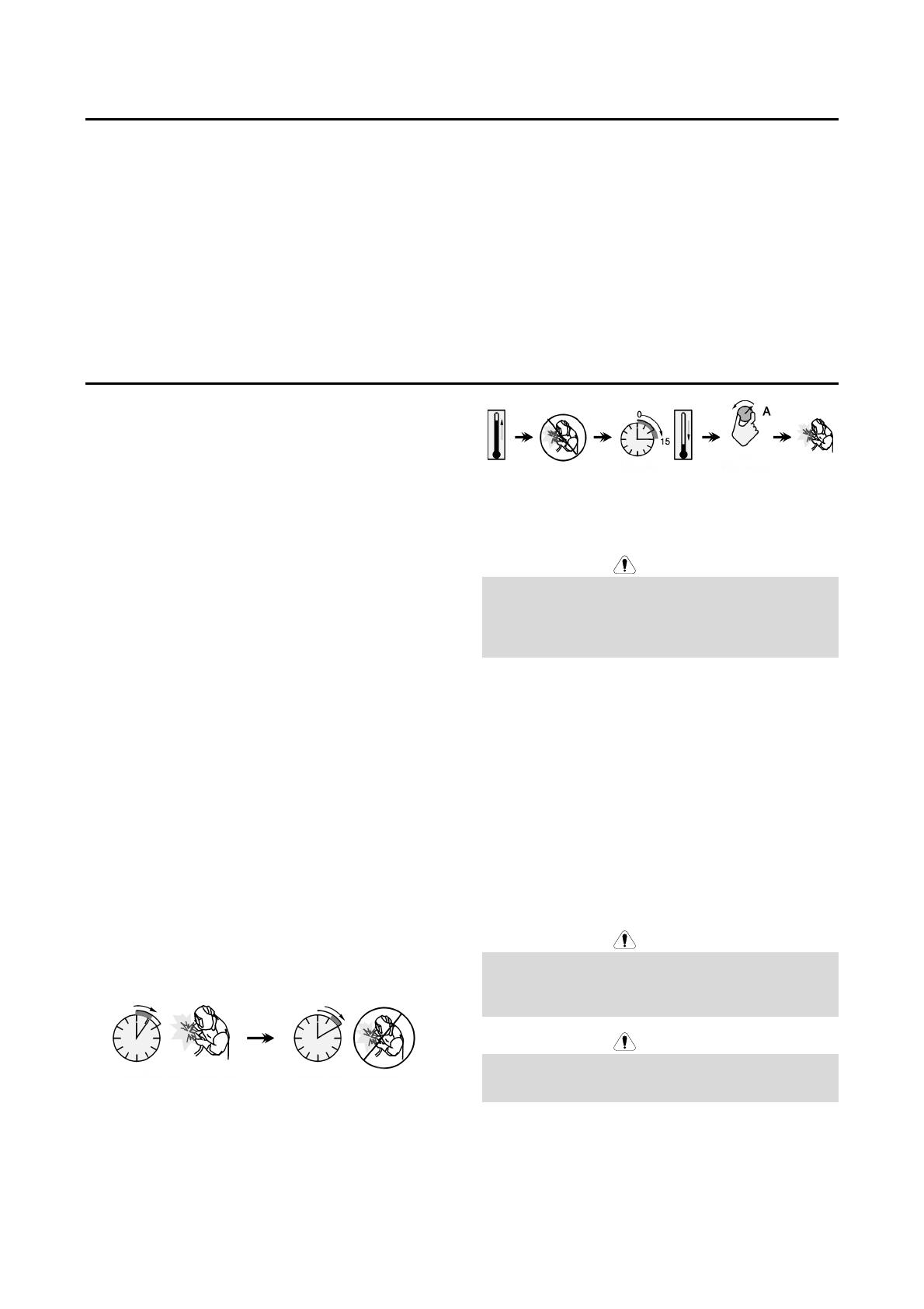
Duty cycle and Overheating
The duty cycle of a welding machine is the percentage of
time in a 10 minute cycle at which the welder can operate
the machine at rated welding current.
Example: 60% duty cycle
Welding for 6 minutes. Break for 4 minutes.
Excessive extension of the duty cycle will cause the
thermal protection circuit to activate.
Minutes or decrease
duty cycle
Input Supply Connection
WARNING
Only a qualified electrician can connect the welding
machine to the supply network. Installation the outlet plug
to power lead and connecting the welding machine had to
be made in accordance with the appropriate National
Electrical Code and local regulations.
Check the input voltage, phase, and frequency supplied to
this machine before turning it on. Verify the connection of
grounding wires from the machine to the input source.
SPEEDTEC® 400SP&500SP can only be connected to a
mating grounded receptacle.
Input voltages is 3x400V 50/60Hz. For more information
about input supply refer to the technical specification
section of this manual and to the rating plate of the
machine.
Make sure that the amount of mains power available from
the input supply is adequate for normal operation of the
machine. The type of protection and cable sizes are
indicated in the technical specification section of this
manual.
WARNING
The welding machine can be supplied from a power
generator of output power at least 30% larger than input
power of the welding machine.
See "Technical Specifications" chapter.
WARNING
When powering welder from a generator be sure to turn
off welding machine first, before generator is shut down, in
order to prevent damage to welding machine!
Refer to points [1], and [8] of the images below.
English 9 English
Output Connections
Refer to points [5], [6] and [7] of the Figures below.
Controls and Operational Features
1. Power Switch ON/OFF (I/O): Controls the input power.
Be sure the power source is properly connected to the
mains supply before turning power on ("I").
2. Status Light: A two color light that indicates
system errors. Normal operation is steady
green light. Error conditions are indicated, per
Table 1.
NOTE: The status light will flash green, and sometimes
red and green, for up to one minute when the machine is
first turned on. When the power source is powered it can
take as long as 60 seconds for the machine to be ready to
weld. This is a normal situation as the machine goes
through initialization.
Table 1.
LED Light
Condition
Meaning
Only machines which using
ArcLink® protocol for
communication
Steady Green
System OK. Power source is
operational, and is communicating
normally with all healthy peripheral
equipment.
Blinking Green
Occurs during power up or a system
reset, and indicates the power source
is mapping (identifying)
each component in the system.
Normal for first 1-10 seconds after
power is turned on, or if the system
configuration is changed during
operation.
Alternating Green
and Red
If the status lights are flashing any
combination of red and green, errors
are present in the power source.
Individual code digits are flashed in
red with a long pause between digits.
If more than one code is present, the
codes will be separated by green light.
Read the error code before the
machine is turned off.
If occurs, to clear the error try to turn
Off the machine, wait for a few
seconds, then turn ON again. If the
error remains, a maintenance is
required. Please contact the nearest
authorized technical service center or
Lincoln Electric and report the error
code read.
Steady Red
Indicate no communication between
the power source and device which
has been connected to this power
source.
3. Thermal Overload Indicator: It indicates
that the machine is overloaded or that the
cooling is not sufficient.
4. Gas Connector: For connection a gas hose from
interconnecting cable.
5. Negative Output Socket for the Welding
Circuit: Depending on the configuration of
power source, for connecting a work lead,
the electrode holder with lead or the source/wire
feeder welding cable.
6. Positive Output Socket for the Welding
Circuit: Depending on the configuration of
power source, for connecting a work lead,
the electrode holder with lead or the
source/wire feeder welding cable..
7. Control Receptacle: 5 pins receptacle for
wire feeder or remote controller
connection. To communication wire
feeder or remote controller with power
source is used ArcLink® protocol.
1
2
3
5
6
7
4
Figure 1.
English 10 English
8
11
10
12
14
13
9
15
Figure 2.
8. Power lead (5m without plug): Connect the supply
plug to the existing input cable that is rated for the
machine as indicated in this manual, and conforms to
all applicable standards. This connection shall be
performed by a qualified person only.
9. Fuse F3: Use the 12,5A/400V (6,3x32mm) slow-blow
fuse. See "Spare Parts" chapter.
10. Fuse F4: Use the 6,3A/400V (6,3x32mm) slow-blow
fuse. See "Spare Parts" chapter.
11. Fuse F1: Use the 2A/400V (6,3x32mm) slow-blow
fuse. See "Spare Parts" chapter.
12. Fuse F2: Use the 2A/400V (6,3x32mm) slow-blow
fuse. See "Spare Parts" chapter.
13. Ethernet Socket: Allows to connect the
power source directly to a computer or to
a network for software updates ,
diagnostics (Power Wave Manager) or production
monitoring (CheckPoint®).
14. Gas Heater Socket: Usup = 24VAC, Pmax = 80W.
15. Gas Connector: For connection a gas hose from
cylinder.
16. Cover bracket: To install the welding and control
sockets on the rear panel of the machine (see
"Accessories" chapter) to connect the wire feeder.
Welding Cables Connection
Insert the plug of the work lead into the socket [5]. The
other end of this lead connects to the work piece with the
work clamp.
Connect the wire feeder to the power source:
Insert the positive welding cable into the output socket
[6].
Insert the wire feeder control cable into the socket [7]
(see "Accessories" chapter, Source/wire feeder cable
K10198-PG-xM or K10199-PGW-xM).
Use the shortest possible cable lengths.
Water Cooler Connection
SPEEDTEC® 400SP&500SP work with the water cooler
COOLARC® 60 (see "Accessories" chapter).
WARNING
Read and understand the cool er manual before
connecting it to the power source.
Before connecting cooler, refer to the manual of
wire feeder.
The COOLARC® 60 is supplied by welding power source
using 10-PIN socket.
Input voltages is 400V, 50/60Hz. Connect the cooler in
accordance with the instructions supplied with
COOLARC® 60.
Figure 3.
English 11 English
Connection to the Ethernet network
SPEEDTEC® 400SP&500SP is equipped with an ethernet
communication interface (RJ45 socket).
Default power source settings are designated to Direct
Connection where PC IP address is set to range
169.254.0.
SPEEDTEC® default factory settings
DHCP off
IP Address 169.254.0.2
Subnet Mask 255.255.255.0
Default gateway 169.254.0.1
SPEEDTEC® with PC Connection
According to network infrastructure we can distinguish 2
different connection types:
1. Direct Connection
2. Local Area Network
a) with static IP addresses
b) with dynamic IP addresses (DHCP server, e.g.
Router)
Direct Connection
The simplest case where SPEEDTEC® is connected to
PC with one, common ethernet cable.
Use above network settings for your PC.
Please refer guide how to change TCP/IP settings (IP
address) in your PC operating system available in your
system help or internet.
WARNING
Sometimes 5 minutes delay is require after ethernet cable
was connected to establish the connection between
SPEEDTEC® and PC (especially when your PC was set
to Obtain an IP address automatically” from DHCP server
before).
English 12 English
2. Local Area Network
a) Static IP Addresses
When SPEEDTEC® is connected to the network which is
equipped with a Hub or Switch (no DHCP server) it is
required to set proper IP address from the actual
subnetwork range to SPEEDTEC® and PC.
Example:
Please refer guide how to change TCP/IP settings (IP
address) in your PC operating system available in your
system help or internet.
In order to change SPEEDTEC® IP address use Direct
Connection first (see chapter 1) to change SPEEDTEC®
configuration.
connect to SPEEDTEC® by Direct Connection
run Power Wave Manager software on your PC
(available on www.powerwavesoftware.com)
Step 1: choice “I do not know the IP address of the
welder
Step 2: click on row with SPEEDTEC® IP Address and
Model Name
Step 3: click on “Configure” button
Step 4: change IP address, Subnet mask, Default
gateway
Step 5: click “OK” button
Confirm new settings by clicking “Yes”. Machine will
be restarted.
Connect SPEEDTEC® to Network Switch back.
English 13 English
b) Dynamic IP Addresses (DHCP Server, e.g. Router)
When SPEEDTEC® is connected to the network which is
equipped with a DHCP server it is required to set proper
configuration of the SPEEDTEC® and PC.
Please refer guide how to change TCP/IP settings to
Obtain an IP address automatically in your PC operating
system available in your system help or internet.
In order to switch SPEEDTEC® to “Obtain an IP address
automatically” use Direct Connection first (see chapter a)
to change SPEEDTEC® configuration.
connect to SPEEDTEC® by Direct Connection
run Power Wave Manager software on your PC
(available on
www.powerwavesoftware.com)
Step 1: choice “I do not know the IP address of the
welder”
Step 2: click on row with SPEEDTEC® IP Address and
Model Name
Step 3: click on “Configure” button
Step 4: choice “Obtain an IP address automatically”
Step 5: click “OK” button
Confirm new settings by clicking “Yes”. Machine will
be restarted.
Connect SPEEDTEC® to Network Router.
Machine and Circuit Protection
Power Source is protected against overheating, overload
and accidental short-circuits.
If the machine is overheated, the thermal protection circuit
will decrease the output current to 0. The thermal
protection indicator [3] will turn on.
The Power Source is also electronically protected against
overload and accidental short-circuit. The overload and
short-circuit protection circuit automatically reduces the
output current to a safe value when it detects an overload.
English 14 English
Transport & Lifting
WARNING
Falling equipment can cause injury and
damage to unit.
Figure 4
During transportation and lifting with a crane, adhere to
the following rules:
Power source does not include the eye bolt which can
be used to transport or lifting the machine.
To lift use of suitable lifting equipment capacity.
To lifting and transport use a travers and minimum two
belts.
Lift only power source without gas cylinder, cooler and
wire feeder, or/and any other accessories.
Maintenance
WARNING
For any repair operations, modifications or maintenances,
it is recommended to contact the nearest Technical
Service Center or Lincoln Electric. Repairs and
modifications performed by unauthorized service or
personnel will cause, that the manufacturer’s warranty will
become null and void.
Any noticeable damage should be reported immediately
and repaired.
Routine maintenance (everyday)
Check condition of insulation and connections of the
work leads and insulation of power lead. If any
insulation damage exists replace the lead
immediately.
Remove the spatters from the welding gun nozzle.
Spatters could interfere with the shielding gas flow to
the arc.
Check the welding gun condition: replace it, if
necessary.
Check condition and operation of the cooling fan.
Keep clean its airflow slots.
Periodic maintenance (every 200 working hours but at
list once every year)
Perform the routine maintenance and, in addition:
Keep the machine clean. Using a dry (and low
pressure) airflow, remove the dust from the external
case and from the cabinet inside.
If it is required, clean and tighten all weld terminals.
The frequency of the maintenance operations may vary in
accordance with the working environment where the
machine is placed.
WARNING
Do not touch electrically live parts.
WARNING
Before the case of welding machine will be removed, the
welding machine had to be turned off and the power lead
had to be disconnected from mains socket.
WARNING
Mains supply network must be disconnected from the
machine before each maintenance and service. After
each repair, perform proper tests to ensure safety.
English 15 English
Customer Assistance Policy
The business of The Lincoln Electric Company is
manufacturing and selling high quality welding equipment,
consumables, and cutting equipment. Our challenge is to
meet the needs of our customers and to exceed their
expectations. On occasion, purchasers may ask Lincoln
Electric for advice or information about their use of our
products. We respond to our customers based on the best
information in our possession at that time. Lincoln Electric
is not in a position to warrant or guarantee such advice,
and assumes no liability, with respect to such information
or advice. We expressly disclaim any warranty of any
kind, including any warranty of fitness for any customer’s
particular purpose, with respect to such information or
advice. As a matter of practical consideration, we also
cannot assume any responsibility for updating or
correcting any such information or advice once it has
been given, nor does the provision of information or
advice create, expand or alter any warranty with respect
to the sale of our products
Lincoln Electric is a responsive manufacturer, but the
selection and use of specific products sold by Lincoln
Electric is solely within the control of, and remains the sole
responsibility of the customer. Many variables beyond the
control of Lincoln Electric affect the results obtained in
applying these types of fabrication methods and service
requirements.
Subject to Change – This information is accurate to the
best of our knowledge at the time of printing. Please refer
to www.lincolnelectric.com for any updated information.
English 16 English
WEEE
07/06
Do not dispose of electrical equipment together with normal waste!
In observance of European Directive 2012/19/EC on Waste Electrical and Electronic Equipment (WEEE)
and its implementation in accordance with national law, electrical equipment that has reached the end of its
life must be collected separately and returned to an environmentally compatible recycling facility. As the
owner of the equipment, you should get information on approved collection systems from our local
representative.
By applying this European Directive you will protect the environment and human health!
Spare Parts
12/05
Part List reading instructions
Do not use this part list for a machine if its code number is not listed. Contact the Lincoln Electric Service Department
for any code number not listed.
Use the illustration of assembly page and the table below to determine where the part is located for your particular
code machine.
Use only the parts marked "X" in the column under the heading number called for in the assembly page (# indicate a
change in this printing).
First, read the Part List reading instructions above, then refer to the "Spare Part" manual supplied with the machine, that
contains a picture-descriptive part number cross-reference.
REACh
11/19
Communication in accordance with Article 33.1 of Regulation (EC) No 1907/2006 – REACh.
Some parts inside this product contain:
Bisphenol A, BPA, EC 201-245-8, CAS 80-05-7
Cadmium, EC 231-152-8, CAS 7440-43-9
Lead, EC 231-100-4, CAS 7439-92-1
Phenol, 4-nonyl-, branched, EC 284-325-5, CAS 84852-15-3
in more than 0,1% w/w in homogeneous material. These substances are included in the “Candidate List of Substances of
Very High Concern for Authorisation” of REACh.
Your particular product may contain one or more of the listed substances.
Instructions for safe use:
use according to Manufacturer instructions, wash hands after use;
keep out of reach of children, do not put in mouth,
dispose in accordance with local regulations.
Authorized Service Shops Location
09/16
The purchaser must contact a Lincoln Authorized Service Facility (LASF) about any defect claimed under Lincoln's
warranty period.
Contact your local Lincoln Sales Representative for assistance in locating a LASF or go to www.lincolnelectric.com/en-
gb/Support/Locator.
Electrical Schematic
Refer to the "Spare Part" manual supplied with the machine.
English 17 English
Accessories Suggested
K14335-1 LF 52D
K14336-1 LF 56D
K14297-1 COOLARC® 60
W000010167 FREEZCOOL 9,6L
K14298-1 4-WEELS CART
K14337-1 OUTPUT CONNECTION KIT (400SP&500SP)
Welding cables
GRD-400A-70-5M GROUND CABLE 400A/70MM²; 5 m
GRD-400A-70-10M GROUND CABLE 400A/70MM²; 10 m
GRD-400A-70-15M GROUND CABLE 400A/70MM²; 15 m
GRD-600A-95-5M GROUND CABLE 600A/95MM²; 5 m
GRD-600A-95-10M GROUND CABLE 600A/95MM²; 10 m
E/H-400A-70-5M ELECTRODE HOLDER 400A/70MM² - 5 m
W000010136 FLAIR 600 GOUGING TORCH with airflow regulated on the torch
Intermediate hose package AIR
K14198-PG CABLE PACK 5PIN G 70MM2 1M
K14198-PG-3M CABLE PACK 5PIN G 70MM2 3M
K14198-PG-5M CABLE PACK 5PIN G 70MM2 5M
K14198-PG-10M CABLE PACK 5PIN G 70MM2 10M
K14198-PG-15M CABLE PACK 5PIN G 95MM2 15M
K14198-PG-20M CABLE PACK 5PIN G 95MM2 20M
K14198-PG-25M CABLE PACK 5PIN G 95MM2 25M
K14198-PG-30M CABLE PACK 5PIN G 95MM2 30M
Intermediate hose package WATER
K14199-PGW CABLE PACK 5PIN W 95MM2 1M
K14199-PGW-3M CABLE PACK 5PIN W 95MM2 3M
K14199-PGW-5M CABLE PACK 5PIN W 95MM2 5M
K14199-PGW-10M CABLE PACK 5PIN W 95MM2 10M
K14199-PGW-15M CABLE PACK 5PIN W 95MM2 15M
K14199-PGW-20M CABLE PACK 5PIN W 95MM2 20M
K14199-PGW-25M CABLE PACK 5PIN W 95MM2 25M
K14199-PGW-30M CABLE PACK 5PIN W 95MM2 30M
English 18 English
Connection configuration
SPEEDTEC 400SP K14258-1
SPEEDTEC 500SP K14259-1
LF 52D K14335-1
LF 56D K14336-1
COOLARC 60
K14297-1
K14198-PG
K14198-PG-XM
K14199-PGW
K14199-PGW-XM
  • Page 1 1
  • Page 2 2
  • Page 3 3
  • Page 4 4
  • Page 5 5
  • Page 6 6
  • Page 7 7
  • Page 8 8
  • Page 9 9
  • Page 10 10
  • Page 11 11
  • Page 12 12
  • Page 13 13
  • Page 14 14
  • Page 15 15
  • Page 16 16
  • Page 17 17
  • Page 18 18
  • Page 19 19
  • Page 20 20

Lincoln Electric SPEEDTEC 400SP and 500SP User manual

Category
Welding System
Type
User manual

Lincoln Electric SPEEDTEC 400SP and 500SP are professional welding machines designed for industrial use. They offer precise welding performance with a wide range of welding processes, including MIG/MAG, FCAW, SMAW, and GTAW. With their robust construction and advanced features, these machines are ideal for demanding welding applications in various industries.

Ask a question and I''ll find the answer in the document

Finding information in a document is now easier with AI