Topens DKC1000(S-Y) Sliding Gate Opener User manual

Category
Gate Opener
Type
User manual

Topens DKC1000(S-Y) Sliding Gate Opener is a reliable and powerful automatic gate opener designed to enhance security and convenience for your property. With its robust construction and advanced features, this opener is ideal for both residential and commercial applications. It ensures smooth and secure operation of your sliding gate, providing you with peace of mind and effortless access control.

Topens DKC1000(S-Y) Sliding Gate Opener is a reliable and powerful automatic gate opener designed to enhance security and convenience for your property. With its robust construction and advanced features, this opener is ideal for both residential and commercial applications. It ensures smooth and secure operation of your sliding gate, providing you with peace of mind and effortless access control.

Sliding Gate Opener
User’s Manual
Model:
TOPENS Website
www.topens.com
Email: suppor[email protected]om
VER 21b
DKC1000(S/Y)
Please read and follow all warnings, precautions and instructions before
installation and use.
Never connect the solar panel to the control board directly to charge the battery.
Periodic checks of the opener are required to ensure safe operation.
Save this manual.
C030415
CONTACT US:
Visit: www.topens.com
Please record the product model, your email address etc.
in the spaces provided below. Refer to this list when contacting TOPENS
for technical service or assistance with your automatic gate opener.
Where did you purchase? (Amazon.com; Amazon.ca: Amazon.co.uk, Amazon.de; Other, Please
Specify)
Order#
Product Model
Purchase Date
Full Name Phone# Email Address (VERY
IMPORTANT)
Street Address, Apartment /Unit, City, State /Province, Zip Code
Country/Region
Approximate Gate Weight
(pounds; kg: Other. Please
Specify)
Approximate Gate Length
(feet; meter; Other. Please
Specify)
Did you purchase any
accessories? (Please list
below)
Issue Details
Email Us: support@topens.com
Call: +1 (888) 750 9899 (Toll Free USA & Canada)
Table of Contents
Check Your Gate before Installation ................................................................................................................ 1
General Safety ................................................................................................................................................. 1
Preparation for Installation ............................................................................................................................... 2
Parts List ........................................................................................................................................................... 4
Extra Parts ........................................................................................................................................................ 4
Accessories Parts (Included in some models, refers to the actual package) .................................................. 5
Optional Accessories Parts List (Available at TOPENS Store) ........................................................................ 5
Replacement Parts ........................................................................................................................................... 5
Technical Specifications & Features ................................................................................................................ 6
Installation Overview ........................................................................................................................................ 7
Installation of the Opener ................................................................................................................................. 7
Manual Operation ............................................................................................................................................. 8
Installation of chain and chain brackets ........................................................................................................... 8
Installation of the Magnets ............................................................................................................................... 9
Connection of the Power Supply .................................................................................................................... 10
Connecting of the Control Board .................................................................................................................... 13
Setting of the Control Board ........................................................................................................................... 15
Test the Reversing Sensitivity ........................................................................................................................ 17
How to Program or Erase the Remote ........................................................................................................... 17
How to Use the Remote to Operate Your Gate Opener ................................................................................ 18
Wireless Keypad Programming...................................................................................................................... 18
Troubleshooting .............................................................................................................................................. 19
Maintenance
................................................................................................................................................... 20
European Representative:
....................................................................................................
错误
!
未定义书签。
Feedback & Review ....................................................................................................................................... 23
1
Thank you for purchasing our sliding gate opener. We are sure that the products will be greatly satisfying as
soon as you start to use it.
The product is supplied with a users manual which encloses installation and safety precautions. These
should be read carefully before installation and operation as they provide important information about safety,
installation, operation and maintenance. This product complies with the recognized technical standards and
safety regulations.
Check Your Gate before Installation
General Safety
WARNING! An incorrect installation or improper use of the product can cause damage to persons,
animals or properties.
• Scrap packing materials (plastic, cardboard, polystyrene etc.) according to the provisions set out by current
standards. Keep nylon or polystyrene bags out of children’s reach.
• This product was exclusively designed and manufactured for the use specified in the present documentation.
Any other use not specified in this documentation could damage the product and be dangerous.
• The factory declines all responsibility for any consequences resulting from improper use of the product, or
use which is different from that expected and specified in the present documentation.
• Do not install the product in explosive atmosphere.
• The factory declines all responsibility for any consequences resulting from failure to observe Good Technical
Practice when constructing closing structures (door, gates etc.), as well as from any deformation which might
occur during use.
• Disconnect the electrical power supply before carrying out any work on the installation. Also disconnect any
buffer batteries, if fitted.
• Fit an omnipolar or magnetothermal switch on the mains power supply, having a contact opening distance
equal to or greater than 3,5 mm.
Make sure a residual current circuit breaker with a 30mA threshold is fitted before the power supply mains.
• Check that earthing is carried out correctly: connect all metal parts for closure (doors, gates etc.) and all
system components provided with an earth terminal.
• Fit all the safety devices (photocells, electric edges etc.) which are needed to protect the area from any
danger caused by squashing, conveying and shearing.
2
• Position at least one visible indication device (Alarm lamp), and fix a Warning sign to the structure.
• The factory declines all responsibility with respect to the automation safety and correct operation when
other supplier’s components are used.
• Only use original parts for any maintenance or repair operation.
• Do not modify the automation components, unless explicitly authorized by the factory.
• Instruct the product user about the control systems provided and the manual opening operation in case of
emergency.
• Do not allow persons or children to remain in the automation operation area.
• Keep radio control or other control devices out of children’s reach, in order to avoid unintentional automation
activation.
• The user must avoid any attempt to carry out work or repair on the automation system, and always request
the assistance of qualified personnel.
Anything which is not expressly provided for in the present instructions is not allowed.
Before installing the gate opener, check that all moving part as well as the sliding gate is in good mechanical
condition, correctly balanced and opens and closes properly.
Save these instructions for future use.
Preparation for Installation
Before proceeding to your opener installation, check if your gate structure is in accordance with the current
standards, especially as follows:
The gate sliding track is linear and horizontal. The wheels are suitable for use. The gate should be mounted
and moved freely. Check that the structure is sufficiently strong and rigid, and that its dimensions and weights
conform to those listed in the specifications table of this document. Make sure that the gate is plumb and
level. The fence posts must be mounted in concrete. The gate does not bind or drag on the ground.
• The gate manual operation can be carried out smoothly along its entire run, and there is no excessive side
slipping.
• The opening and closing gate stops are positioned.
WARNING: Remember that control devices are intended to facilitate gate operation, but can not
solve problems due to any defects or deficiency resulting from failure to carry out correct installation or
maintenance. Take the product out of its packing and inspect it for damage. Should it be damaged, contact
your dealer. Remember to dispose of its components (cardboard, polystyrene, nylon, etc.) according to the
current prescriptions.
Refer to the following Figures for gate installation.
3
In sake of safety, a positive stop must be mounted on the two end of ground track.
4
Parts List
Extra Parts
5
Accessories Parts (Included in some models, refers to the actual package)
Optional Accessories Parts List (Available at TOPENS Store)
M12 Remote Control ERM12 External
Receiver
TC186-R WiFi
Smartphone Remote
Control with Camera
TC186 WiFi Smartphone
Remote Control with
Camera
TKP3 Wireless Keypad TC175P Wired Keypad TEW3 Vehicle Sensor
Exit Wand
HLR01 HomeLink Remote
Control Kit
TC173 Wireless Push
Button
TC147 Wired Push
TRF3 Reflection
Photocell Sensor
TC102 Photo Eye Beam
Sensor
JD24VY 24V Warning
Light
TSP30W 30W Solar
TCS3 Solar Charge
Controller
LT08B 20 Feet Roller
Chain
Replacement Parts
DKPYMJ2A Control
Board
PYMJ-CKG Limit Switch
WARNING: Changes or modifications not expressly specified by this user manual, TOPENS could void
the warranty of this equipment.
6
Technical Specifications & Features
Specifications
Model: DKC1000(S/Y)
Power supply:
110V~120V/60Hz or 220~240V/50Hz
Motor voltage: 24VDC
Absorbed power:
350W
Gate moving speed: 20 cm/s (8 in/s)
Max gate weight: 800kg (1800lbs)
Environmental conditions: -20~ + 50 (-4°F to 122°F)
Protection class: IP44
Features:
·
Soft start and soft stop.
·
Midway mode.
·
Quick selection for the gate open/close direction.
·
Reliable rolling code technology for remote
control.
·
Emergency release key in case of power failure.
·
Stop in case of obstruction during gate opening.
·
Reverse in case of obstruction during gate
closing.
·
Built in adjustable auto-close (none, 30, 60, 90
seconds).
·
Built in max. Motor Running Time (MRT) for
multiple safety protection (90 seconds)
·
Reliable electromagnetism limit for easy
adjustment.
·
Can be equipped with a wide range accessories.
·
Easy to install, and minimum maintenance
requirement.
·
Get the desired chain tension by adjusting the chain
bolts
7
Installation Overview
Installation of the Opener
Caution:
*Be sure that the opener is installed in a level and
paralleled position and is properly secured.
Improper installation could result in property
damage, severe injury, and/or death.* Before starting
installation, ensure that there is no point of friction
during the entire movement of the gate and there is
no danger of derailment.
* Ensure that the Warning Signs are present.
Necessary Tools: The following tools may be necessary
to install the Gate opener. You will need screwdrivers, an
electric drill, wire cutters and a wire stripper, a socket set,
and possibly access to a welder.
When install the opener, you should build a concrete pad
to support the base plate of opener in order to maintain
proper stability.
The installation proceeds are as follows:
1.Dig a hole for a concrete pad which should be
approximately 60 x 32 x 35cm (24x 13x 14). It may
protrude 10 cm (4”) above ground and 25 cm (10”) in
depth underground. Increase the pad height if necessary
to protect the system from flooding, heavy snow etc.
2. Prepare one or more conduits for the electrical cables before pour concrete. Remember that cable conduits
have to pass through the hole in the base plate.
3. Pour concrete and before it starts to harden, check that it is parallel to the gate leaf and perfectly level.
4. The four anchor bolts must be set into the concrete when it is poured, make sure the position of anchor
8
bolts was placed according to the position of mounting holes on the base plate before concrete become
harden.
5. Mount the base plate to the concrete Pad. It's only temporary installation. Further adjustment will be
required when install the chain.
6. Mount the chain box to the base plate by using screws and washers, dont make the four screws too
tight.
Manual Operation
The opener should be put in the manual (emergency release) position before fitting the chain, installing the
opener and limit switch. The process is as follows:
1) Take of the rubber stopple.
2) Insert the Release Keyprovidedand turn it in counter-clockwise 180° to disengage the clutch
between the gear shaft and power output. Now the opener is in the manual operation.
Installation of chain and chain brackets
1. Chain Brackets
1). Please refer to below chain brackets figure,
which shows “U” bolt, “L” bracket and chain bolt.
Use the “U” bolts (square or round) to attach the
chain brackets to gate frame.
2). If Both the square bolts and round bolts are not
fit for the gate frame, use the appropriate bolts to
attach the chain brackets to gate frame.
2. How to install the chain
1). Place the chain around the top of the idler
wheels and under the drive sprocket in chain box.
2). Connect a chain bolt to one end of chain from
chain box by using master link. Then insert the
chain bolt to the L bracket and fix them each other by washers and nuts temporarily. (Nuts will be further
adjusted for a proper chain tension later)
3). Connect second chain bolt with another end of chain from chain box, then attach bolt to the L bracket on
opposite end of gate using the washers and nuts.
4). Make sure that the chain is line up exactly with the position where the chain on the chain idler wheel.
5). Set appropriated chain tension by adjusting two chain bolts of the both end.
Cut the unwanted length of chain if necessary.
6). Fix the base plate by tightening the washers and nuts.
9
7). Insert the opener shaft into the drive sprocket of chain box.
Mount the opener by tightening the bolts and washers.
8). Fix the chain box by tightening the four lax screws.
* Thoroughly fasten the four nuts as well as spring washers
onto anchor bolts tightly, enabling the opener is firmly secured on the concrete pad during the whole
gate travel.
3. Check position of opener and chain brackets
1). The chain brackets must be mounted to the same height as the chain on the idler wheels.
2). The opener must be parallel to the gate.
3). Make sure there is 1distance at least between the chain box and the gate after you position the base
plate.
Installation of the Magnets
Before install limit switch, make sure the gate opener is put in manual operation. (the clutch connected with
gear shaft is disengaged) and the mains power supply is disconnected.
Position the two Magnet Components approximately on the gate and move the gate by hand to fix them in
place.
10
Fit magnets bracket
Push the gate fully closed by hand. Locate and install the magnet bracket so that the opener will stop at the
desired close position when the close limit switch approaches it.
Push the gate fully open by hand. Locate and install the magnet bracket so that the opener will stop at the
desired open position when the open limit switch approaches it.
The magnet component with N pole outside must be installed at left side and the magnet component
with S pole outside must be installed at right side from the view inside of property.
Ensure magnet center to align with the marked line above !
The magnets should be 20~30mm (0.8-1.2”) away from the Limit Switch Box. If it is too near or too far, the
switches will fail to work. Adjust the position of the magnets until the positions of the opening and closing
meet the requirement.
Connection of the Power Supply
WARNING: NEVER connect the gate opener to the power outlet before all the installations have
been done.
NOTE:
1. If batteries are chosen as the power source, Marine or Automotive Type Battery is required. The
batteries should be waterproof type, or be placed in water proof circumstance.
2. 2 PCS 12VDC batteries can be connected in series to function as 24VDC. The following diagram
shows on how to connect 2 PCS batteries in series.
3. Please note that the wire connection of the power supply system is very important. Incorrect wire
connection will damage the control board.
Warning: Improper magnets installation may cause the gate crash into end barrier,
which is very dangerous !
11
Power Mode 1. Only use the AC electricity as the power
source
The power supply cord should be at least 3×0.75mm2 (3C×18AWG). Connect the live
wire, neutral wire and earth wire to the “L”, “N” and “PE” terminals respectively.
NOTE: The power supply cord is not included in the package.
Power Mode 2. By AC electricity and back-up batteries, only use the AC
electricity to charge the batteries
If the AC electricity failure happens rarely (less than 8
hours per day), then you can use minimum 5Ah
2*12VDC batteries as back-up power source in case of
AC power failure. In this situation, you can connect the
AC electricity following the “Power Mode 1” and the
batteries to the BAT terminal of the control board
directly as the below wiring diagram.
Power Mode 3. Only use the batteries as the power source, only use the
solar panel to charge the batteries
If the AC electricity is not available, then you can choose the batteries as the power source and use the solar
panel to charge the batteries. The capacity of the batteries should be at least 12Ah and the power of the solar
panel should be at least 30W in this situation. The gate opener can run for 10 cycles per day without
connecting any other accessories except pushbutton & warning light if the local average sunshine time is
more than 6 hours per day. The power of the solar panel and the capacity of the batteries should be enlarged
if the local average sunshine time is less than 6 hours per day or using one of the accessories (photocell,
external receiver, exit wand and keypad). Please provide us with more details of the local sunshine condition
and accessories needs which we can calculate the configuration of the solar panel and the batteries. Please
connect the batteries & the solar panels & solar controller refer to the following wiring diagram.
12
Power Mode 4. By AC electricity and back-up batteries, use the AC
electricity and the solar panel to charge the batteries at the same time
If the AC electricity failure happens frequently and lasts for a long time (maybe 4-5 days one time), then you
can charge the batteries with the AC electricity and the solar panel at the same time. The capacity of the
batteries should be at least 7Ah and the power of the solar panel should be at least 20W in this situation. You
can connect the AC electricity following the “Power Mode 1” and the batteries & the solar panels & solar
controller refer to the following wiring diagram.
13
Connecting of the Control Board
1. Motor
The YELLOW wire of the motor should be connected into the “1” terminal.
The RED wire of the motor should be connected into the “2” terminal.
2. Limit Switches
The YELLOW wire of the limit switches should be connected into the “3” terminal.
The BLACK wire of the limit switches should be connected into the “4” terminal.
The RED wire of the limit switches should be connected into the “5” terminal.
3. Warning Light (Included in some models, refers to the actual package)
The WHITE wire of the warning light should be connected into the “6” terminal.
The RED wire of the warning light should be connected into the “7” terminal.
4. Photocell Beam System (PBS) (Included in some models, refers to the actual package)
Use a 2-core cable to connect the “- ~” terminal of the photocell’s emitter to the “19” terminal, the + ~
terminal to the 18 terminal. Also the “- ~” and + ~ terminals of the photocell’s receiver should be
connected to the “19” and 18 terminals in parallel.
Use another 2-core cable to connect the NC terminal of the receiver to the 13terminal, the COM
terminal to the 12terminal.
5. Push Button (optional)
The push button should be wired to the “16 and “17” terminals. No matter the polarity. The gate operator
works alternately by pressing the button (open-stop-close-stop-open).
14
6. Exit Wand (optional)
The BLACK wire of the exit wand should be connected into the “14terminal.
The BLUE wire of the exit wand should be connected into the “15” terminal.
The RED wire of the exit wand should be connected into the “18” terminal.
The GREEN wire of the exit wand should be connected into the “19” terminal.
The sensitivity adjustment board should be wired to the GREEN wire and the YELLOW wire of the wand. No
matter the polarity.
7. Battery (ONLY included in Y Series)
15
The “24V+” of the battery should be wired to the BAT+ (11) terminal, “24V-” should be wired to “-BAT (10)
terminal. If the battery has been used with solar panel, please connect the batteries and the solar panel
&solar controller following the chapter of Connection of the Power Supply”.
8. External Receiver (optional)
The BROWN wire of the external receiver should be connected into the “16” terminal.
The BLACK wire of the external receiver should be connected into the “17” terminal.
The RED wire of the external receiver should be connected into the “18” terminal.
9. Wired Keypad (24VDC) (optional)
The RED wire of the wired keypad should be connected into the “18 terminal.
The BLACK wire of the wired keypad should be connected into the “17” terminal.
The BLUE wire of the wired keypad should be connected into the “16” terminal.
The PURPLE wire of the wired keypad should be connected into the “17” terminal.
NOTE: Using of the photocell, exit wand, keypad and external receiver would cause the battery
exhausted quickly. Big capacity of batteries and big power of solar panel is required if you want to
use any one of them (If the batteries and solar panel is used as main power supply).
Setting of the Control Board
WARNING: Ensure the gate opener is Power Off when you make any adjustment of the gate
opener. Keep away from the path of the gate during you set the gate opener system in case of the
unexpected gate moving. Carefully adjust the DIP switches to avoid the risk of machine damage and
injury or death. Always ask the help of professional technician /electrician if you have any question.
1. DIP Switches
The DIP switches are used to set the running time of the
motor in Midway mode, fine adjust the soft stop period
of the motor, auto close time of the gate opener and
fast change the open/close direction which is
determined by the position of the gate opener installed.
DIP Switch #1–#2: Running time of the motor in Midway
Mode
DIP Switch #1: ON2 Seconds OFF – 0
DIP Switch #2: ON4 Seconds OFF – 0
NOTE: The midway mode function would be disabled if both DIP switches are turned off. Factory
default setting is disabled. The midway mode could be activated by pressing button B of the remote
control when the gate is in the full closed position.
E.g. Running time of the opener in midway mode is 2+4=6 seconds.
16
DIP Switch #3–#5: Fine adjust the soft stop period of the motor
DIP Switch #3: ON1 Second OFF – 0
DIP Switch #4: ON2 Seconds OFF – 0
DIP Switch #5: ON – 3 Seconds OFF – 0
NOTE: Every time you restart the gate opener after power off, you should use the access control
device (such as remote, push button and etc.) to operate the gate opener to run for a complete
opening cycle and a complete closing cycle to get the full opening time and the full closing time. You
would achieve the soft stop in your next opening/closing cycle. Factory default soft stop time is 3
Second. You can turn the DIP switches on/off to fine adjust the soft stop time to meet your actual
needs.
DIP Switch #6–#7: Auto close time of the gate opener
DIP Switch #6: ON30 Seconds OFF – 0
DIP Switch #7: ON60 Seconds OFF – 0
NOTE: The auto close function would be disabled if both DIP switches are turned to off (factory
default setting).
Important Note: When the auto close function is enabled, the photocell sensor is highly
recommended to be installed with the gate opener for safety.
DIP Switch #8: Left/Right open
2. Potentiometers
Potentiometer A is used to adjust the close stall force the gate operator. Turn clockwise to increase the stall
force, and turn it counter-clockwise to decrease the stall force.
Potentiometer B is used to adjust the open stall force the gate operator. Turn clockwise to increase the stall
force, and turn it counter-clockwise to decrease the stall force.
WARNING: Photocell is highly recommended to be installed with the gate opener as entrapment
protection for safety when you set stall force to maximum.
E.g. The soft stop period of the motor is 1+2=3 seconds.
E.g. Auto close time of the gate opener is 30+60=90 seconds.
17
Test the Reversing Sensitivity
For the sake of safety, it is very important to test the reversing sensitivity as soon as the control board set is
finished.
The reversing sensitivity adjustment is inverse correlation with stall force adjustment in potentiometer A and
B. In other word, the stall force level is higher; the reversing sensitivity level is lower.
Put an immobile object along the gate path, and then operate the gate to strike it during the close cycles. The
gate must reverse as soon as object is struck with it. If the gate doesn’t reverse, please increase the reversing
sensitivity by turning the potentiometer in counter-clockwise direction. (Turning the stall force potentiometer
toward to MIN position to increase the reversing sensitivity)
Note 1: If the sensitivity setting is too higher, the gate will stop or reverses very easy by itself while
there is little obstruction or resistance such as strong wind or heavy snow sometimes.
Note 2: Always check the gate reversing function every each time of control board set or restart after
power off.
How to Program or Erase the Remote
The remote MUST be programed to the opener BEFORE OPERATING. Please follow the steps to
program the remote.
Activate the opener only when gate is in full view, free of obstruction and properly adjusted. No
one should enter or leave gate area while gate is in motion. DO NOT ALLOW CHILDREN to operate
push button or remote. DO NOT ALLOW CHILDREN TO PLAY NEAR THE GATE.
If you purchase additional remote controls, the gate opener must be programmed to accept the
new remote code.
If you lose one of any remote control, please erase and reprogram all other remote controls to
have a new code for safety.
Program the remote
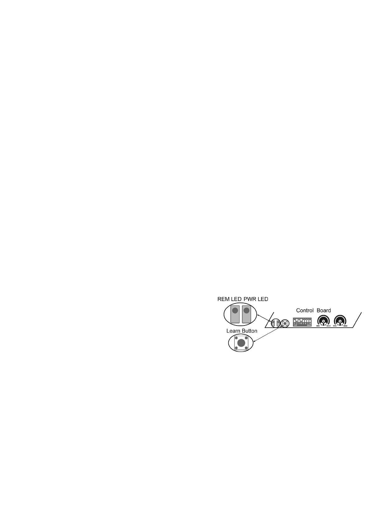
Press and release the learn button, the REM LED light will be
on, then press the key in the remote two times in 2 seconds,
between the two times HOLD ON FOR A MOMENT, the REM
LED light will flash for 4 seconds. Now the remote has been
programmed successfully.
Erase all the remote codes
Press and hold the learn button until the REM LED light is off. Now all remote codes have been erased.
NOTE: Max. 8 remotes can be programmed for the opener. An External Receiver (optional) allows up to
250pcs remotes to be programmed for the opener. TOPENS ERM12 Universal External Receiver is
available at TOPENS Store.
TOPENS ERM12 Universal External Receiver is also compatible with other brand swing gate opener,
sliding gate opener and garage door opener.
  • Page 1 1
  • Page 2 2
  • Page 3 3
  • Page 4 4
  • Page 5 5
  • Page 6 6
  • Page 7 7
  • Page 8 8
  • Page 9 9
  • Page 10 10
  • Page 11 11
  • Page 12 12
  • Page 13 13
  • Page 14 14
  • Page 15 15
  • Page 16 16
  • Page 17 17
  • Page 18 18
  • Page 19 19
  • Page 20 20
  • Page 21 21
  • Page 22 22
  • Page 23 23
  • Page 24 24
  • Page 25 25
  • Page 26 26

Topens DKC1000(S-Y) Sliding Gate Opener User manual

Category
Gate Opener
Type
User manual

Topens DKC1000(S-Y) Sliding Gate Opener is a reliable and powerful automatic gate opener designed to enhance security and convenience for your property. With its robust construction and advanced features, this opener is ideal for both residential and commercial applications. It ensures smooth and secure operation of your sliding gate, providing you with peace of mind and effortless access control.

Ask a question and I''ll find the answer in the document

Finding information in a document is now easier with AI