Page is loading ...

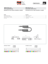
KT425-ZL
50.1138-*
(1+2+3+7)
LS425-ZL
49.2030
(4)
LS425-ZL/M3
49.2029
(5)
FLEXI-E 2,5
60.7012-*
SILI-E 2,5
61.7556-*
green-yellow
black
red
blue
yellow
green
violet
brown
grey
white
transparent
2021 22 23 24 25 26 27 28 29 33
* Available colours: 21-25 + 29
MA130 (de_en)
Montageanleitung
MA130 (de_en)
Assembly instructions
Axiale Ø 4mm-Stecker SLS425-ZL, SLS425-ZL/M3 In-line Ø 4mm plugs SLS425-ZL, SLS425-ZL/M3
Inhalt
Sicherheitshinweise....................................................................2
Notwendiges Werkzeug ............................................................3
Vorbereitung der Leitung ...........................................................3
Löten .........................................................................................3
Schrauben .................................................................................3
Montage ....................................................................................4
Content
Safety Instructions ......................................................................2
Tools required ............................................................................3
Preparation of the cable ............................................................3
Soldering ...................................................................................3
Screwing ...................................................................................3
Assembly ................................................................................... 4
* Lieferbare Farben: 21-25 + 29
grün-gelb
schwarz
rot
blau
gelb
grün
violett
braun
grau
weiss
transparent
2021 22 23 24 25 26 27 28 29 33

Erklärung der Symbole Explanation of the symbols
Warnung vor gefährlicher elektrischer Spannung Warning of dangerous voltages
Warnung vor einer Gefahrenstelle Warning of a hazard area
Nützlicher Hinweis oder Tipp Useful hint or tip
Sicherheitshinweise Safety instructions
Die Montage und Installation der Produkte darf ausschliess-
lich durch qualifi ziertes und erfahrenes Fachpersonal unter
Berücksichtigung aller anwendbaren gesetzlichen Sicher-
heitsbestimmungen und Regelungen erfolgen.
Multi-Contact (MC) lehnt jegliche Haftung infolge Nichteinhal-
tung dieser Warnhinweise ab.
The products may be assembled and installed exclusively by
suitably qualifi ed and trained specialists duly observing all ap-
plicable safety regulations.
Multi-Contact (MC) does not accept any liability in the event of
failure to observe these warnings.
Benutzen Sie nur die von MC angegebenen Einzelteile und
Werkzeuge. Weichen Sie nicht von den hier beschriebenen
Vorgängen zur Vorbereitung und Montage ab, da sonst bei der
Selbstkonfektionierung weder die Sicherheit noch die Einhal-
tung der technischen Daten gewährleistet ist. Ändern Sie das
Produkt nicht in irgend einer Weise ab.
Use only the components and tools specifi ed by MC. In case
of self-assembly, do not deviate from the preparation and as-
sembly instructions as stated herein, otherwise MC cannot
give any guarantee as to safety or conformity with the techni-
cal data. Do not modify the product in any way.
Der Schutz vor einem elektrischen Schlag müssen
bei Installation und Montage/Demontage immer
alle Bauteile spannungsfrei sein.
For protection against electric shock, parts must
be isolated from the power supply while being as-
sembled or disassembled.
Die Steckverbindungen dürfen nicht unter Last
getrennt werden. Das Stecken und Trennen unter
Spannung ist zulässig.
The plug connections must not be disconnected
under load. Plugging and unplugging when live is
permitted.
Vor jedem Gebrauch ist durch Besichtigen (im be-
sonderen die Isolation) zu prüfen, ob keine äusseren
Mängel vorhanden sind. Wenn Zweifel bezüglich der
Sicherheit bestehen, muss ein Fachmann hinzuge-
zogen werden oder der Steckverbinder muss ausge-
tauscht werden.
Each time the connector is used, it should previously
be inspected for external defects (particularly in the
insulation). If there are any doubts as to its safety, a
specialist must be consulted or the connector must
be replaced.
Weitere technische Daten entnehmen Sie bitte dem
Produktkatalog.
For further technical data please see the product
catalogue.

3
1
4
2
5
7
6
8
Notwendiges Werkzeug Tools required
(ill. 1)
Abisolierzange „Stripax“
Bestell-Nr. 25.0015
(ill. 1)
Cable stripper “Stripax”
Order No. 25.0015
(ill. 2)
- Lötkolben 60 W
- Lötdraht
z.B. bleifreies Lot
Ø 1,5#58/405
(SN95.8Ag3.5Cu.7)
ANSI/J-STD-004
Bezugsquelle:
www.kester-online.de
(ill. 2)
- Soldering iron 60 W
- Solder
e.g. lead free solder
Ø 1,5#58/405
(SN95.8Ag3.5Cu.7)
ANSI/J-STD-004
Source of supply:
www.kester-online.de
(ill. 3)
Gebogene Elektronik Spitzzange.
(ill. 3)
Angled-nose electrical pliers
(ill. 4)
Sechskantschlüssel für Stiftschrauben
Grösse 1,5mm STS1,5
Bestell-Nr. 25.0035.
(ill. 4)
Hexagonal wrench 1,5mm STS1,5
Order No 25.0035
Vorbereitung der Leitung Preparation of the cable
(ill. 5)
Leitung 6 auf die gewünschte Nenn-
länge abschneiden und das Isolierteil
7 aufziehen.
(ill. 5)
Cut the cable 6 to the desired nominal
length and slide the insulator 7 onto
the cable.
(ill. 6)
Leitung mittels Abisolierzange auf
8mm abisolieren.
(ill. 6)
Strip the cable to length 8mm with
cable stripper.
Löten Soldering
(ill. 7)
Leitung 6 in Stecker 4 löten.
(ill. 7)
Solder cable 6 in plug 4.
Hinweis:
Ein Block mit einer Bohrung von
Ø 4,2mm hält den Stecker 4 beim
Löten fest.
Note:
For soldering purposes a block
with a drilled hole Ø 4,2mm should
be used to hold the plug 4 in po-
sition
Schrauben Screwing
(ill. 8)
Passende Aderendhülse (siehe Zeich-
nung) auf Leitung 6 pressen und die
Leitung in Stecker 5 einführen und
festschrauben.
(ill. 8)
Crimp a wire end ferrule (see drawing)
onto cable 6 and feed the cable into
plug 5 and screw tightly.
wire end ferrule
Aderendhülse

Advanced Contact Technology
9
10
11
12
13
© by Multi-Contact AG, Switzerland – MA130 – 03.2013, Index f, Global Communications – Änderungen vorbehalten / Subject to alterations
Montage Assembly
(ill. 9)
Stecker 4 bzw. 5 in Isolationsteil 7 bis
zum Anschlag einführen und dabei die
geraden Flächen des Steckers mit den
geraden Flächen des Isolationsteils
ausrichten (Schnitt A-A)
(ill. 9)
Feed plug 4 resp. 5 into insulator 7
aligning the fl ats of the plug with
those in the insulator (Section A-A).
(ill. 10)
Feder 3, Schutzhülse 2 und Isolations-
teil 1 in dieser Reihenfolge von vorne
auf den Stecker (4 bzw. 5) aufstecken.
Die Nocken des Isolationsteils 1 müs-
sen dabei mit den Aussparungen des
Isolationsteils 7 ausgerichtet werden
(X).
(ill. 10)
In turn, mount spring 3, safety shroud
2 and insulator 1 onto the plug (4
resp. 5). The snap-in locator and open-
ing (X) of two insulators 1 and 7 must
be in line.
(ill. 11)
Vollständige Einrastung auf beiden
Seiten optisch kontrollieren.
(ill. 11)
Visually check the snap-in parts on
both sides for correct assembly!
(ill. 12)
Zugentlastungs-Stöpsel mit der Elek-
tronik Spitzzange bis zum Einrasten
eindrücken.
(ill. 12)
Press-in the cable strain re-lief stopper
with the angled-nose pliers.
(ill. 13)
Vollständige Einrastung optisch kont-
rollieren!
(ill. 13)
Visually check the snap-in parts for
correct assembly!
/