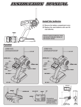
Traxxas TRX-4 Blazer User manual

Category
Remote controlled toys
Type
User manual
MODEL 82076-4
0
0
owner
s manual
2
TRX-4
3 BEFORE YOU
PROCEED
4 SAFETY
PRECAUTIONS
7 TOOLS, SUPPLIES,
AND REQUIRED
EQUIPMENT
8
ANATOMY OF
THE TRX-4 BLAZER
10
QUICK START:
GETTING UP
TO SPEED
11
TRAXXAS TQ
i
RADIO SYSTEM
18 ADJUSTING THE
ELECTRONIC SPEED
CONTROL
21
DRIVING YOUR MODEL
25 TUNING
ADJUSTMENTS
30 MAINTAINING
YOUR MODEL
31
TQ
i
ADVANCED
TUNING GUIDE
introduction
Thank you for purchasing the Traxxas TRX-4 with the 1979
Chevrolet Blazer Body Kit. This officially licensed model gets
the full Traxxas treatment with unsurpassed realism, including
molded chrome grill, side mirrors, door handles, and bumpers. The
design of the TRX-4 instantly obsoletes the status quo with greatly
expanded features and versatility. The TRX-4 features the powerful
Titan
®
21T 550 motor, waterproof electronics, and a smooth XL-5
HV 3s LiPo-capable electronic speed control. The game-changing
portal axles provide greater ground clearance while the rigid steel
frame eliminates chassis flex and allows you to navigate tough
terrain. The Canyon Trail 1.9 tires feature tuned foam inserts to
deliver superior bite on rocky surfaces. In other words, we built it
the Traxxas way -- rugged, powerful, and ready to handle the rigors
of remote locations and all-day driving fun!
This manual contains the instructions you will need to operate and
maintain your model so that you can enjoy it for years to come.
We want you to feel confident that you own one of the best-
performing models in the market and that it is backed by a team
of professionals who aim to provide the highest level of factory
support possible. Traxxas models are about experiencing total
performance and satisfaction, not just with your model, but also
with the company that stands behind it.
We know you’re excited about getting your new model on the trail,
but it’s very important that you take some time to read through the
Owner’s Manual. This manual contains all the necessary setup and
operating procedures that allow you to unlock the performance
and potential that Traxxas engineers designed into your model.
Even if you are an experienced R/C enthusiast, it’s important to
read and follow the procedures in this manual.
Thank you again for going with Traxxas. We work hard every day
to assure you the highest level of customer satisfaction possible.
We truly want you to enjoy your new model!
Traxxas Support
Traxxas support is with you every step of the
way. Refer to the next page to find out how to
contact us and what your support options are.
Quick Start
This manual is designed with a Quick
Start path that outlines the necessary
procedures to get your model up
and running in the shortest time possible. If you are an
experienced R/C enthusiast, you will find it helpful and fast.
Be sure and read through the rest of the manual to learn
about important safety, maintenance, and adjustment
procedures. Turn to page 10 to begin.
REGISTERING YOUR MODEL
In order to serve you better as our customer, please
register your product within 10 days of your purchase
online at Traxxas.com/register.
Traxxas.com/register
*Toll-free support is available to U.S. residents only.
FCC Compliance
This device contains a module that complies with the limits for a Class B digital device as described in part 15 of the FCC rules. Operation is subject to the following two conditions: (1) This
device may not cause harmful interference, and (2) this device must accept any interference received, including interference that may cause undesired operation.
The limits for a Class B digital device are designed to provide reasonable protection against harmful interference in residential settings. This product generates, uses and can radiate radio
frequency energy, and, if not operated in accordance with the instructions, may cause harmful interference to radio communications. The user is cautioned that changes or modifications
not expressly approved by the party responsible for compliance could void the user’s authority to operate the equipment.
Canada, Industry Canada (IC)
This Class B digital apparatus complies with Canadian ICES-003 and RSS-210. This device complies with Industry Canada license exempt RSS standard(s). Operation is subject to the
following two conditions: This device may not cause interference, and This device must accept any interference, including interference that may cause undesired operation of the device.
Radio Frequency (RF) Exposure Statement
This equipment complies with radio frequency exposure limits set forth by FCC and Industry Canada for an uncontrolled environment. This equipment should be installed and
operated with a minimum distance of 20 centimeters between the radiator and your body or bystanders and must not be co-located or operating in conjunction with any other
antenna or transmitter.
Operation Frequency: 2414~2453 MHz
Maximum Radio Frequency Power: Maximum Peak Power 9.7 dBm
TRX-4
3
before you proceed
Traxxas
6250 Traxxas Way
McKinney, Texas 75070
Phone: 972-549-3000
Toll-free 1-888-TRAXXAS
Internet
Traxxas.com
Entire contents ©2019 Traxxas.
All rights reserved. Traxxas,
Ready-To-Drive, TQi, Titan, TRX-
4, and XL-5 HV are trademarks
or registered trademarks of
Traxxas. Other brand names and
marks are the property of their
respective holders and are used
only for purposes of identification.
No part of this manual may be
reproduced or distributed in print
or electronic media without the
express written permission of
Traxxas. Specifications are subject
to change without notice.
Carefully read and follow all instructions in this and any
accompanying materials to prevent serious damage to your
model. Failure to follow these instructions will be considered
abuse and/or neglect.
Before running your model, look over this entire manual and
examine the model carefully. If for some reason you decide it is not
what you wanted, then do not continue any further. Your hobby
dealer absolutely cannot accept a model for return or exchange
after it has been run.
Warnings, Helpful Hints, & Cross-References
Throughout this manual, you’ll notice warnings and helpful hints
identified by the icons below. Be sure to read them!
An important warning about personal safety or avoiding
damage to your model and related components.
Special advice from Traxxas to make things easier
and more fun.
Refers you to a page with a related topic.
SUPPORT
If you have any questions about your model or its operation,
call the Traxxas Technical Support Line toll-free at:
1-888-TRAXXAS (1-888-872-9927)*
Technical support is available Monday through Friday from 8:30am
to 9:00pm central time. Technical assistance is also available at
Traxxas.com. You may also e-mail customer support with your
question at [email protected]. Join thousands of registered
members in our online community at Traxxas.com.
Traxxas offers a full-service, on-site repair facility to handle any
of your Traxxas service needs. Maintenance and replacement
parts may be purchased directly from Traxxas by phone or online
at Traxxas.com. You can save time, along with shipping and handling
costs, by purchasing replacement parts from your local dealer.
Do not hesitate to contact us with any of your product support needs.
We want you to be thoroughly satisfied with your new model!
*Toll-free support is available to U.S. residents only.
GM used under license to Traxxas.
4
TRX-4
This model is not intended
for use by children under
14 years of age without the
supervision of a responsible
and knowledgeable adult.
All instructions and
precautions outlined in this
manual should be strictly
followed to ensure safe
operation of your model.
SAFETY PRECAUTIONS
1
All of us at Traxxas want you to safely enjoy your new model.
Operate your model sensibly and with care, and it will be exciting,
safe, and fun for you and those around you. Failure to operate your
model in a safe and responsible manner may result in property
damage and serious injury. The precautions outlined in this manual
should be strictly followed to help ensure safe operation. You alone
must see that the instructions are followed and the precautions are
adhered to.
Important Points to Remember
• Your model is not intended for use on public roads or congested
areas where its operation can conflict with or disrupt pedestrian or
vehicular traffic.
• Never, under any circumstances, operate the model in crowds of
people. Your model could cause injury if allowed to collide with
anyone.
• Because your model is controlled by radio, it is subject to radio
interference from many sources that are beyond your control.
Since radio interference can cause momentary losses of radio
control, always allow a safety margin in all directions around the
model in order to prevent collisions.
• The motor, battery, and speed control can become hot during use.
Be careful to avoid getting burned.
• Don’t operate your model at night, or anytime your line of sight to
the model may be obstructed or impaired in any way.
Most importantly, use good common sense at all times.
Speed Control
Your model’s electronic speed control (ESC) is an extremely
powerful electronic device capable of delivering high current.
Please closely follow these precautions to prevent damage to the
speed control or other components.
Disconnect the Battery: Always disconnect the battery from the
speed control when not in use.
Insulate the Wires: Always insulate exposed wiring with heat
shrink tubing to prevent short circuits.
6-7 NiMH cells or 2-3 LiPo cells (2s/3s): The XL-5 HV can accept a
maximum input voltage of 8.4 volts (NiMH) or 11.1 volts (3s LiPo).
Always adhere to the minimum and maximum limitations of the
XL-5 HV as stated in the specifications table.
Transmitter on First: Switch on your transmitter first before
switching on the speed control to prevent runaways and erratic
performance.
Don’t Get Burned: The ESC and motor can become extremely hot
during use, so be careful not to touch them until they cool. Supply
adequate airflow for cooling.
Use the Factory-Installed Connectors: Do not change the battery
and motor connectors. Improper wiring can cause fire or damage
to the ESC. Please note that modified speed controls can be
subject to a rewiring fee when returned for service.
No Reverse Voltage: The ESC is not protected against reverse
polarity voltage.
No Schottky Diodes: External Schottky diodes are not compatible
with reversing speed controls. Using a Schottky diode with your
Traxxas speed control will damage the ESC and void the 30-day
warranty.
Recycling Traxxas Power Cell NiMH Batteries
Traxxas strongly encourages you to recycle Power Cell NiMH
batteries when they reach the end of their useful life. Do not throw
batteries in the trash. All Power Cell NiMH battery packs display the
RBRC (Rechargeable Battery Recycling Corporation) icon, indicating
they are recyclable. To find a recycling center near you, ask your
local hobby dealer or visit www.call2recycle.org.
No previous experience
with radio controlled
models is required.
Models require a minimum
of setup, maintenance, or
support equipment.
TRX-4
5
SAFETY PRECAUTIONS
Your model is able to use LiPo
batteries. Charging and discharging batteries has the
potential for fire, explosion, serious injury, and property damage
if not performed per the instructions. Before use, read and follow
all manufacturer’s instructions, warnings, and precautions. In
addition, Lithium Polymer (LiPo) batteries pose a SEVERE risk of
fire if not properly handled per the instructions and require special
care and handling procedures for long life and safe operation. LiPo
batteries are intended only for advanced users that are educated
on the risks associated with LiPo battery use. Traxxas does not
recommend that anyone under the age of 14 use or handle LiPo
battery packs without the supervision of a knowledgeable and
responsible adult. Dispose of used batteries according to the
instructions.
Important Warnings for users of Lithium Polymer (LiPo)
batteries:
• LiPo batteries have a minimum safe discharge voltage threshold
that should not be exceeded. The electronic speed control is
equipped with built-in Low-Voltage Detection that alerts the
driver when LiPo batteries have reached their minimum voltage
(discharge) threshold. It is the driver’s responsibility to stop
immediately to prevent the battery pack from being discharged
below its safe minimum threshold.
• Low-Voltage Detection is just one part of a comprehensive plan
for safe LiPo battery use. It is critical to follow all instructions for
safe and proper charging, use, and storage of LiPo batteries. Make
sure you understand how to use your LiPo batteries. If you have
questions about LiPo battery usage, please consult with your local
hobby dealer or contact the battery manufacturer. As a reminder,
all batteries should be recycled at the end of their useful life.
• ONLY use a Lithium Polymer (LiPo) balance charger with a balance
adapter port to charge LiPo batteries. Never use NiMH or NiCad-
type chargers or charge modes to charge LiPo batteries. DO NOT
charge with a NiMH-only charger. The use of a NiMH or NiCad
charger or charge mode will damage the batteries and may cause
fire and personal injury.
NEVER charge LiPo battery packs in series or parallel. Charging
packs in series or parallel may result in improper charger cell
recognition and an improper charging rate that may lead to
overcharging, cell imbalance, cell damage, and fire.
FIRE HAZARD!
WARNING! CAUTION! DANGER!
ALWAYS inspect your LiPo batteries carefully before
charging. Look for any loose leads or connectors,
damaged wire insulation, damaged cell packaging, impact
damage, fluid leaks, swelling (a sign of internal damage), cell
deformity, missing labels, or any other damage or irregularity.
If any of these conditions are observed, do not charge or use
the battery pack. Follow the disposal instructions included with
your battery to properly and safely dispose of the battery.
• DO NOT store or charge LiPo batteries with or around other
batteries or battery packs of any type, including other LiPos.
Store and transport your battery pack(s) in a cool dry place.
DO NOT store in direct sunlight. DO NOT allow the storage
temperature to exceed 140°F or 60°C, such as in the trunk of a
car, or the cells may be damaged and create a fire risk.
• DO NOT disassemble LiPo batteries or cells.
DO NOT attempt to build your own LiPo battery pack from
loose cells.
Charging and handling precautions for all battery types:
BEFORE you charge, ALWAYS confirm that the charger
settings exactly match the type (chemistry), specification, and
configuration of the battery to be charged.
• DO NOT attempt to charge non-rechargeable batteries (explosion
hazard), batteries that have an internal charge circuit or a protection
circuit, batteries that have been altered from original manufacturer
configuration, or batteries that have missing or unreadable labels,
preventing you from properly identifying the battery type and
specifications.
• DO NOT exceed the maximum manufacturer recommended charge
rate.
• DO NOT let any exposed battery contacts or wires touch each other.
This will cause the battery to short circuit and create the risk of fire.
• While charging or discharging, ALWAYS place the battery (all
types of batteries) in a fire retardant/fire proof container and on
a non-flammable surface such as concrete.
• DO NOT charge batteries inside of an automobile. DO NOT charge
batteries while driving in an automobile.
• NEVER charge batteries on wood, cloth, carpet, or on any other
flammable material.
• ALWAYS charge batteries in a well-ventilated area.
(continued on next page)
6
TRX-4
• REMOVE flammable items and combustible materials from the
charging area.
• DO NOT leave the charger and battery unattended while
charging, discharging, or anytime the charger is ON with a battery
connected. If there are any signs of a malfunction or in the event
of an emergency, unplug the charger from the power source and
disconnect the battery from the charger.
• DO NOT operate the charger in a cluttered space, or place objects
on top of the charger or battery.
• If any battery or battery cell is damaged in any way, DO NOT charge,
discharge, or use the battery.
• Keep a Class D fire extinguisher nearby in case of fire.
• DO NOT disassemble, crush, short circuit, or expose the batteries to
flame or other source of ignition. Toxic materials could be released.
If eye or skin contact occurs, flush with water.
• If a battery gets hot to the touch during the charging process
(temperature greater than 110°F / 43°C), immediately disconnect
the battery from the charger and discontinue charging.
• Allow the battery pack to cool off between runs (before charging).
• ALWAYS unplug the charger and disconnect the battery when not
in use.
• ALWAYS unplug the battery from the electronic speed control when
the model is not in use and when it is being stored or transported.
• DO NOT disassemble the charger.
• REMOVE the battery from your model or device before charging.
• DO NOT expose the charger to water or moisture.
ALWAYS store battery packs safely out of the reach of children
or pets. Children should always have adult supervision when
charging and handling batteries.
• Nickel-Metal Hydride (NiMH) batteries must be recycled or
disposed of properly.
• Always proceed with caution and use good common sense at all
times.
(continued from previous page)
SAFETY PRECAUTIONS
TRX-4
7
Recommended Equipment
These items are not required
for the operation of your
model, but are a good idea to
include in any R/C toolbox:
• Safety glasses
• Traxxas Ultra Premium Tire
Glue, Part #6468 (CA glue)
• Hobby knife
• Side cutters and/or needle
nose pliers
• Phillips screwdriver
• Soldering iron
For more information on
batteries, see Use the Right
Batteries on page 13.
tools, supplies, and required equipment
Your model comes with a set of specialty metric tools. You’ll need to purchase other items, available from your hobby dealer, to operate
and maintain your model.
Supplied Tools and Equipment
Required Equipment
(not included)
*Battery and charger style are subject to change and may vary from images.
4-way wrench2.0mm “T” wrench
1.5mm “L” wrench2.5mm “L” wrench
4 AA alkaline batteriesBattery charger
Traxxas iD battery chargers are compatible
with Traxxas High-Current Connectors
6 or 7-cell NiMH battery pack, or 2s/3s LiPo battery
pack, with Traxxas High-Current connector*
EZ-Peak
Plus
(part #2970)
8
SUMMIT
ANATOMY OF THE TRX-4 BLAZER
Front T-Lock Servo
Rear T-Lock Servo
Transmission
Shifting Servo
Slipper Clutch
LED Light Pipe
Receiver Box
Chassis Rail
Front Bumper
Electronic Speed ControlBattery Hold-Down
Transmission
Antenna Mount
Front Body Mount
Motor
Traxxas High-Current Connector
Rear Body Mount
Steering Servo
Rear Bumper
Rock Slider
Battery Compartment
Chassis Top View
ANATOMY OF THE TRX-4 BLAZER
Shock Skidplate
Rear Axle Front AxleRear Portal Housing Front Portal Housing
Floor Pan Caster BlockRear Lower Link Front Lower Link
Rear Driveshaft
Front Driveshaft
Rear Upper Link Front Upper Link
Differential Cover
Chassis Bottom View
Rear T-Lock Cable
Front T-Lock Cable
Chassis Rail
10
TRX-4
quick start: getting up to speed
The following guide is an overview of the procedures for getting your model running. Look for the Quick Start logo on the bottom
corners of Quick Start pages.
1. Read the safety precautions on page 4 6. Check servo operation • See page 16
For your own safety, understand where carelessness and misuse
could lead to personal injury.
Make sure the steering servos are working correctly.
2. Install batteries in the transmitter • See page 13 7. Range test the radio system • See page 16
The transmitter requires 4 AA alkaline batteries (sold separately). Follow this procedure to make sure your radio system works properly
at a distance and that there is no interference from outside sources.
3. Charge the battery pack • See page 13 8. Detail your model • See page 11
Your model requires a battery pack and a compatible battery
charger (not included). Never use a NiMH or NiCad charger to
charge LiPo batteries.
Apply other decals if desired.
4. Install battery packs in the model • See page 14 9. Drive your model • See page 21
Your model requires a fully charged battery pack (not included). Driving tips and adjustments for your model.
5. Turn on the radio system • See page 15 10. Maintaining your model • See page 30
Make a habit of turning the transmitter on first and off last. Follow these critical steps to maintain the performance
of your model and keep it in excellent running condition.
The Quick Start Guide is
not intended to replace the
full operating instructions
available in this manual.
Please read this entire
manual for complete
instructions on the proper
use and maintenance of
your model.
Look for the Quick Start
logo at the bottom of
Quick Start pages.
TRX-4
11
Applying the Decals
The main decals for your
model have been applied at
the factory. Additional decals
are printed on self-adhesive
clear mylar and are die-cut
for easy removal. Use a
hobby knife to lift the corner
of a decal and lift it from the
backing.
To apply the decals, place
one end down, hold the
other end up, and gradually
smooth the decal down with
your finger as you go. This
will prevent air bubbles.
Placing both ends of the
decal down and then trying
to smooth it out will result
in air pockets. Look at the
photos on the box for typical
decal placement.
TRAXXAS TQ
i
RADIO SYSTEM
INTRODUCTION
Your model includes the latest Traxxas TQi 2.4GHz transmitter with Traxxas
Link
Model Memory. The transmitter’s easy-to-use design provides instant
driving fun for new R/C enthusiasts, and also offers a full complement of
pro-level tuning features for advanced users – or anyone interested in
experimenting with the performance of their model. The steering and
throttle channels feature adjustable Exponential, End Points, and Sub-
Trims. Steering and braking Dual-Rate are also available. Many of the
next-level features are controlled by the Multi-Function knob, which can
be programmed to control a variety of functions. The detailed instructions
(page 31) and Menu Tree (page 34) included in this manual will help you
understand and operate the advanced functions of the new TQi radio
system. For additional information and how-to videos, visit Traxxas.com.
RADIO AND POWER SYSTEM TERMINOLOGY
Please take a moment to familiarize yourself with these radio and power
system terms. They will be used throughout this manual. A detailed
explanation of the advanced terminology and features of your new radio
system begins on page 31.
BEC (Battery Eliminator Circuit) - The BEC can either be in the receiver or in
the ESC. This circuit allows the receiver and servos to be powered by the
main battery pack in an electric model. This eliminates the need to carry a
separate pack of 4 AA batteries to power the radio equipment.
Current - Current is a measure of power flow through the electronics,
usually measured in amps. If you think of a wire as a garden hose, current
is a measure of how much water is flowing through the hose.
ESC (Electronic Speed Control) - An electronic speed control is the
electronic motor control inside the model. The XL-5 HV uses MOSFET
power transistors to provide precise, digital proportional throttle control.
Electronic speed controls use power more efficiently than mechanical
speed controls so that the batteries run longer. An electronic speed control
also has circuitry that prevents loss of steering and throttle control as the
batteries lose their charge.
Frequency band - The radio frequency used by the transmitter to send
signals to your model. This model operates on the 2.4GHz direct-
sequence spread spectrum.
LiPo - Abbreviation for Lithium Polymer. Rechargeable LiPo battery packs
are known for their special chemistry, which allows extremely high energy
density and current handling in a compact size. These are high performance
batteries that require special care and handling. LiPo battery packs are for
advanced users only.
mAh – Abbreviation for milliamp hour, a measure of the capacity of the
battery pack. The higher the number, the longer the battery will last
between recharges.
Neutral position - The standing position that the servos seek when the
transmitter controls are at the neutral setting.
NiCad - Abbreviation for nickel-cadmium. The original rechargeable hobby
pack, NiCad batteries have very high current handling, high capacity,
and can last up to 1000 charging cycles. Good charging procedures are
required to reduce the possibility of developing a “memory” effect and
shortened run times.
NiMH - Abbreviation for nickel-metal hydride. Rechargeable NiMH batteries
offer high current handling and much greater resistance to the “memory”
effect. NiMH batteries generally allow higher capacity than NiCad
batteries. They can last up to 500 charge cycles. A peak charger designed
for NiMH batteries is required for optimal performance.
Receiver - The radio unit inside your model that receives signals from the
transmitter and relays them to the servos.
Resistance - In an electrical sense, resistance is a measure of how an
object resists or obstructs the flow of current through it. When flow is
constricted, energy is converted to heat and is lost.
Servo - Small motor unit in your model that operates the steering mechanism.
Transmitter - The hand-held radio unit that sends throttle and steering
instructions to your model.
Trim - The fine-tuning adjustment of the neutral position of the servos,
made by adjusting the throttle and steering trim knobs on the face of the
transmitter. Note: The Multi-Function knob must be programmed to serve as
a throttle trim adjustment.
Thermal Shutdown Protection - Temperature sensing electronics are
used in the ESC to detect overloading and overheating of the transistor
circuitry. If excessive temperature is detected, the unit automatically shuts
down to prevent damage to the electronics.
2-channel radio system - The TQ radio system, consisting of the receiver,
the transmitter, and the servos. The system uses two channels: one to
operate the throttle and one to operate the steering.
2.4GHz Spread Spectrum – This model is equipped with the latest R/C
technology. Unlike AM and FM systems that require frequency crystals
and are prone to frequency conflicts, the TQi system automatically selects
and locks onto an open frequency and offers superior resistance to
interference and “glitching.”
Voltage - Voltage is a measure of the electrical potential difference between
two points, such as between the positive battery terminal and ground.
Using the analogy of the garden hose, while current is the quantity of
water flow in the hose, voltage corresponds to the pressure that is forcing
the water through the hose.
550 and 540 - These numbers refer to the size of the motor. 550 motors
have armatures that are 30% longer than 540 motors.
8
12
TRX-4
TRAXXAS TQ
i
RADIO SYSTEM
XL-5
HV
ESC
XL-5 HV Wiring Diagram
Your model is equipped with the newest TQi 2.4GHz
transmitter with Traxxas Link
Model Memory. The transmitter
has five channels for controlling your throttle, steering, front
and rear T-Lock differentials, and 2-speed transmission. The
receiver inside the model has 5 output channels. Your model
is equipped with four servos and an electronic speed control.
TRANSMITTER AND RECEIVER
Steering
Trim
Multi-Function
Knob
Throttle
Trigger
Shift Switch
(Channel 3)
Throttle Neutral Adjust
T-Lock Switch (Channel 4)
Steering
Wheel
Power Switch Battery Compartment
Set Button
Menu Button
Red/Green Status LED
see page 32 for more info
Link
Button
LED
Sensor Expansion
Port
**
** Accessory sensor port for use with the Telemetry Expander Module (see Traxxas.com and
included materials for more information)
XL-5 HV ELECTRONIC SPEED CONTROL
V/T - Voltage/Temp Sensor Port
RPM - RPM Sensor Port
BATT/
CH5 - Battery/Channel 5
CH4 - Channel 4
CH3 - Channel 3
CH2 - Speed Control
CH1 - Steering Servo
CH1 - Channel 1*
*Not used
Accessory sensor ports for use with optional voltage, temperature, and
RPM sensors only (RPM sensor not compatible).
Antenna
Motor
(Titan
®
550)
Channel 2
XL-5 HV
Electronic
Speed Control
Channel 1
Steering Servo
Channel 3
Shift Servo
Channel 4
Front T-Lock
Servo
Channel 5
Rear T-Lock
Servo
MODEL WIRING DIAGRAM
Traxxas High-Current
Connector (Male)
to Battery
To Motor
LED
EZ-Set
Button
To Accessory
Lighting
TRX-4
13
TRAXXAS TQ
i
RADIO SYSTEM
INSTALLING TRANSMITTER BATTERIES
Your TQi transmitter uses 4 AA batteries. The battery
compartment is located in the base of the transmitter.
1. Remove the battery compartment door by pressing the tab
and sliding the door open.
2. Install the batteries in the correct orientation as indicated in
the battery compartment.
3. Reinstall the battery door and snap it closed.
4. Turn on the transmitter and check the status indicator for a
solid green light.
If the status LED flashes red, the transmitter
batteries may be weak, discharged or possibly
installed incorrectly. Replace with new batteries.
The power indicator light does not indicate the
charge level of the battery pack installed in the
model. Refer to the Troubleshooting section on page 32 for more
information on the transmitter Status LED codes.
If the status LED doesn’t light
green, check the polarity of
the batteries. If you see any
other flashing signal from the
LED, refer to the chart on page
32 to identify the code.
Use the Right Batteries
Your transmitter uses
AA batteries. Use new
alkaline batteries. Do
not use rechargeable AA
cells to power the TQi
transmitter, as they will not
provide sufficient voltage
for optimum transmitter
performance.
Caution: Discontinue running
your model at the first sign of
weak batteries (flashing red
light) to avoid losing control.
SELECTING BATTERIES AND A CHARGER
FOR YOUR MODEL
Your model does not include a battery or charger. The speed control in
the model is compatible with both LiPo and NiMH batteries. One NiMH
or 2s/3s LiPo battery equipped with a Traxxas High-Current Connector
is required. Traxxas Power Cell iD batteries are strongly recommended
for maximum performance and safer charging. The following chart lists
all the available Power Cell batteries for your model:
Make certain you choose the correct type of charger for the batteries
you select. Traxxas recommends you choose a genuine Traxxas
EZ-Peak iD charger for safer charging and maximum battery life and
performance.
LiPo Batteries with iD
2849X 4000mAh 11.1v 3-Cell 25C LiPo Battery
2872X 5000mAh 11.1V 3-Cell 25C LiPo Battery
2843X 5800mAh 7.4V 2-Cell 25C LiPo Battery
2869X 7600mAh 7.4V 2-Cell 25C LiPo Battery
NiMH Batteries with iD
2923X Battery, Power Cell, 3000mAh (NiMH, 7-C flat, 8.4V)
2940X Battery, Series 3 Power Cell, 3300mAh (NiMH, 7-C flat, 8.4V)
2950X Battery, Series 4 Power Cell, 4200mAh (NiMH, 7-C flat, 8.4V)
2960X Battery, Series 5 Power Cell, 5000mAh (NiMH, 7-C flat, 8.4V)
WARNING: FIRE HAZARD!
Users of Lithium Polymer (LiPo) batteries must read the
Warnings and Precautions beginning on page 4. You
MUST use a LiPo charger for LiPo batteries or battery damage
with the potential for fire will result.
2,3
Charger Part No.
NiMH
Compatible
LiPo
Compatible
Battery
iD
Max.
Cells
EZ-Peak Plus,
4 amps
2 9 7 0 YES YES YES 3s
EZ-Peak Live,
12 amps
2 9 7 1 YES YES YES 4s
EZ-Peak Dual,
8 amps
2 9 7 2 YES YES YES 3s
EZ-Peak Live
D u a l , 2 6 + a m p s
2 9 7 3 YES YES YES 4s
14
TRX-4
INSTALLING THE BATTERY PACK
WARNING: Do not pinch the battery wires or connector.
Install the battery pack with the battery wires facing the rear of the
model. Swing the battery hold down towards the chassis and snap
(lock) the end into the front hold-down retainer.
Note: The battery hold down can be rotated on its pivot to
accommodate different height battery packs.
INSTALLING THE BODY
To secure the TRX-4 Blazer body to the frame to prevent body shake,
align the body with the rear bumper and rock sliders as shown below.
The Traxxas High-Current Connector
Your model is equipped with the Traxxas High-
Current Connector. Standard connectors restrict
current flow and are not capable of delivering
the power needed to maximize the output of
the XL-5 HV. The Traxxas connector’s gold-plated terminals with large
contact surfaces ensure positive current flow with the least amount of
resistance. Secure, long-lasting, and easy to grip, the Traxxas connector
is engineered to extract all the power your battery has to give.
TRAXXAS TQ
i
RADIO SYSTEM
Battery iD
Traxxas recommended
battery packs are equipped
with Traxxas Battery iD. This
exclusive feature allows
Traxxas battery chargers (sold
separately) to automatically
recognize connected battery
packs and optimize the
charge settings for the
battery. This eliminates
the need to worry over
charger settings and menus
for the easiest and safest
charging solution possible.
Visit Traxxas.com to learn
more about this feature and
available Traxxas iD chargers
and batteries.
4
1
2
TRX-4
15
5
RADIO SYSTEM RULES
Always turn your TQi transmitter on first and off last. This procedure
will help to prevent your model from receiving stray signals from
another transmitter, or other source, and running out of control. Your
model has electronic fail-safes to prevent this type of malfunction, but
the first, best defense against a runaway model is to always turn the
transmitter on first and off last.
• Always use new batteries for the radio system. Weak batteries will
limit the radio signal between the receiver and the transmitter. Loss
of the radio signal can cause you to lose control of your model.
• In order for the transmitter and receiver to bind to one another,
the receiver in the model must be turned on within 20 seconds
of turning on the transmitter. The transmitter LED will flash fast
red, indicating a failure to link. If you miss it, simply turn off the
transmitter and start over.
• Always turn on the transmitter before plugging in the battery.
RADIO SYSTEM BASIC ADJUSTMENTS
Throttle Neutral Adjustment
The throttle neutral adjustment is located on the
transmitter face and controls the forward/reverse
travel of the throttle trigger. Change the adjustment
by pressing the button and sliding it to the desired
position. There are two settings available:
50/50: Allows equal travel for both acceleration and reverse.
70/30: Allows more throttle travel (70%) and less reverse travel (30%).
Note: We strongly recommend to leave this control in its factory
location until you become familiar with all the adjustments and
capabilities of your model. To change the throttle neutral adjust position,
turn the transmitter off before adjusting the neutral position. You will
need to reprogram your electronic speed control to recognize the
70/30 setting.
The default 50/50 setting is recommended.
Turn to XL-5 HV
Setup Programming on page 18 for instructions.
Steering Trim
Turn the steering trim knob to precisely set
the steering neutral point. To adjust, drive
the vehicle forward slowly while “steering”
with the trim knob until the vehicle travels
in a straight line with no steering input.
Multi-Function Knob
The Multi-Function knob can be programmed to control a variety of
functions. From the factory, the Multi-Function knob controls Cruise
Control on the TRX-4. For more detail on the cruise control, refer to
page 17.
TRAXXAS TQ
i
RADIO SYSTEM
Stop immediately at the first
sign of weak batteries. Never
turn the transmitter off when
the battery pack is plugged
in. The model could run out
of control.
RADIO SYSTEM CONTROLS
Remember, always turn the
TQi transmitter on first and
off last to avoid damage to
your model.
Forward
Neutral
(full brake in
Crawl Mode)
Brake/Reverse
(Immediate Reverse
in Crawl Mode)
High Gear
Unlock
Diffs
Lock
Front
Diff
Lock
Both
Diffs
Low Gear
T
U
R
N
R
I
G
H
T
T
U
R
N
L
E
F
T
Always turn your
transmitter on first.
Turn on the model.
1
2
Plug in the battery.
3
16
TRX-4
TRAXXAS TQ
i
RADIO SYSTEM
Automatic Fail-Safe
The TQi transmitter and
receiver are equipped with
an automatic fail-safe system
that does not require user
programming. In the event of
signal loss or interference, the
throttle will return to neutral
and the steering will hold its
last commanded position. If
the fail-safe activates while
you are operating your model,
determine the reason for
signal loss and resolve the
problem before operating
your model again.
In order to re-acquire the
signal after the fail-safe has
activated, you will need
to walk a longer distance
closer to the model than the
distance the model travelled
out of range. Simply keep
walking towards the model
until you re-acquire the signal.
USING THE RADIO SYSTEM
The TQi Radio System has been pre-adjusted at the factory. The
adjustment should be checked before running the model in case of
movement during shipping. Here’s how:
1. Turn the transmitter switch on. The status LED on the transmitter
should be solid green (not flashing).
2.
Elevate the model on a block or a stand so that all the tires are
off the ground. Make sure your hands are clear of the moving
parts of the model.
3. Plug the battery pack in the model into the speed control.
4. Press and release the EZ-Set button on the speed control to
turn the model on. The speed control’s LED will glow green,
indicating that Low-Voltage Detection is activated to prevent
over-discharging of LiPo batteries (this may cause poor
performance from NiMH battery packs). Never use LiPo batteries
while Low-Voltage Detection is disabled. See page 18 for more
information. To turn the speed control off, press the EZ-Set
button until the LED turns off.
5.
Turn the steering wheel on the transmitter back and forth and
check for rapid operation of the steering servo. Also, check that
the steering mechanism is not loose or binding. If the steering
operates slowly, check for weak batteries.
6.
When looking down at the model,
the front wheels should be pointing
straight ahead. If the wheels are
turned slightly to the left or right,
slowly adjust the steering trim
control on the transmitter until they
are pointing straight ahead.
7.
Gently operate the throttle trigger to ensure that you have
forward and reverse operation, and that the motor stops when
the throttle trigger is at neutral. WARNING: Do not apply full
throttle in forward or reverse while the model is elevated.
8. Once adjustments are made, turn off the receiver on your model,
followed by the hand-held transmitter.
Range-Testing the Radio System
Before each running session with your model, you should range-test
your radio system to ensure that it operates properly.
1.
Turn on the radio system and check its operation as described in
the previous section.
2.
Have a friend hold the model. Make sure hands and clothing are
clear of the wheels and other moving parts on the model.
3.
Walk away from the model with the transmitter until you reach
the farthest distance you plan to operate the model.
4.
Operate the controls on the transmitter once again to be sure that
the model responds correctly.
5.
Do not attempt to operate the model if there is any problem with
the radio system or any external interference with your radio
signal at your location.
Your model’s radio system is designed to operate reliably up to the
approximate distance that it is no longer easy or comfortable to see
and control the model. Most drivers will struggle to see and drive
their model at distances farther than a football field (300+ feet). At
greater distances, you could lose sight of your model and you may
also exceed the radio system’s operating range, which will cause
the failsafe system to activate. For best visibility and control of your
model, keep your model within 200 feet, regardless of the maximum
range available.
No matter how far you drive your model, always leave adequate space
between you, the model, and others. Never drive directly toward
yourself or others.
6,7
TRX-4
17
TRAXXAS TQ
i
RADIO SYSTEM
To prevent loss of radio range
do not kink or cut the black wire,
do not bend or cut the metal tip,
and do not bend or cut the white
wire at the end of the metal tip.
Correct
NoNo No
TQi Binding Instructions
For proper operation, the transmitter and receiver must be
electronically “bound.” This has been done for you at the factory.
Should you ever need to re-bind the system or bind to another
transmitter or receiver, follow these instructions. Note: The receiver
must be connected to a 4.8-6.0v (nominal) power source for binding.
Vehicles equipped with an electronic speed control contain a BEC
that provides a lower voltage to power the receiver (see page 11). The
transmitter and receiver must be within 5 feet of each other.
1. Press and hold the transmitter’s SET button as you switch the
transmitter on. The transmitter’s LED will flash red slowly. Release
the SET button.
2. Press and hold the receiver’s LINK button as you switch on
the speed control (by pressing the EZ-Set button). Release the
LINK button.
3. When the transmitter and receiver’s LEDs turn solid green, the
system is bound and ready for use. Confirm that the steering and
throttle operate properly before driving your model.
Cruise Control
The Multi-Function Knob on the TQi transmitter has been programmed
to control Cruise Control on the TRX-4, which maintains vehicle speed
for more comfortable long-distance travel (such as hiking on trails).
To operate Cruise Control,
accelerate to your desired
speed and press the SET
button on the transmitter
to lock the speed in. Your
model will continue at the
set speed until you apply
the brakes.
You can fine tune the
speed to exactly match
your pace by adjusting the
multi-function knob on the
transmitter. Turn the knob
clockwise to increase speed,
counterclockwise to reduce
speed. You can accelerate
and drive faster with the
Cruise Control set, and the
vehicle will resume the set
speed when the throttle is
released (Resume function).
SETTING UP THE ANTENNA
The receiver antenna has been
set up and installed from the
factory. The antenna is secured
by a 3x4mm set screw. To
remove the antenna tube, simply
remove the set screw with the
included 1.5mm wrench.
When reinstalling the antenna,
first slide the antenna wire into
the bottom of the antenna tube
until the white tip of the antenna
is at the top of the tube under
the black cap. Next, insert the
antenna tube into the mount
while making sure that the
antenna wire is in the slot in the
antenna mount; then, install the set screw next to the antenna tube.
Use the supplied 1.5mm wrench to tighten the screw just until the
antenna tube is securely in place. Do not over tighten. Do not bend
or kink the antenna wire! See the side bar for more information.
Do not shorten the antenna tube.
Antenna
Tip
Antenna
Tube
Antenna
Mount
Decrease
speed
Increase
speed
18
TRX-4
ADJUSTING THE ELECTRONIC SPEED CONTROL
XL-5 HV Specifications
Input Voltage
6-7 cells NiMH; 2s/3s LiPo
Case Size
1.23"W x 2.18"L x 1.11"H
Weight
2.6 ounces / 74 grams
Motor Limit
12-turns (550 size) with 2s LiPo
21-turns (550 Size) with 3s LiPo
On Resistance Forward
0.004 Ohms
On Resistance Reverse
0.004 Ohms
Peak Current - Forward
100A
Peak Current - Reverse
60A
Braking Current
60A
Continuous Current
18A
BEC Voltage
6.0 VDC
BEC Current
1A
Power Wire
14 Gauge / 5"
Input Harness Wire
26 Gauge / 14.5"
Transistor Type
MOSFET
PWM Frequency
1700 Hz
Thermal Protection
Thermal Shutdown
Single Button Setup
Yes
Low-Voltage Detection
Yes (User Enabled)
XL-5 HV Battery Settings (Low-Voltage Detection Setting)
The XL-5 HV electronic speed control is equipped with built-in Low-
Voltage Detection. The Low-Voltage Detection circuitry constantly
monitors the battery voltage. When the battery voltage begins to
reach the minimum recommended discharge voltage threshold
for LiPo battery packs, the XL-5 HV will limit the power output to
50% throttle. When the battery voltage attempts to fall below the
minimum threshold, the XL-5 HV will shut down all motor output.
The LED on the speed control will slowly blink red, indicating a low-
voltage shutdown. The XL-5 HV will stay in this mode until a fully
charged battery is connected.
When you turn your model on, the XL-5 HV speed control’s status
LED will glow green, indicating that Low-Voltage Detection is
activated to prevent over-discharging of LiPo batteries. LiPo
batteries are intended only for the most advanced users that are
educated on the risks associated with LiPo battery use.
Verify that Low-Voltage Detection is ACTIVATED:
1. Turn on the transmitter (with the throttle at neutral).
2. Connect a fully charged battery pack to the XL-5 HV.
3. Press and release the EZ-Set button to turn the XL-5 HV on. If the
LED is solid green, then the Low-Voltage Detection is ACTIVATED.
If Low-Voltage Detection is DISABLED:
1. Make sure the LED on the XL-5 HV is on and RED.
2. Press and hold the EZ-Set button (the
LED will turn off). After ten seconds, the
motor will beep twice and the LED will
shine GREEN. Release the button.
3. Low-Voltage Detection is now ACTIVATED.
For NiMH battery users, follow these steps to disable Low-Voltage
Detection (NiMH setting):
1. Make sure the LED on the XL-5 HV is on and GREEN.
2. Press and hold the EZ-Set button (the
LED will turn off). After ten seconds, the
motor will beep three times and the
LED will shine RED. Release the button.
3. Low-Voltage Detection is now DISABLED.
XL-5 HV Setup Programming (Calibrating your ESC and transmitter)
Read through all of the programming steps before you begin. If you
get lost during programming or receive unexpected results, simply
unplug the battery, wait a few seconds, plug the battery pack in, and
start over.
1.
Disconnect one of the motor wires between the
XL-5 HV and the motor. This is a precaution to
prevent runaway when the speed control is turned
on before it is programmed.
2. Connect a fully charged battery pack
to the XL-5 HV.
3. Turn on the transmitter (with the
throttle at neutral).
4. Press and hold the EZ-Set button (A).
The LED will first turn green and then
red. Release the button.
5. When the LED blinks RED ONCE, pull
the throttle trigger to the full throttle
position and hold it there (B).
6. When the LED blinks RED TWICE, push the
throttle trigger to the full reverse and hold it
there (C).
Note: If you are calibrating to clear an error code on the ESC, then
skip step 7 and proceed to step 8.
7. When the LED blinks GREEN ONCE, programming is complete.
The LED will then shine green or red (depending on Low-
Voltage Detection setting).
8. When the LED blinks GREEN ONCE, continue holding the trigger
in the reverse position and also press and hold the button on
the ESC for about 10 seconds until the ESC beeps. This places
the ESC in NiMH mode and clears any error codes.
XL-5 HV Operation
To operate the speed control and test the programming, reconnect
the motor wires and place the vehicle on a stable block or stand so
that all of the driven wheels are off the ground.
Note that in steps 1-8 below, Low-Voltage Detection is ACTIVATED
(factory default) and the LED shines green. If Low-Voltage Detection is
DISABLED, the LED will shine red instead of green in steps 1-8 below.
1. With the transmitter on, press and release the EZ-Set button. The
LED will shine GREEN. This turns the XL-5 HV on. If you press and
A
Green then Red
B
Once Red
C
Twice Red
D
Solid
WARNING: FIRE HAZARD!
Do not use LiPo batteries in this vehicle with
Low-Voltage Detection disabled.
TRX-4
19
ADJUSTING THE ELECTRONIC SPEED CONTROL
Patented Training Mode
(Profile #3) reduces forward
and reverse throttle by 50%.
Training Mode is provided
to reduce the power output,
allowing beginning drivers to
better control the model. As
driving skills improve, simply
change to Sport, Race, Trail,
or Crawl Mode for full-power
operation.
Tip For Fast Mode Changes
The XL-5 HV is set to Profile 4
(Trail Mode) as the default.
To quickly change to Profile 3
(Training Mode), with the
transmitter on, press and hold
the EZ-Set button until the light
blinks red three times and then
release. Quickly change back to
Profile 4 (Trail Mode) by pressing
and holding the EZ-Set button
until the light blinks red four
times and then releasing.
release too quickly, you may hear the steering servo jump but the
LED may not stay on. Simply press the button again until the LED
shines GREEN, and then release.
2. Apply forward throttle. The LED will turn off until full throttle power
is reached. At full throttle, the LED will shine GREEN.
3. Move the trigger forward to apply the brakes. Note that braking
control is fully proportional. The LED will turn off until full braking
power is reached. At full brakes, the LED will shine GREEN.
4. Return the throttle trigger to neutral. The LED will shine GREEN.
5. Move the throttle trigger forward again to engage reverse (Profile
#1). The LED will turn off. Once full reverse power is reached, the
LED will shine GREEN.
6. To stop, return the throttle trigger to neutral. Note that there is
no programmed delay when changing from reverse to forward.
Use caution to avoid slamming the speed control from reverse to
forward. On high-traction surfaces, this could result in transmission
or driveline damage.
7. To turn the XL-5 HV off, press and hold the EZ-Set button for 1½
seconds or until the green LED turns off.
8. The XL-5 HV is equipped with thermal shutdown protection to
guard against overheating caused by excessive current flow. If
the operating temperature exceeds safe limits, the XL-5 HV will
automatically shut down. The LED on the face of the XL-5 HV will
rapidly blink red, even if the throttle trigger is moved back and
forth. Once the temperature returns to a safe level, the XL-5 HV will
once again function normally.
XL-5 HV Profile Selection
The speed control is factory set to Trail Mode (100% forward, brakes,
and reverse; added brake drag when the throttle trigger is at neutral).
To activate full power without the additional brake drag (Sport Mode),
disable reverse (Race Mode), allow 50% power (patented Training
Mode), or set immediate reverse (Crawl Mode), follow these steps. The
speed control should be connected to the receiver and the transmitter
adjusted as described previously. The profiles are selected by entering
the programming mode.
Profile Description
Profile #1 (Sport Mode): 100% Forward, 100% Brakes, 100% Reverse
Profile #2 (Race Mode): 100% Forward, 100% Brakes, No Reverse
Profile #3 (Training Mode): 50% Forward, 100% Brakes, 50% Reverse
Profile #4 (Trail Mode): 100% Forward, 100% Brakes, 100% Reverse;
Drag Brake at Neutral
Profile #5 (Crawl Mode): 100% Forward, Hill Hold Brakes at Neutral,
Immediate Reverse
Selecting Sport Mode
(Profile #1: 100% Forward, 100% Brakes, 100% Reverse)
1. Connect a fully charged battery pack to
the XL-5 HV and turn on your transmitter.
2. With the XL-5 HV off, press and hold
the EZ-Set button until the LED turns
solid green, then solid red and then
begins blinking red (indicating the
Profile numbers).
3. When the LED blinks RED ONCE, release
the EZ-Set button.
4. The LED will blink and then turn solid green (Low-Voltage Detection
ACTIVE) or red (Low-Voltage Detection DISABLED). The model is
ready to drive.
Selecting Race Mode
(Profile #2: 100% Forward, 100% Brakes, No Reverse)
1. Connect a fully charged battery pack to
the XL-5 HV and turn on your transmitter.
2. With the XL-5 HV off, press and hold
the EZ-Set button until the LED turns
solid green, then solid red and then
begins blinking red (indicating the Profile
numbers).
3. When the LED blinks RED TWICE, release
the EZ-Set button.
4. The LED will blink and then turn solid green (Low-Voltage Detection
ACTIVE) or red (Low-Voltage Detection DISABLED). The model is
ready to drive.
Selecting Training Mode
(Profile #3: 50% Forward, 100% Brakes, 50% Reverse)
1. Connect a fully charged battery pack to
the XL-5 and turn on your transmitter.
2. With the XL-5 off, press and hold the
EZ-Set button until the LED turns solid
green, then solid red and then begins
blinking red (indicating the Profile
numbers).
3. When the LED blinks RED THREE
TIMES, release the EZ-Set button.
4. The LED will blink and then turn solid green (Low-Voltage Detection
ACTIVE) or red (Low-Voltage Detection DISABLED).
The model is ready to drive.
B
One blink Red
A
Green to Red to Off
D
Solid
C
Release
B
Two blinks Red
A
Green to Red to Off
D
Solid
C
Release
B
Three blinks Red
A
Green to Red to Off
D
Solid
C
Release
20
TRX-4
ADJUSTING THE ELECTRONIC SPEED CONTROL
Throttle Neutral Protection
The XL-5 HV speed control
features Throttle Neutral
Protection, which prevents
the model from suddenly
accelerating if the speed
control is switched on while
the transmitter’s trigger is
being held. When the trigger is
returned to neutral, the XL-5 HV
will operate properly.
Selecting Trail Mode
(Profile #4: 100% Forward, 100% Brakes, 100% Reverse;
Drag Brake at Neutral)
1. Connect a fully charged battery pack
to the XL-5 HV and turn on your
transmitter.
2. With the XL-5 HV off, press and hold
the EZ-Set button until the LED turns
solid green, then solid red and then
begins blinking red (indicating the
Profile numbers).
3. When the LED blinks RED FOUR TIMES, release the EZ-Set button.
4. The LED will blink and then turn solid green (Low-Voltage
Detection ACTIVE) or red (Low-Voltage Detection DISABLED). The
model is ready to drive.
Selecting Crawl Mode
(Profile #5: 100% Forward, Hill Hold Brakes at Neutral, Immediate
Reverse)
1. Connect a fully charged battery pack
to the XL-5 HV and turn on your
transmitter.
2. With the XL-5 HV off, press and hold
the EZ-Set button until the LED turns
solid green, then solid red and then
begins blinking red (indicating the
Profile numbers).
3. When the LED blinks RED FIVE TIMES, release the EZ-Set button.
4. The LED will blink and then turn solid green (Low-Voltage
Detection ACTIVE) or red (Low-Voltage Detection DISABLED). The
model is ready to drive.
Note: If you missed the mode you wanted, keep the EZ-Set button
pressed down and the blink cycle will repeat until the button is
released and a Mode is selected.
LED Codes and Protection Modes
Solid Green: XL-5 HV power-on light. Low-
Voltage Detection is ACTIVATED (LiPo setting).
Solid Red: XL-5 HV power-on light. Low-Voltage
Detection is DISABLED (NiMH setting).
Fast Blinking Red: Overtemp. The XL-5 HV is
equipped with thermal shutdown protection to
guard against overheating caused by excessive
current flow. If the operating temperature exceeds
safe limits, the XL-5 HV will automatically shut down. Let the XL-5
HV cool before continuing. The ESC can get too hot in situations
such as climbing and crawling in high gear, which increases load
on the system. Use low gear for climbing and crawling.
Slow Blinking Red (when Low-Voltage
Detection is activated): The XL-5 HV has
entered Low-Voltage Protection. When the
battery voltage begins to reach the minimum
recommended discharge voltage threshold for LiPo battery
packs, the XL-5 HV will limit the power output to 50% throttle.
When the battery voltage attempts to fall below the minimum
threshold, the XL-5 HV will shut down all motor output. The
LED on the speed control will slowly blink red, indicating a low-
voltage shutdown. The XL-5 HV will stay in this mode until a fully
charged battery is connected.
If you see this code because a NiMH
battery was connected to an ESC with Low-Voltage Detection
turned on, then follow the calibration steps from the previous
page to release the code and change the ESC to NiMH mode.
Fast Blinking Red and Green
: Overvoltage.
This code can appear when a fully charged
NiMH battery is connected to the XL-5 HV ESC
with Low-Voltage Detection turned on. Follow
the calibration steps from the previous page to
release the code and change the ESC to NiMH mode.
Fast Blinking Green: The XL-5 HV’s LED will blink
fast green if the speed control is not receiving a
signal. Make certain the speed control is properly
plugged into the receiver and the transmitter is
switched on.
B
Four blinks Red
A
Green to Red to Off
D
Solid
C
Release
B
Five blinks Red
A
Green to Red to Off
D
Solid
C
Release
WARNING: FIRE HAZARD!
Do not use LiPo batteries in this vehicle with
Low-Voltage Detection disabled.
  • Page 1 1
  • Page 2 2
  • Page 3 3
  • Page 4 4
  • Page 5 5
  • Page 6 6
  • Page 7 7
  • Page 8 8
  • Page 9 9
  • Page 10 10
  • Page 11 11
  • Page 12 12
  • Page 13 13
  • Page 14 14
  • Page 15 15
  • Page 16 16
  • Page 17 17
  • Page 18 18
  • Page 19 19
  • Page 20 20
  • Page 21 21
  • Page 22 22
  • Page 23 23
  • Page 24 24
  • Page 25 25
  • Page 26 26
  • Page 27 27
  • Page 28 28
  • Page 29 29
  • Page 30 30
  • Page 31 31
  • Page 32 32
  • Page 33 33
  • Page 34 34
  • Page 35 35
  • Page 36 36
  • Page 37 37
  • Page 38 38

Traxxas TRX-4 Blazer User manual

Category
Remote controlled toys
Type
User manual

Ask a question and I''ll find the answer in the document

Finding information in a document is now easier with AI