Ohlins FG461 Mounting Instruction
- Category
- Motorcycles
- Type
- Mounting Instruction

Mounting Instructions
Öhlins front fork FG 461 for Supermotard Universal
© Öhlins Racing AB. All rights reserved. Any reprinting or unauthorized use without the
written permission of Öhlins Racing AB is prohibited. Printed in Sweden.
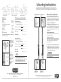
Rebound damping
adjuster
Öhlins front fork Supermotard
Öhlins front fork Supermotard Universal is an up-
side down type front fork. It is fully adjustable and
has adjustment for rebound oil compression
damping. The spring pre-load is also adjustable.
Compression damping adjuster
The high and low speed compression adjuster is
located at the bottom of the fork leg.
High speed adjustments are made by turning
the nut. Use a 12 mm socket. Low speed adjust-
ments are made by turning the screw. Use a slot
screw driver.
Rebound damping adjuster
Adjustments are made at the top of the fork leg.
Use a flat screw driver.
Spring pre-load adjuster
Adjustments are made by turning the nut at the top
of the fork leg. Clockwise for harder adjustment,
counter clockwise too release the pre-load.
Use a 17 mm key.
The adjusters have a normal right hand tread. Turn
the damping adjusters clockwise to fully closed (pos.
zero [0]). Turn counter clockwise to open and count
the clicks until you reach the recommended number
of clicks. See Setup data at page 8.
CAUTION!
Do not use too much force, delicate sealing sur-
faces can be damaged.
Spring preload
adjuster
Low speed
compression
adjustment
High speed
compression
adjustment
Checking sag and ride height
Front suspension
F1. Bike on a stand with the
suspension fully extended = ............
F2. Bike on the ground without rider = ............
F3. Bike on the ground with rider = ............
Free sag
F1 - F2 = ............
Ride height
F1 - F3 = ............
Rear suspension
R1.Bike on a stand with the
suspension fully extended = ............
R2.Bike on the ground without rider = ........... .
R3.Bike on the ground with rider = ............
Free sag
R1 - R2 = ............
Ride height
R1 - R3 = ............
NOTE!
If ride height is higher than recommended,
softer spring/springs must be used.
If ride height is lower than recommended,
harder spring/springs must be used.
Contact your Öhlins dealer for advice.
Öhlins Racing AB, Box 722, S-194 27 Upplands Väsby, Sweden.
Phone +46 8 590 025 00. Fax +46 8 590 025 80.
www.ohlins.com
Part No. FG 461. Issued 04 03 03
Setup data
Length 910 mm
Stroke 255 mm
Rebound adj 12 clicks
Compression damping adjuster
Low speed 14 clicks
High speed 1 turn
Pre-load
.........
mm*
Fork position
.........
mm
Oil level 100 mm
Free spring length 436 mm
* Depending on brand and model. Make a note
after settings are made.
Bike on a stand. Bike on the ground. Bike with rider on.
F1
R1
F2
R2
F3
R3
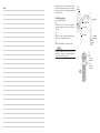
Fork position is
measured from
the top of the fork
leg, to the top
surface of the
triple clamp.
4 mm
Oil level
Oil level is
measured from
the top of the
outer leg, with the
top nut off, the
fork fully
compressed and
no spring
installed.

Öhlins products are subject to continual improve-
ment and development. Consequently, although
these instructions include the most up-to-date
information available at the time of printing, there
may be minor differences between your suspen-
sion and this manual. Please consult your Öhlins
dealer if you have any questions with regard to
the contents of the manual.
NOTE!
During storage and transportation, espe-
cially at high ambient temperature, the oil
and grease used for assembling may run out
inside the packing and damage the
expanded polystyrene packing material. This
is not unusual and is in no way detrimental
to the shock absorber.
Kit contents
Before installing the suspension components,
please check the contents of the kit, listed on
the front page of this instruction. If anything is
missing, contact your Öhlins dealer.
Description Part No. Pcs.
Front fork type FG 461
Spring 4.7 Nm/mm 02490-47 2
Spring 5,1 N/mm 02490-51 2
Spring base valve 50 N/mm 04107-05 2
Pre-load tube 02437-16 2
Fork leg cover 02309-80 1 pair
Bolts for cover, M6x12 02314-01 6
Sticker Öhlins 00197-01 2
Sticker 02332-05 2
Optional Spring Rates
02490-41 4.1 N/mm
02490-43 4.3 N/mm
02490-45 4.5 N/mm
02490-47 4.7 N/mm
02490-49 4.9 N/mm
02490-51 5.1 N/mm
Before installation
Öhlins Racing AB can not be held responsible for
any damage whatsoever to suspension components
or vehicle, or injury to persons, if the instructions for
fitting and maintenance are not followed exactly.
Similarly, the warranty will become null and void if
the instructions are not adhered to.
WARNING!
1. Installing suspension components, that is
not approved by the vehicle manufacturer,
may affect the stability of your vehicle. Öhlins
Racing AB cannot be held responsible for
any personal injury or damage whatsoever
that may occur after fitting the suspension
components. Contact an Öhlins dealer or
other qualified person for advice.
2. Please study and make certain that you
fully understand all the mounting instructions
and the owners manuals before handling this
suspension components kit. If you have any
questions regarding proper installation
procedures, contact an Öhlins dealer or other
qualified person.
3. The vehicle service manual must be
referred to when installing the Öhlins
suspension components
Safety signals
Important information concerning safety is
distinguished in this manual by the
following notations:
The Safety alert symbol means:
Caution! Your safety is involved.
WARNING!
Failure to follow warning instructions
could result in severe or fatal injury
to anyone working with, inspecting or
using the suspension, or to bystanders.
CAUTION!
Caution indicates that special
precautions must be taken to avoid
damage to the suspension.
NOTE!
This indicates information that is of
importance with regard to procedures.
Notes

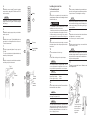
Installing springs
1
Fasten the fork leg in a vice with soft jaws. Un-
screw the top cap, using top cap tool 1761-02 or
1873-01.
2
Remove the top cap from the damper rod ex-
tender, use a 17 and 24 mm wrench.
3
Pull out the damper rod as far as possible.
NOTE!
Closing the compression and the rebound valves
will keep the damper rod extended, making it
easier to install the new spring.
Tool 1761-02
Top cap
Fork leg
17 mm
wrench
24 mm
wrench
1
2
The Öhlins Front Fork 461 is delivered together
with two different sets of springs. It is simpler to
install the springs before mounting the front fork
to the motorcycle.
Front fork
Vice with
soft jaws
Tool
1873-01
Notes

4
Install the the correct spring. Two pairs of springs
are provided – spring ratio 4.7 N/mm and 5.1 N/
mm, respectively.
NOTE!
A spring ratio of 4.9 N/mm is obtained if a 4.7 N/mm
spring is used in one leg and a 5.1 N/mm spring in
the other leg.
5
Reinstall the spring support, the pre-load tube
and the top nut.
6
Install the fork top cap. Tighten (30 Nm) the top
cap and the lock nut against each other, use a
17 and 24 mm wrench.
7
Refit the top cap and tighten. Use top cap tool
1761-02.
The top cap should not be tightened hard, only
turned in position by hand.
8
Adjust the compression and the rebound valves
according to specification card.
Top cap
Pre-load tube
2437-16
17 mm
wrench
24 mm
wrench
Tool
1761-02
5
6
8
Spring
4
Tool
1873-01
WARNING!
1. It’s advisable to have an Öhlins dealer or other
qualified person to fit your front fork.
2. Instructions in the motorcycle workshop manual
are to be followed when removing the front fork.
3. When working on the motorcycle it must be
securely supported to prevent it from falling over.
NOTE!
The clamps mustn´t be overtightended. There is
a risk to deform the fork leg tubes. See the mo-
torcycles Workshop manual for correct torque.
NOTE!
Do not tighten the front wheel axle before the
front legs are aligned. (14)
15
Tighten the wheel axle and check that all items
are tightened to correct torque.
See the motorcycles workshop manual.
16
Refit the removed protecting covers and fit the
Öhlins front leg covers.
Installing the front fork
10
Remove the front wheel, protecting covers and
the brake caliper. Let the caliper stay fitted to the
brake hose.
11
Loosen and remove the fork legs
12
Fit the Öhlins fork legs to the triple clamps.
13
Put the wheel back in position. Reassemble the
brake and fit the hose holder.
17
Continue your work with Owner’s Manual, read
about adjustments.
13
14
The front fork legs
must be aligned
before the front
wheel axle is
tightned
NOTE!
The caliper bracket included is a unversal model
and may not fit the brake caliper. If the bracket is
modified Öhlins Racing can not be held responsi-
ble for any damage whatsoever to front fork or ve-
hicle, or injury to persons.
14
Let the motorcycle stand on the ground and com-
press the front suspension as hard as possible a
couple of times. This will align the fork legs.
NOTE!
Another way to adjust the front legs is to rotate
the front wheel as fast as possible and bring it to
a fast stop by braking. This will bring the legs in
correct position
NOTE!
Make sure that all bolts are tightened in correct torque
and that nothing restrains the front fork when the
suspension is been compressed. Check with the mo-
torcycles workshop manual.
NOTE!
If no tightening torque is given, use the following:
Upper triple clamp: 20 Nm
Lower tripple clamp: 10 Nm
to the motorcycle
9
Put the bike on a stand so the front wheel has
ground clearance. Make sure it´s steadily positioned
and will not fall over.
-
 1
1
-
 2
2
-
 3
3
-
 4
4


Ohlins FG461 Mounting Instruction
- Category
- Motorcycles
- Type
- Mounting Instruction
Ask a question and I''ll find the answer in the document
Finding information in a document is now easier with AI
Related papers
-
Ohlins FG561 Mounting Instruction
-
-
-
-
-
-
-
-
-
