Anchor Audio AN-1000XWPP+ User manual
- Category
- Supplementary music equipment
- Type
- User manual
This manual is also suitable for

MADE IN USA
SIX YEAR WARRANTY
AN-1000X+ Speaker Monitor Owners Manual
MADE IN USA
SIX YEAR WARRANTY
A Message from the President
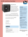
Congratulations on purchasing an Anchor Audio
Speaker Monitor, the choice of thousands of
satisfied customers including the White House,
prestigious universities, school districts nationwide,
police and fire departments, and all branches of the
U.S. Military. Our products are made of the finest
materials and built with pride in the U.S.
We’ve incorporated the latest technology into
your sound system yet kept it simple to use. Just take a few minutes to review this
manual to ensure the maximum enjoyment of your Anchor system. Or, you can view a
demonstration video complete with a trouble shooting section at www.anchoraudio.com.
Feel free to call our friendly customer support staff at 1-800-ANCHOR1
with any questions. We love to hear from our customers.
Janet Jacobs, President
on behalf of all Anchor employees
CONTENTS
GETTING STARTED
Please check your new unit carefully for any
damage which may have occurred during shipment.
Each Anchor product is carefully inspected at the
factory and packed in specially designed boxes for
safe transport.
Notify the freight carrier immediately of any damage
to the shipping box or product. Repack the unit
in the original box and wait for inspection by the
carrier’s claim agent. Notify your dealer of the
pending freight claim.
NOTE: All damage claims must be made with freight carrier!
RETURNING SYSTEMS FOR SERVICE
OR REPAIR
For service or repair, please contact the dealer
you purchased your system from or visit
www.AnchorAudio.com to fill out an
RA
(Return Authorization)
form. If your system is
still under warranty, you will receive an RA Number
with instructions to follow. All shipments to Anchor
Audio must include an RA number and must be
shipped prepaid. C.O.D. shipments and shipments
without an RA number will be refused and returned
at your expense.
IMPORTANT: Save the shipping box & packing materials,
they were specially designed to ship your unit!
1
GETTING STARTED .................................................................................................................. 1
BASIC SYSTEM OPERATION / BALANCED INPUT JACK .............................................................. 2
OPERATING THE BUILT-IN UHF WIRELESS RECEIVER ..................................................................3
OPERATING WIRELESS MICROPHONE/TRANSMITTER .................................................................4
IMPORTANT SAFETY INSTRUCTIONS ........................................................................................ 5
HAVING TROUBLE WITH YOU SOUND SYSTEM? / TECHNICAL SPECS ..........................................6
The AN-1000X+ Speaker Monitor comes with a six year warranty,
the remote comes with a two year warranty, and wireless comes
with a two year warranty.

MADE IN USA
SIX YEAR WARRANTY
AN-1000X+ Speaker Monitor Owners Manual
2
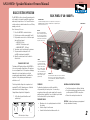
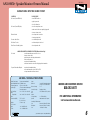
BACK PANEL OF AN-1000XF1+
BASIC SYSTEM OPERATION
The AN-1000X+ is the most versatile powered monitor
on the market, is designed to amplify the signal from a
wide variety of input sources. Use it on an A/V rack, as
a studio monitor, in a trade show booth or on a US Navy
warship, you decide.
Here’s how easy it is to use:
1. Place the AN-1000X+ in desired location
2. Plug the power cord into a grounded AC outlet
3. Plug an audio source into one of the three input
jacks on the back panel:
• LINE IN - RCA jack
• LINE IN - 1/4-inch phone jack
• BALANCED INPUT* - XLR jack
4. Turn volume control on front panel to minimum
5. Set power switch on back panel to ON
(red LED on front panel should light)
6. Adjust the volume, bass & treble controls to
desired levels
SPEAKER OUT
The external speaker output jack
(1/4”-phone, unswitched)
allows the user to power an auxiliary unpowered speaker
(such as the AN-1001X+)
. Minimum 8 ohms impedance for
auxiliary speakers.
POWER SWITCH
LINE OUT
The line-level output provides a
replica of the composite input sig-
nal. Use it for direct recording or
to daisy-chain additional powered
sound systems to the AN-1000X+
for greater crowd coverage.
LINE IN
The line-level inputs
(RCA &
1/4” phone)
are used with
input sources such as VCR’s,
CD players, musical instru-
ments, computers, mixing
consoles, etc. Both inputs
can be used simultaneously
with the AN-1000X+ volume
knob controling composite
program output.
BALANCED INPUT
The balanced XLR input jack can be user configured for a Lo-Z microphone or
bridging balanced line-level inputs. In addition it has 15 volt phantom power
which can be switched on or off.
*BALANCED INPUT JACK
The balanced XLR input jack allows the AN-1000X+
to be used in a variety of applications. The input can
be user configured for a Lo-Z microphone or bridging
balanced line-level inputs
(such as used in the
pro-audio and broadcast industry)
. In addition, the
input has 15 volt phantom power which may be
switched on or off.
The factory default setting is for microphone-level
inputs with 15 volts DC phantom power. Follow the
instructions below to change settings.
Change Balanced Input Jack Configuration
1. Set the three dip switches with a small
pointed object
DIP Switch Option Settings
FEEDBACK
Feedback is a howling noise or shrill sound that is
self-generated by the sound system. It is caused by a
microphone picking up the sound coming from the speaker
and then being re-amplified. Once a feedback loop is started
it will continue until the system is adjusted.
FEEDBACK CAUSES
• Microphone too close, pointing towards or in front of
the speaker
• Volume setting too loud for room
• Sound reflections from hard surfaces, walls, etc.
CAUTION: Feedback can damage your equipment
& may be hazardous to hearing.
AVOIDING & ELIMINATING FEEDBACK
• Point the microphone in a different direction
• Keep the microphone away from the speaker;
position speaker in FRONT of microphone
• Reduce the sound system volume level

MADE IN USA
SIX YEAR WARRANTY
AN-1000X+ Speaker Monitor Owners Manual
CHANNEL SELECTION - BUILT-IN RECEIVER
Select a channel, set the built-in receiver & microphone transmitter
to that channel before using your wireless system.
1. Choose any available wireless channel from 1 thru 16
(see page 4 for transmitter instructions)
2. Set the Wireless Channel Selection Knob to the channel you
choose in step 1
DIVERSITY WIRELESS BY ANCHOR AUDIO
Anchor Audio UHF wireless is a 16 channel, diversity wireless system that receives signals with two independent antennae. With diversity
wireless the receiver processes the stronger signal, effectively minimizing dropouts and interference from other transmitting sources. The
antennae are mounted internally so there are no obstructions or risk of damage. The 8000 series wireless operates between 540 - 570 MHz.
NOTE: Ongoing wireless interference? The frequency you selected may be in use by other systems in the area.
Change channels until you find a clear frequency.
If you have two wireless receivers repeat above for the second receiver.
Remember, each receiver/transmitter pair must be set to different
channels to avoid interference.
NOTE: If you experience ongoing interference with your wireless system, the selected frequency may be incompatible with other systems in the area.
Try different channels to find a clear frequency.
CONTROLLING FEEDBACK
Feedback, a howling noise or shrill sound, is
self-generated by the sound system. It’s caused
by a microphone picking up the sound coming
from the speaker and then re-amplifying it. Once
a feedback loop starts, it continues until the
system is adjusted.
FEEDBACK CAUSES
• Microphone too close, pointing towards
or in front of speaker
• Volume setting is too loud for room
• Sound reflecting off hard surfaces
AVOIDING & ELIMINATING FEEDBACK
• Point microphone in a different direction
• Keep microphone away from the speaker
• Place speaker in FRONT of the microphone
• Reduce the sound system volume levels
CAUTION: Feedback can damage your equipment & may
be hazardous to hearing.
3
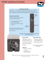
UHF WIRELESS
VOLUME CONTROL
UHF WIRELESS
CHANNEL SELECTION
RX INDICATOR LIGHTS

MADE IN USA
SIX YEAR WARRANTY
AN-1000X+ Speaker Monitor Owners Manual
USING YOUR WIRELESS MICROPHONES
After you have set the transmitter channel (see above) you are ready to use your wireless microphone:
1. Body-pack transmitter users must insert
the mic plug into the transmitter jack marked
MIC
2. Push the transmitter power button for two sec-
onds until ON (The red LED will stay on when
the mic is turned on. If the red LED flashed, the
battery is low)
3. Turn the AN-1000X+ power switch to ON
4. The RX indicators will light
(only one indicator
will light at a time)
when the wireless signal is
being transmitted and received
OPERATING THE WIRELESS MICROPHONE/TRANSMITTER
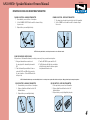
REPLACE BATTERY - HANDHELD TRANSMITTER
1. Unscrew battery cover on bottom of microphone
2. Replace old batteries with two fresh size ‘AA’
alkaline batteries
3. Replace battery cover and tighten firmly
CAUTION: Harmful feedback may occur when walking in front of a sound system or speaker with a wireless microphone. Always point microphone away from speakers.
CHANNEL SELECTION - HANDHELD TRANSMITTER
1. Unscrew battery cover on bottom of microphone
2. Set the CHANNEL SELECTOR dial to match the channel setting
of your receiver
3. Replace battery cover and tighten firmly
NOTE: When using dual wireless, each microphone must be set to a different channel.
CHANNEL SELECTION - BODY-PACK TRANSMITTER
1. The channel selection dial is located on the side of the transmitter
2. Set the CHANNEL selection dial to match the channel setting of
the receiver
REPLACE BATTERY - BODY-PACK TRANSMITTER
1. Slide open battery cover on front of transmitter
2. Replace old batteries with two fresh size ‘AA’
alkaline batteries
3. Replace battery cover by sliding firmly into place
4

MADE IN USA
SIX YEAR WARRANTY
AN-1000X+ Speaker Monitor Owners Manual
5
Important Safety Instructions
1) Read Instructions – All the safety and operation instructions should be read before the
product is operated.
2) Retain Instructions – The safety and operating instructions should be retained for future
reference.
3) Heed Warnings- All warnings on the product and in the operating instructions should be
adhered to.
4) Follow Instructions – All operating and use instructions should be followed.
5) Cleaning – Unplug this product from the wall outlet before cleaning. Do not use liquid
cleaners or aerosol cleaners. Use a damp cloth for cleaning.
Exception: A product that is meant for uninterrupted service and that for some specific
reason, such as the possibility of the loss of an authorization code for the CATV converter,
is not intended to be unplugged by the user for cleaning or any other purpose, may
exclude the reference to unplugging the product in the cleaning description otherwise in
above 5).
6) Attachments – Do not use attachments not recommended by the product manufacturer
as they may cause hazards.
7) Water and Moisture – Do not use this product near water – for example, near a bath tub,
wash bowl, kitchen sink, or laundry tub; in a wet basement; or near a swimming pool;
and the like.
8) Accessories – Do not place this product on an unstable cart, stand, tripod, bracket, or
table. The product may fall, causing serious injury to a child or adult, and serious damage
to the product. Use only with a cart, stand, tripod, bracket, or table recommended by the
manufacturer, or sold with the product. Any mounting of the product should follow the
manufacturer’s instructions, and should use a mounting accessory recommended by the
manufacturer.
9) A product and cart combination should be moved with care. Quick stop, excessive force,
and uneven surfaces may cause the product and cart combination to overturn.
10) Ventilation – Slots and openings in the cabinet are provided for ventilation and to ensure
reliable operation of the product and to protect it from overheating, and these openings
must not be blocked or covered. The openings should never be blocked by placing the
product on a bed, sofa, rug, or other similar surface. This product should not be placed in
a build-in installation such as a bookcase or rack unless proper ventilation is provided or
the manufacturer’s instructions have been adhered to.
11) Power Sources – This product should be operated only from the type of power source
indicated on the marking label. If you are not sure of the type of power supply to your
home, consult your product dealer or local power company. For products intended to
operate from battery power, or other sources, refer to the operating instructions.
12) Grounding or Polarization – This product may be equipped with a polarized alternating-
current line plug (a plug having one blade wider than the other). This plug will fit into
the power outlet only one way. This is a safety feature. IF you are unable to insert the
plug fully into the outlet, try reversing the plug. If the plug should still fail to fit, contact
your electrician to replace your obsolete outlet. Do not defeat the safety purpose of the
polarized plug.
13) Power-Cord Protection – Power-supply cords should be routed so that they are not likely
to be walked on or pinched by items placed upon or against them, paying particular
attention to cords at plugs, convenience receptacles, and the point where they exit from
the product.
14) Protective Attachment Plug – The product is equipped with an attachment plug having
overload protection. This is a safety feature. See Instruction Manual for replacement or
resetting of protective device. If replacement of the plug is required, be sure the service
technician has used a replacement plug specified by the manufacturer that has the same
overload protection as the original plug.
15) Outdoor Antenna Grounding – If an outside antenna or cable system is connected to
the product, be sure the antenna or cable system is grounded so as to provide some
protection against voltage surges and built-up static charges. Article 810 of the National
Electrical Code, ANSI/NFPA 70, provides information with regard to proper grounding of
the mast and supporting structure grounding of the lead in wire to an antenna discharge
unit, size of grounding conductors, location of antenna-discharge unit, connection of
grounding electrodes, and requirements for the grounding electrode. See Figure A.
16) Lightning – For added protection this product during lightning storm, or when it is left
unattended and unused for long periods of time, unplug it from the wall outlet and
disconnect the antenna or cable system. This will prevent damage to the product due to
lightning and power-line surges.
17) Power Lines – An outside antenna system should not be located in the vicinity of
overhead power lines or other electric light or power circuits, or where it can fall into
such power lines or circuits. When installing an outside antenna system, extreme care
should be taken to keep from touching such power lines or circuits as contact with them
might be fatal.
18) Overloading – Do not overload wall outlets, extension cords, or integral convenience
receptacles as this can result in a risk of fire or electric shock.
19) Object and Liquid Entry – Never push objects of any kind into this product through
openings as they may touch dangerous voltage points or short-out parts that could result
in a fire or electric shock. Never spill liquid of any kind on the product.
20) Servicing – Do not attempt to service this product yourself as opening or removing
covers may expose you to dangerous voltage or other hazards. Refer all servicing to
qualified service personnel.
21) Damage Requiring Service – Unplug this product from the wall outlet and refer servicing
to qualified service personnel under the following conditions:
a. When the power-supply cord or plug is damaged.
b. If liquid has been spilled, or objects have fallen into the product.
c. If the product has been exposed to rain or water.
d. If the product does not operate normally by following the operating
instructions. Adjust only those controls that are covered by the operating
instructions as an improper adjustment of other controls may result in damage
and will often require extensive work by a qualified technician to restore the
product to its normal operation.
e. If the product has been dropped or damaged in any way.
f. When the product exhibits a distinct change in performance – this indicates a
need for service.
22) Replacement Parts – When replacement parts are required, be sure the service
technician has used replacement parts specified by the manufacturer or have the same
characteristics as the original part. Unauthorized substitutions may result in fire, electric
shock, or other hazards.
23) Safety Check – Upon completion of any service or repairs to this product, ask the service
technician to perform safety checks to determine that the product is in proper operation
condition.
24) Wall or Ceiling Mounting – The product should be mounted to a wall or ceiling only as
recommended by the manufacturer.
25 Heat – The product should be situated away from heat sources such as radiators, heat
registers, stoves, or other products (including amplifiers) that produce heat.

MADE IN USA
SIX YEAR WARRANTY
AN-1000X+ Speaker Monitor Owners Manual
AN-1000X+ TECHNICAL SPECIFICATIONS
(Specifications Subject to Change Without Notice)
ANCHOR AUDIO CUSTOMER SERVICE
800.262.4671
FOR ADDITIONAL INFORMATION
visit www.anchoraudio.com
6
Rated Power Output 50 watts continuous @ 4W
Max SPL @ Rated Power 107 dB @ 1 meter
Frequency Response 65 Hz – 20 kHz ± 3 dB
Speaker Type 4.5” woofer with shielded magnet,
10mm dome tweeter
AC Power Reqs. 110 – 125Vac, 50/60 Hz, 90W
Max
Export Model 208 – 240Vac, 50/60 Hz, 90W
Max
Dimensions
(HWD)
5.25” x 8.4” x 9”
(13 x 21 x 23 cm)
Weight 9.5 lbs / 4.3 Kg
Tone Controls
Bass +8 – 12 dB @ 100 Hz
Treble +10 – 12 dB @ 10 kHz
Inputs
Balanced female XLR, switchable phantom
power, 15 volts DC @ 6.8 kW
Mic-Level Setting Lo-Z
Line-Level Setting Bridging (10 kW)
Line Hi-Z, unbalanced, 1/4”-phone &
RCA
Outputs
Line (post fader) Lo-Z, buffered, RCA
Speaker 8W, unswitched, 1/4”-phone
Sensitivity For Rated Output
Line balanced -18 dBv (125 mVrms)
Microphone balanced -56 dBv (1.5 mVrms)
Line -18 dBv (125 mVrms)
HAVING TROUBLE WITH YOUR SOUND SYSTEM?
CONDITION POSSIBLE CAUSE
No Sound
(Power LED Not Lit)
• turn POWER switch on
• plug in power cord
• check for blown fuse
No Sound
(Power LED Lights)
• check for output from source
• make sure all cables are completely plugged in
• increase volume control
Distorted Sound • check input cable connection
• lower input signal level
Excessive Hum / Noise • use shielded input cable
Mic Volume Too Low • set balanced input to mic-level
Blows Fuse w/ Auxiliary Speaker • shorted speaker cable
HAVING TROUBLE WITH YOUR WIRELESS SYSTEM?
(Wireless Model Only)
No Sound • confirm transmitter power switch is set to on
• turn up volume control
• plug microphone into body-pack transmitter
• turn sound system on
• replace mic/transmitter battery
• make sure hands free mic cable is fully plugged into transmitter
Frequent Transmitter Dropouts • replace mic/transmitter battery
• move mic/transmitter closer to AN-1000XF1+
• change transmitter to different channel
-
 1
1
-
 2
2
-
 3
3
-
 4
4
-
 5
5
-
 6
6


Anchor Audio AN-1000XWPP+ User manual
- Category
- Supplementary music equipment
- Type
- User manual
- This manual is also suitable for
Ask a question and I''ll find the answer in the document
Finding information in a document is now easier with AI
Related papers
-
Anchor Audio AN-1000X Owner's manual
-
-
Anchor Audio AN135BK User manual
-
-
-
Anchor Audio BBP-7500/HH Owner's manual
-
-
-
Anchor Audio AN-130U1 Owner's manual
-
Anchor Audio Speaker AN-130 User manual
Other documents
-
Anchor AN-1000X+ Owner's manual
-
Audiovox 128-5971 User manual
-
-
-
-
-
-
-
-