Page is loading ...

Page 1
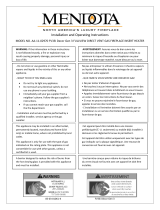
WARNING
FIRE OR EXPLOSION HAZARD
Failure to follow safety warnings exactly
could result in serious injury, death or
property damage.
— Donotstoreorusegasolineorotheram-
mable vapors and liquids in the vicinity of
this or any other appliance.
— WHAT TO DO IF YOU SMELL GAS
• Donottrytolightanyappliance.
• Donottouchanyelectricalswitch;do
not use any phone in your building.
• Leavethebuildingimmediately.
• Immediately call your gas supplier
from a neighbor’s phone. Follow the
gas supplier’s instructions.
• Ifyoucannotreachyourgassupplier,
calltheredepartment.
— Installation and service must be per-
formed by a qualied installer, service
agency or the gas supplier.
INSTALLER:
Leave this manual with the appliance.
CONSUMER:
Retain this manual for future reference.
This appliance may be installed in
an aftermarket, permanently located,
manufactured home (USA only) or mobile
home, where not prohibited by state or
local codes.
This appliance is only for use with the type
of gas indicated on the rating plate. This
appliance is not convertible for use with
othergases,unlessacertiedkitisused.
HOT GLASS
DO NOT TOUCH
NEVER
WILL
CAUSE BURNS.
GLASS
UNTIL COOLED.
ALLOW CHILDREN
TO TOUCH GLASS.
WARNING
A barrier designed to reduce the risk of burns from the
hot viewing glass is provided with this appliance and shall
be installed for the protection of children and other at-risk
individuals.
This replace is design
certied in accordance
with American National
Standard/CSA Standard
ANSI Z21.88/CSA 2.33
and by Underwriters
Laboratories as a Direct
Vent Gas Fireplace
Heater and shall be
installed according to
these instructions.
GAS-FIRED
UL FILE NO. MH30033
INSTALLATION INSTRUCTIONS
DVCP BURNER UPGRADE KIT
37970 - 37987

37989-0-0317Page 2
BURNER UPGRADE KIT INSTALLATION
NOTICE: Do not handle barrier screen or door with your bare
hands! (Always Wear Gloves)
1. Turn off power. Lift barrier screen and pull away from the
unit. See Figure 1.
Figure 1
2. Pull outward to release both latches at bottom of rebox
assembly. See Figure 2.
Figure 2
3. Disengage Glass Frame by pulling outward in a swinging
motion. Place Glass Frame aside in a safe out-of-the-way
location. See Figure 3.
Figure 3
4. Remove log set and decorative media. Remove brackets
and liners if installed. Retain bracket and screws for
reassembly. SeeFigure4.(Reectivelinersshown)
Figure 4

37989-0-0317 Page 3
BURNER UPGRADE KIT INSTALLATION (CONT’D)
5. Remove log support by removing the two screws securing
the metal plate to log support. Retain log support and screws
for reassembly. See Figure 5.
Figure 5
6. Remove the four screws securing burner and slide to right
then lift burner off. Retain burner and screws for reassembly.
See Figure 6.
Figure 6
7. Remove air shutter or burner using 1/4-inch bit. Keep screw
for reassembly.
8. Place air shutter from step 7 onto new burner using the
matching size drill bit. Set the spacing as shown in table
below. Insert screw from step 7.
NATURAL GAS SETTINGS
DVCP32 3/16 inch
DVCP36 3/16 inch
DVCP42 1/8 inch
LP GAS SETTINGS
DVCP32 Full Open
DVCP36 Full Open
DVCP42 Full Open
9. Reinstall the new burner and four screws removed in step 6.
See Figure 6.
10. Reinstall the log support and secure it with metal plate and
two screws removed in step 5. See Figure 5.
11. Add new burner cover.
12.
Add new liner and bracket if removed in step 4. See Figure 4.
13. Add log set and decorative media.
14. Turn on power.
15. Reinstall the glass frame removed in steps 2 and 3. See
Figures 2 and 3.
16. Replace barrier screen removed in step 1. See Figure 1.

37989-0-0317Page 4
www.empirecomfort.com
Empire Comfort Systems Inc.
Belleville, IL
If you have a general question
about our products, please e-mail
us at [email protected].
If you have a service or repair
question, please contact your dealer.
/