Motorola MP6000 Specification
- Category
- Bar code readers
- Type
- Specification

MP6000
INTEGRATOR GUIDE


MP6000
INTEGRATOR GUIDE
72E-172632-05
Revision A
July 2014

ii MP6000 INTEGRATOR GUIDE
© 2013-2014 Motorola Solutions, Inc. All rights reserved.
No part of this publication may be reproduced or used in
any form, or by any electrical or mechanical means,
without permission in writing from Motorola. This includes electronic or mechanical means, such as
photocopying, recording, or information storage and retrieval systems. The material in this manual is subject to
change without notice.
The software is provided strictly on an “as is” basis. All sof
tware, including firmware, furnished to the user is on
a licensed basis. Motorola grants to the user a non-transferable and non-exclusive license to use each
software or firmware program delivered hereunder (licensed program). Except as noted below, such license
may not be assigned, sublicensed, or otherwise transferred by the user without prior written consent of
Motorola. No right to copy a licensed program in whole or in part is granted, except as permitted under
copyright law. The user shall not modify, merge, or incorporate any form or portion of a licensed program with
other program material, create a derivative work from a licensed program, or use a licensed program in a
network without written permission from Motorola. The user agrees to maintain Motorola’s copyright notice on
the licensed programs delivered hereunder, and to include the same on any authorized copies it makes, in
whole or in part. The user agrees not to decompile, disassemble, decode, or reverse engineer any licensed
program delivered to the user or any portion thereof.
Motorola reserves the right to make changes
to any software or product to improve reliability, function, or
design.
Motorola does not assume any product liability
arising out of, or in connection with, the application or use of
any product, circuit, or application described herein.
No license is granted, either expressly or by implicatio
n, estoppel, or otherwise under any Motorola, Inc.,
intellectual property rights. An implied license only exists for equipment, circuits, and subsystems contained in
Motorola products.
MOTOROLA, MOTO, MOTOROLA SOLUTIONS and the S
tylized M Logo are trademarks or registered
trademarks of Motorola Trademark Holdings, LLC and are used under license. All other trademarks are the
property of their respective owners.
Motorola Solutions, Inc.
One Motorola Plaza
Holtsville, New York 11742-1300
http://www.motorolasolutions.com
Warranty
Subject to the terms of Motorola’s hardware warranty statement, the MP6000 is warranted against defects in
workmanship and materials for a period of 1 (one) year from the date of shipment.
For the complete Motorola hardware product warranty statement, go to:
http://www.motorolasolutions.com/warrant
y

iii
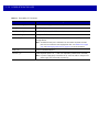
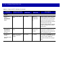
Revision History
Changes to the original guide are listed below:
Change Date Description
-01 Rev A 6/2013 Initial Release.
-02 Rev A 6/2013 Added:
- Figure 3-43, Sensormatic Coil Routing
Updated:
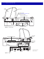
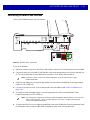
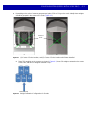
- Figure 1-2, Left Side View
- Figure 3-44, Checkpoint Antenna Installation
- Figure A-2 callouts
- Checkpoint antenna routing color
-03 Rev A 12/2014 Added:
- NCR single cable scanner/scale, NCR scanner
, Datalogic scanner only, and new
RS-232 bar codes.
- Support for third party hand-held scanners
using USB auxiliary ports.
- RS-232 host connection to AUX 2 port (lea
ves USB host port available for future
use).
- Programmable scale initial zero setting range.
- IBM scale 3-byte status support.
- Volume button disable feature.
- Dual cable scale (SASI only).
- Wincor A/B, and RS-232 host interfaces (see Table 2-4 on page 2-15).
- USB HID keyboard interface.
- Drivers License Parsing (some models).
Updated:
- Host interface ports, and cables.
-04 Rev A 5/2014 Added:
- Third Party Scale bar codes.
- Price Computational Scale Interface circuit drawing.
- Mounting frame.
Updated:
- Added information to step 2 on page 4-7.
-05 Rev A 7/2014 Updated:
-Table A-1;
E18, E25, E27 and E30 e
rrors changed to warnings.
-From Act
ive Mode 5.0 average, <12W peak to Active Mode 4.65 average, <12W
peak.

iv MP6000 INTEGRATOR GUIDE

Warranty ......................................................................................................................................... ii
Revision History.............................................................................................................................. iii
About This Guide
Introduction..................................................................................................................................... v
Chapter Descriptions ...................................................................................................................... v
Notational Conventions................................................................................................................... vi
Related Publications....................................................................................................................... vi
Recommended Services Information.............................................................................................. vii
Chapter 1: PRODUCT OVERVIEW AND FEATURES
Introduction .................................................................................................................................... 1-1
Product Overview ........................................................................................................................... 1-2
Configurations ................................................................................................................................ 1-3
Peripherals ..................................................................................................................................... 1-8
Supported Auxiliary Hand-held Scanner .................................................................................. 1-8
EAS Devices ............................................................................................................................ 1-8
Scale Devices .......................................................................................................................... 1-8
USB Flash Drives ..................................................................................................................... 1-8
Customer Side Scanner (CSS) ................................................................................................ 1-8
Features of the MP6000 ................................................................................................................ 1-9
Features Summary .................................................................................................................. 1-13
Chapter 2: HOST INTERFACES AND CABLE PINOUTS
Overview ........................................................................................................................................ 2-1
Interfaces, Components, and Communication ............................................................................... 2-2
POS Interfaces and Host Communication ............................................................................... 2-2
Auxiliary Ports and Peripherals ................................................................................................ 2-2
Programming Management Tools ............................................................................................ 2-3
Application Programming Interfaces ........................................................................................ 2-3
Connecting a USB Interface .......................................................................................................... 2-4
TABLE OF CONTENTS

vi MP6000 INTEGRATOR GUIDE
USB Host Parameters ................................................................................................................... 2-6
USB Device Type ..................................................................................................................... 2-6
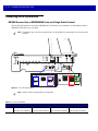
Connecting an RS-232 Interface ................................................................................................... 2-12
MP6000 Scanner Only or MP6200/6500 Scale with Single Cable Protocol ............................ 2-12
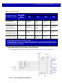
Price Computational Scale Interface Circuit Drawing .............................................................. 2-13
Connect MP6000 to RS-232 Host ............................................................................................ 2-14
MP6000 with a Dual Cable Scanner/Scale .............................................................................. 2-14
RS-232 Parameters ....................................................................................................................... 2-15
RS-232 Host Parameters ............................................................................................................... 2-16
RS-232 Host Types .................................................................................................................. 2-20
RS-232 Host -NCR Variant ................................................................................................ 2-30
RS-232 Host -Datalogic Variant ......................................................................................... 2-31
RS-232 Device Port Configuration ........................................................................................... 2-32
Third Party Scale Parameters .................................................................................................. 2-37
Third Party Scale ............................................................................................................... 2-37
Third Party Scale LED Pin ................................................................................................. 2-39
Third Party Scale Zero Pin ................................................................................................. 2-41
Connecting an IBM RS-485 Interface ............................................................................................ 2-43
IBM RS-485 Host Parameters ....................................................................................................... 2-44
IBM Scale Port Addresses ....................................................................................................... 2-49
Connector Pins .............................................................................................................................. 2-53
RS-232 AUX 1 ................................................................................................................... 2-53
Scale Display Port .............................................................................................................. 2-53
RS-232 AUX 2 ................................................................................................................... 2-54
Checkpoint Interlock .......................................................................................................... 2-54
AUX A-B (Stacked USB) .................................................................................................... 2-54
POS ................................................................................................................................... 2-55
12V DC ............................................................................................................................. 2-55
Chapter 3: SITE PREPARATION AND INSTALLATION
Overview ........................................................................................................................................ 3-1
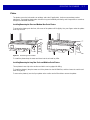
Site Preparation ............................................................................................................................. 3-2
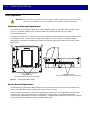
Ventilation and Spacing Requirements .................................................................................... 3-2
Service Access Requirements ................................................................................................. 3-2
Electrical Power Considerations .............................................................................................. 3-3
Grounding .......................................................................................................................... 3-3
Checkstand Preparation .......................................................................................................... 3-4
Liquid Spills and Moisture .................................................................................................. 3-4
Vertical Clearance .............................................................................................................. 3-4
Tools .................................................................................................................................. 3-4
Counter Cutout ................................................................................................................... 3-5
Ergonomics ........................................................................................................................ 3-5
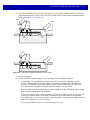
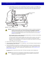
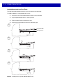
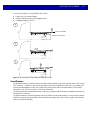
Installing Components ................................................................................................................... 3-6
Quick Reference Installation Steps .......................................................................................... 3-6
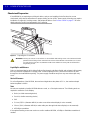
Remove Existing Bioptic Scanner and Accessories ................................................................ 3-7
Unpacking MP6000 Equipment ............................................................................................... 3-7
Pre-Installation Notes ......................................................................................................... 3-8
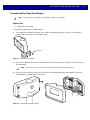
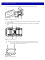
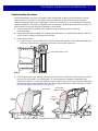
Assemble the Dual Head Scale Display .................................................................................. 3-9
Required Tools ................................................................................................................... 3-9
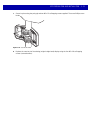
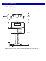
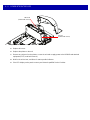
Install the Scale Display ........................................................................................................... 3-12

Table of Contents vii
Getting Started ................................................................................................................... 3-14
Installing ............................................................................................................................. 3-15
Cables and Connections .......................................................................................................... 3-15
Install the Customer Side Scanner (MX101) ............................................................................ 3-16
Installing the MX101 on the Customer’s Right Side (Default) of the Tower Cover ............ 3-17
Installing the MX101 on the Customer’s Left Side of the Tower Cover .............................. 3-21
Affixing the Identification Label .......................................................................................... 3-23
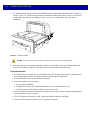
Install the MP6000 /Scale ........................................................................................................ 3-24
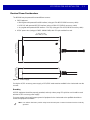
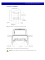
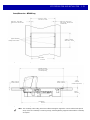
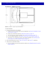
Checkstand Counter Cutouts and MP6000 Dimensions .................................................... 3-24
Cutout/Dimensions - MP6000 Short ................................................................................... 3-25
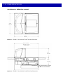
Cutout/Dimensions - MP6000 Short (continued) ................................................................ 3-26
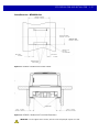
Cutout/Dimensions - MP6000 Medium .............................................................................. 3-27
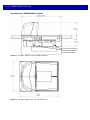
Cutout/Dimensions - MP6000 Long ................................................................................... 3-29
Install Sensormatic Coils .......................................................................................................... 3-33
Install Checkpoint Antenna ...................................................................................................... 3-35
Trim Kit Installation (If Required) ............................................................................................. 3-36
MP6000 Mounting Frame (If Required) ................................................................................... 3-37
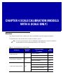
Chapter 4: SCALE CALIBRATION (MODELS WITH A SCALE ONLY)
Overview ........................................................................................................................................ 4-1
Scale Calibration Procedure (Scanner/Scale Configurations Only) ............................................... 4-2
Scale Configurations ................................................................................................................ 4-2
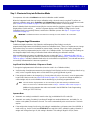
Step 1 - Electronic Entry into Calibration Mode ....................................................................... 4-3
Step 2 - Program Legal Parameters ........................................................................................ 4-3
Legal Scale Units (Unit Selection) - Kilograms or Pounds ................................................. 4-3
Important Notes .................................................................................................................. 4-3
Legal Scale Dampening Filter ............................................................................................ 4-4
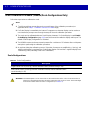
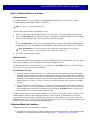
Step 3 - Calibration at NO LOAD ............................................................................................. 4-4
Step 4 - Calibration at LOAD ................................................................................................... 4-4
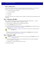
Step 5 - Calibration Success or Failure ................................................................................... 4-7
Calibration Success ........................................................................................................... 4-7
Calibration Failure .............................................................................................................. 4-7
Possible Reasons for a Fail ............................................................................................... 4-7
Calibration Mode Exit Conditions ............................................................................................. 4-7
Verification Test ....................................................................................................................... 4-8
Audit Tallies ............................................................................................................................. 4-11
Scale Configuration Parameters .................................................................................................... 4-12
Legal Scale Units ..................................................................................................................... 4-12
Scale Display Configuration ..................................................................................................... 4-14
Legal Scale Dampening Filter Setting ...................................................................................... 4-16
User Interface Displays and Signals .............................................................................................. 4-20
Chapter 5: OPERATING THE SCANNER
Overview ........................................................................................................................................ 5-1
Controls and Indicators .................................................................................................................. 5-2
LED Array Bar .......................................................................................................................... 5-2
Diagnostic LED/7-segment Display ......................................................................................... 5-3
Front Panel Buttons ................................................................................................................. 5-4
The three front panel user interface buttons are backlit for ease of use. ........................... 5-4

viii MP6000 INTEGRATOR GUIDE
Scale Zero Button (Configurations with Scale Only) .......................................................... 5-4
Volume/Tone Control Button .............................................................................................. 5-4
Sensormatic Manual Activation and Sensormatic Status Button ....................................... 5-5
Soft Reset Buttons ............................................................................................................. 5-5
MP6000 Related Hardware ........................................................................................................... 5-6
Scale Display (Scanner/Scale Configurations Only) ................................................................ 5-6
Scale (Scanner/Scale Configurations Only) ............................................................................. 5-6
Single Interval Range Scales ............................................................................................. 5-6
Dual Interval Range Scales ............................................................................................... 5-6
Customer Side Scanner (CSS) - Optional ............................................................................... 5-6
Platter ....................................................................................................................................... 5-7
Installing/Removing the Short and Medium Non-Scale Platters ........................................ 5-7
Installing/Removing the Long Non-Scale and Medium Scale Platters ............................... 5-7
Installing/Removing the Long Scale Platter ....................................................................... 5-8
Scan Windows ......................................................................................................................... 5-9
Operating Modes ........................................................................................................................... 5-10
Programming the MP6000 ............................................................................................................. 5-10
Programming Management tools ............................................................................................. 5-10
Application Programming Interfaces ........................................................................................ 5-10
Programming Bar Codes ......................................................................................................... 5-10
USB Staging Flash Drive ............................................................................................................... 5-11
MP6000 Menu Structure for the USB Staging Flash Drive ...................................................... 5-11
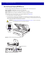
Manually Staging/Configuring MP6000 Devices ...................................................................... 5-12
Loading Cloning Files ........................................................................................................ 5-13
123Scan2 Staging Flash Drive Configuration .......................................................................... 5-14
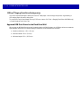
Approved USB Flash Drives for the Flash Drive Well .............................................................. 5-14
Scanning ........................................................................................................................................ 5-15
Weighing Items .............................................................................................................................. 5-16
Electronic Article Surveillance (EAS) ............................................................................................. 5-17
Supported EAS Controllers ...................................................................................................... 5-17
EAS Operating Modes and Settings ........................................................................................ 5-17
Checkpoint Controller .............................................................................................................. 5-18
Sensormatic Controller ............................................................................................................ 5-18
Sensormatic EAS Hard Tags ................................................................................................... 5-18
Sensormatic EAS Soft Tags (Labels) ...................................................................................... 5-19
Beeper and LED Conditions .......................................................................................................... 5-20
Chapter 6: 123SCAN2
Introduction .................................................................................................................................... 6-1
Communication with 123Scan2 ..................................................................................................... 6-1
123Scan2 Requirements ............................................................................................................... 6-2
Scanner SDK, Other Software Tools, and Videos ......................................................................... 6-2
Appendix A: MAINTENANCE, TROUBLESHOOTING, AND ERROR CODES
Overview ........................................................................................................................................ A-1
Maintenance .................................................................................................................................. A-1
Troubleshooting ............................................................................................................................. A-2
Diagnostic LED 7-segment Display - Error and Warning Codes ............................................. A-2
LED Display Notes ................................................................................................................... A-2

Table of Contents ix
Status Indicator Light ............................................................................................................... A-2
Troubleshooting Assistance ..................................................................................................... A-3
General Error and Warning Codes .......................................................................................... A-5
Scale Warning Codes .............................................................................................................. A-6
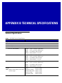
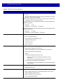
Appendix B: TECHNICAL SPECIFICATIONS
Technical Specifications ................................................................................................................ B-1
Appendix C: HOST INTERFACE CHARACTER SETS
Introduction .................................................................................................................................... C-1
RS-232 Character Sets .................................................................................................................. C-2
Appendix D: PARAMETER DEFAULT TABLE
Index

x MP6000 INTEGRATOR GUIDE

ABOUT THIS GUIDE
Introduction
The MP6000 Integrator Guide provides information on installing, operating, and programming the MP6000.
Chapter Descriptions
Following are brief descriptions of each chapter in this guide.
•
Chapter 1, PRODUCT OVERVIEW AND FEATURES provides an overview of the MP6000 including
configurations, peripherals, and features.
•
Chapter 2, HOST INTERFACES AND CABLE PINOUTS describes the host interfaces supported by the
MP6000, how to connect the MP6000 to a host, setup, and cable
pin-outs. It also includes host interface bar
codes.
•
Chapter 3, SITE PREPARATION AND INSTALLATION describes how to install the MP6000 into a counter
top.
•
Chapter 4, SCALE CALIBRATION (MODELS WITH A SCALE ONLY) describes how to change weight
measurement, calibrate the scale, verify calibration, and recognize errors.
•
Chapter 5, OPERATING THE SCANNER describes how to operate the MP6000 including buttons, switches,
LED indicators, and scanning.
•
Chapter 6, 123SCAN2 provides information about configuring the MP6000 using the 123Scan
2
utility.
•
Appendix A, MAINTENANCE, TROUBLESHOOTING, AND ERROR CODES provides error/warning codes,
troubleshooting, and maintenance information.
•
Appendix B, TECHNICAL SPECIFICATIONS provides technical information about the MP6000.
•
Appendix C, HOST INTERFACE CHARACTER SETS provides ASCII character sets for some host
interfaces.
Notational Conventions
This document uses these conventions:

vi MP6000 INTEGRATOR GUIDE
•
“User” refers to anyone operating the device.
•
“Device” refers to the MP6000.
•
Italics are used to highlight specific items in the general text, and to identify chapters and sections in this
and related documents. It also identifies names of windows, menus, menu items, and fields within
windows.
•
Bold identifies buttons, and switches to be tapped or clicked, and bar code names.
•
Bullets (•) indicate:
• list
s of alternatives or action items.
• lists of required steps that are not necessarily sequential.
•
Numbered lists indicate a set of sequential steps, i.e., those that describe step-by-step procedures.
Related Publications
Following is a list of documents that provide additional information about configuring the MP6000:
•
MP6000 BAR CODE PROGRAMMING GUIDE,
p/n 72E-172633-xx, provides bar codes for MP6000 configuration.
•
MX101 PRODUCT REFERENCE GUIDE, p/n 72E-171320-xx, provides general instructions for setting
up, operating, maintaining, and troubleshooting the MX101 digital scanner.
•
MP6000 MULTI-PLANE IMAGING SCANNER REGULATORY GUIDE, p/n 72-171321-xx, provides
domestic and international regulatory information.
•
Advanced Data Formatting Programmer Guide, p/n 72E-69680-xx, provides information on ADF, a
means of customizing data before transmission to a host.
For the latest version of this guide and all Motorola Solutions
guides, go to:
http://www.motorolasolutions.com/support
Recommended Services Information
If you have a problem using the equipment, contact your facility's technical or systems support. If there is a
problem with the equipment, they will contact the Motorola Solutions Global Customer Support Center at:
http://www.motorolasolutions.com/support
NOTE This symbol indicates something of special interest to the reader. Failure to read the note will not result in
physical harm to the bar code reader, equipment or data.
IMPORTANT This symbol indicates something of importance to the reader. Failure to read the note may impair
the equipment or data.
CAUTION This symbol indicates that if this information is ignored, the possibility of data or material damage
may occur.
WARNING! This symbol indicates that if this information is ignored the possibility that serious
personal injury may occur.

About This Guide vii
When contacting Motorola Solutions support, please have the following information available:
•
Serial number of the unit
•
Model number or product name
•
Software type and version number (if available).
Motorola responds to calls by e-mail, telephone or fax within the time limits set forth in service agreements.
If your problem cannot be solved by the Motorola Solutions Global Customer Support Center, you may need to
return
your equipment for servicing and will be given specific directions, a Field Service Technician from
Motorola, or your authorized service provider may be sent to your location to perform the repair, depending on
your level of entitlement set forth in the service agreement. Motorola is not responsible for any damages
incurred during shipment if the approved shipping container is not used. Shipping the units improperly can
possibly void the warranty.
If you purchased your business product from a Motorola business partner, please contact that business partner
for
support.
Motorola recommends the following Service options to
keep the MP6000 operating at peak performance
throughout its lifecycle:
•
Service from the Start with Advance Exchange Support (available for scanner-only configurations).
•
Service from the Start with On Site System Support (available for scanner-only and scanner/scale
configurations).
•
Motorola also offers service support through authorized resellers who qualify as authorized service
partners.

viii MP6000 INTEGRATOR GUIDE


1 - 2 MP6000 INTEGRATOR GUIDE
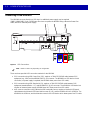
Product Overview
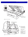
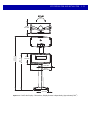
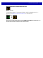
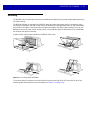
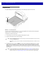
The MP6000 is a data capture solution that uses a sophisticated optical arrangement to view six sides of an
object as it passes through the scanning area. Bar code data is transmitted to a Point-Of-Sale (POS) host via
USB, RS-232, or RS-485. Auxiliary device support includes USB and RS-232 hand-held scanners, Checkpoint
and Sensormatic Electronic Article Surveillance (EAS), scale and optional Scale Display (varies with the
model), USB staging flash drive (memory stick), as well as an optional Customer Side Scanner (2D imager)
that may be mounted into the tower.
The MP6000 is designed to be embedded in a cutout in the retail checkstand.
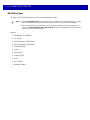
Features include:
•
Six sided scanning
• Rea
ds top-bottom, left-right, and cashier-customer side bar codes
• Omni-directional symbol orientation.
•
Optional integrated scale (single/dual interval).
•
Optional Checkpoint EAS antenna.
•
Optional integrated Sensormatic EAS coil antennas.
•
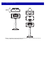
Optional Scale Display (single/dual head) for scale installations.
•
Auxiliary scanner support (USB and RS-232).
•
High swipe speed for increased throughput.
•
User interface (LED indicators, touch controls, audio).
•
Aggressive scanning performance on high density, truncated, and poorly printed bar codes.
•
2D scanning (PDF, Aztec etc.) in both vertical and horizontal windows, or all six-sided orientations.
•
Mobile bar code scanning (cell phone) in both vertical and horizontal windows, or all six-sided
orientations.
•
Optional integrated Customer Side Scanner (CSS) [1D/2D support].
•
Scanner Management Service (SMS), and 123Scan² support enables remote configuration and
monitoring attached peripherals.

PRODUCT OVERVIEW AND FEATURES 1 - 3
Configurations
The MP6000 captures printed or mobile 1D or 2D bar codes. An optional customer-side scanner (CSS) can be
added for bar codes displayed on mobile phones, traditional loyalty cards, or item bar codes. Hand-held
scanner, integrated EAS, and scale support is also available.
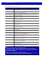
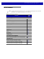
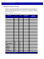
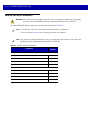
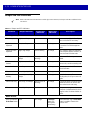
This guide covers the configurations listed in Table 1-1.
NOTE 1. All configurations of the MP6000 include a sapphire glass horizontal platter.
2. New scale configurations are added continually. If you don’t see your country listed, call your
Motorola Solutions office.
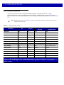
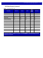
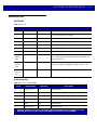
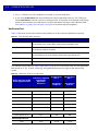
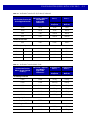
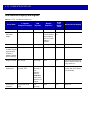
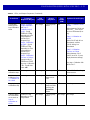
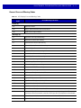
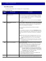
Table 1-1
MP6000 Configurations
Configuration Description
MP6000-LN000M010US Multi-plane scanner, long, with Checkpoint, worldwide.
MP6000-LP000M010US Multi-plane scanner, long, with Checkpoint, with DL Parsing, US/CA.
MP6000-MN000M010US Multi-plane scanner, medium, with Checkpoint, worldwide.
MP6000-MP000M010US Multi-plane scanner, medium, with Checkpoint, with DL Parsing, US/CA.
MP6000-SN000M010US Multi-plane scanner, short, with Checkpoint, worldwide.
MP6000-SP000M010US Multi-plane scanner, short, with Checkpoint, with DL Parsing, US/CA.
MP6010-LN000M010US Multi-plane scanner, long, with Checkpoint, with CSS, worldwide.
MP6010-LP000M010US Multi-plane scanner, long, with Checkpoint, with D
L Parsing, US/CA.
MP6010-MN000M010US Multi-plane scanner, medium, with Checkpoint, with CSS, worldwide.
MP6010-MP000M010US Multi-plane scanner, medium, with Checkpoint, with DL Parsing, US/CA.
MP6010-SN000M010US Multi-plane scanner, short, with Check
point, with CSS, worldwide.
MP6010-SP000M010US Multi-plane scanner, short, with Checkpoint, with DL Parsing, US/CA.
MP6200-LN000M010AU Multi-plane scanner, long, with single inter
val scale, with Checkpoint, scale for
Australia/NZ/SA.
MP6200-LN000M010CM Multi-plane scanner, long, single inter
val kg scale, no CSS, Checkpoint,
Canada-Mexico scale label.
MP6200-LN000M010EU
Multi-plane scanner, long, with single interval scale, with Checkpoint, scale for
EU countries.
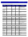
Notes:
1. EU scales are legally accepted in the following countries:
Austria, Belgium, Bulgaria, Cyprus, Czech Republic, Denmark, Estonia, Finland, France,
Germany, Greece, Hungary, Ireland, Iceland, Italy, Liechtenstein, Lithuania, Luxembourg, Latvia,
Malta, Netherlands, Norway, Poland, Portugal, Romania, Slovak Republic, Spain, Sweden,
Switzerland, United Kingdom
2. OIML scales are legally accepted in the following countries:
Barbados, Belize, Bermuda, Chile, Colombia, Costa Rica, El Salvador, Guatemala, Hong Kong,
Jamaica, Saint Lucia, Philippines, Thailand, Trinidad and Tobago, Vietnam

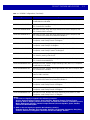
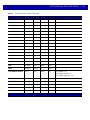
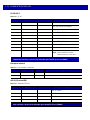
1 - 4 MP6000 INTEGRATOR GUIDE
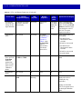
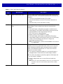
MP6200-LN000M010NN Multi-plane scanner, long, with single interval scale, with Checkpoint, scale for
OIML countries.
MP6200-LN000M010US Multi-plane scanner, long, with single inter
val scale, with Checkpoint, scale for
US/Puerto Rico/Guam/USVI/British VI.
MP6200-LN000M01ABE Multi-plane scanner, Long with single interva
l kg scale, with Checkpoint, scale
Gravity Zone A for Belgium.
MP6200-LN000M01BBE Multi-plane scanner, Long with single interva
l kg scale, with Checkpoint, scale
Gravity Zone B for Belgium.
MP6200-LN000M01CBE Multi-plane scanner, Long with single interva
l kg scale, with Checkpoint, scale
Gravity Zone C for Belgium.
MP6200-LP000M010US Multi-plane scanner, long, with single interv
al scale, with Checkpoint, with DL
parsing, scale for US.
MP6200-MN000M010AU Multi-plane scanner, medium, with single interval scale, with Checkpoint, scale
for Australia/NZ/SA.
MP6200-MN000M010CM Multi-plane scanner, medium, single interva
l kg scale, no CSS, Checkpoint,
Canada-Mexico scale label.
MP6200-MN000M010EU Multi-plane scanner, medium, with single interval scale, with Checkpoint, scale
f
or EU countries.
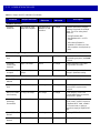
MP6200-MN000M010NN Multi-plane scanner, medium, with single interval scale, with Checkpoint, scale
fo
r OIML countries.
MP6200-MN000M010US Multi-plane scanner, medium, with single interval scale, with Checkpoint, scale
f
or US/Puerto Rico/Guam/USVI/British VI.
MP6200-MN000M01ABE Multi-plane scanner, Medium with single
interval kg scale, with Checkpoint,
scale Gravity Zone A for Belgium.
MP6200-MN000M01BBE Multi-plane scanner, Medium with single
interval kg scale, with Checkpoint,
scale Gravity Zone B for Belgium.
MP6200-MN000M01CBE Multi-plane scanner, Medium with single
interval kg scale, with Checkpoint,
scale Gravity Zone C for Belgium.
MP6200-MP000M010US Multi-plane scanner, medium, with single inter
val scale, with Checkpoint, with
DL parsing, scale for US.
MP6210-LN000M010AU Multi-plane scanner, long, with single interval scale, with Checkpoint, with
CS
S, scale for Australia/NZ/SA.
Table 1-1
MP6000 Configurations (Continued)
Configuration Description
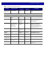
Notes:
1. EU scales are legally accepted in the following countries:
Austria, Belgium, Bulgaria, Cyprus, Czech Republic, Denmark, Estonia, Finland, France,
Germany, Greece, Hungary, Ireland, Iceland, Italy, Liechtenstein, Lithuania, Luxembourg, Latvia,
Malta, Netherlands, Norway, Poland, Portugal, Romania, Slovak Republic, Spain, Sweden,
Switzerland, United Kingdom
2. OIML scales are legally accepted in the following countries:
Barbados, Belize, Bermuda, Chile, Colombia, Costa Rica, El Salvador, Guatemala, Hong Kong,
Jamaica, Saint Lucia, Philippines, Thailand, Trinidad and Tobago, Vietnam
Page is loading ...
Page is loading ...
Page is loading ...
Page is loading ...
Page is loading ...
Page is loading ...
Page is loading ...
Page is loading ...
Page is loading ...
Page is loading ...
Page is loading ...
Page is loading ...
Page is loading ...
Page is loading ...
Page is loading ...
Page is loading ...
Page is loading ...
Page is loading ...
Page is loading ...
Page is loading ...
Page is loading ...
Page is loading ...
Page is loading ...
Page is loading ...
Page is loading ...
Page is loading ...
Page is loading ...
Page is loading ...
Page is loading ...
Page is loading ...
Page is loading ...
Page is loading ...
Page is loading ...
Page is loading ...
Page is loading ...
Page is loading ...
Page is loading ...
Page is loading ...
Page is loading ...
Page is loading ...
Page is loading ...
Page is loading ...
Page is loading ...
Page is loading ...
Page is loading ...
Page is loading ...
Page is loading ...
Page is loading ...
Page is loading ...
Page is loading ...
Page is loading ...
Page is loading ...
Page is loading ...
Page is loading ...
Page is loading ...
Page is loading ...
Page is loading ...
Page is loading ...
Page is loading ...
Page is loading ...
Page is loading ...
Page is loading ...
Page is loading ...
Page is loading ...
Page is loading ...
Page is loading ...
Page is loading ...
Page is loading ...
Page is loading ...
Page is loading ...
Page is loading ...
Page is loading ...
Page is loading ...
Page is loading ...
Page is loading ...
Page is loading ...
Page is loading ...
Page is loading ...
Page is loading ...
Page is loading ...
Page is loading ...
Page is loading ...
Page is loading ...
Page is loading ...
Page is loading ...
Page is loading ...
Page is loading ...
Page is loading ...
Page is loading ...
Page is loading ...
Page is loading ...
Page is loading ...
Page is loading ...
Page is loading ...
Page is loading ...
Page is loading ...
Page is loading ...
Page is loading ...
Page is loading ...
Page is loading ...
Page is loading ...
Page is loading ...
Page is loading ...
Page is loading ...
Page is loading ...
Page is loading ...
Page is loading ...
Page is loading ...
Page is loading ...
Page is loading ...
Page is loading ...
Page is loading ...
Page is loading ...
Page is loading ...
Page is loading ...
Page is loading ...
Page is loading ...
Page is loading ...
Page is loading ...
Page is loading ...
Page is loading ...
Page is loading ...
Page is loading ...
Page is loading ...
Page is loading ...
Page is loading ...
Page is loading ...
Page is loading ...
Page is loading ...
Page is loading ...
Page is loading ...
Page is loading ...
Page is loading ...
Page is loading ...
Page is loading ...
Page is loading ...
Page is loading ...
Page is loading ...
Page is loading ...
Page is loading ...
Page is loading ...
Page is loading ...
Page is loading ...
Page is loading ...
Page is loading ...
Page is loading ...
Page is loading ...
Page is loading ...
Page is loading ...
Page is loading ...
Page is loading ...
Page is loading ...
Page is loading ...
Page is loading ...
Page is loading ...
Page is loading ...
Page is loading ...
Page is loading ...
Page is loading ...
Page is loading ...
Page is loading ...
Page is loading ...
Page is loading ...
Page is loading ...
Page is loading ...
Page is loading ...
Page is loading ...
Page is loading ...
Page is loading ...
Page is loading ...
Page is loading ...
Page is loading ...
Page is loading ...
Page is loading ...
Page is loading ...
Page is loading ...
Page is loading ...
Page is loading ...
Page is loading ...
Page is loading ...
-
 1
1
-
 2
2
-
 3
3
-
 4
4
-
 5
5
-
 6
6
-
 7
7
-
 8
8
-
 9
9
-
 10
10
-
 11
11
-
 12
12
-
 13
13
-
 14
14
-
 15
15
-
 16
16
-
 17
17
-
 18
18
-
 19
19
-
 20
20
-
 21
21
-
 22
22
-
 23
23
-
 24
24
-
 25
25
-
 26
26
-
 27
27
-
 28
28
-
 29
29
-
 30
30
-
 31
31
-
 32
32
-
 33
33
-
 34
34
-
 35
35
-
 36
36
-
 37
37
-
 38
38
-
 39
39
-
 40
40
-
 41
41
-
 42
42
-
 43
43
-
 44
44
-
 45
45
-
 46
46
-
 47
47
-
 48
48
-
 49
49
-
 50
50
-
 51
51
-
 52
52
-
 53
53
-
 54
54
-
 55
55
-
 56
56
-
 57
57
-
 58
58
-
 59
59
-
 60
60
-
 61
61
-
 62
62
-
 63
63
-
 64
64
-
 65
65
-
 66
66
-
 67
67
-
 68
68
-
 69
69
-
 70
70
-
 71
71
-
 72
72
-
 73
73
-
 74
74
-
 75
75
-
 76
76
-
 77
77
-
 78
78
-
 79
79
-
 80
80
-
 81
81
-
 82
82
-
 83
83
-
 84
84
-
 85
85
-
 86
86
-
 87
87
-
 88
88
-
 89
89
-
 90
90
-
 91
91
-
 92
92
-
 93
93
-
 94
94
-
 95
95
-
 96
96
-
 97
97
-
 98
98
-
 99
99
-
 100
100
-
 101
101
-
 102
102
-
 103
103
-
 104
104
-
 105
105
-
 106
106
-
 107
107
-
 108
108
-
 109
109
-
 110
110
-
 111
111
-
 112
112
-
 113
113
-
 114
114
-
 115
115
-
 116
116
-
 117
117
-
 118
118
-
 119
119
-
 120
120
-
 121
121
-
 122
122
-
 123
123
-
 124
124
-
 125
125
-
 126
126
-
 127
127
-
 128
128
-
 129
129
-
 130
130
-
 131
131
-
 132
132
-
 133
133
-
 134
134
-
 135
135
-
 136
136
-
 137
137
-
 138
138
-
 139
139
-
 140
140
-
 141
141
-
 142
142
-
 143
143
-
 144
144
-
 145
145
-
 146
146
-
 147
147
-
 148
148
-
 149
149
-
 150
150
-
 151
151
-
 152
152
-
 153
153
-
 154
154
-
 155
155
-
 156
156
-
 157
157
-
 158
158
-
 159
159
-
 160
160
-
 161
161
-
 162
162
-
 163
163
-
 164
164
-
 165
165
-
 166
166
-
 167
167
-
 168
168
-
 169
169
-
 170
170
-
 171
171
-
 172
172
-
 173
173
-
 174
174
-
 175
175
-
 176
176
-
 177
177
-
 178
178
-
 179
179
-
 180
180
-
 181
181
-
 182
182
-
 183
183
-
 184
184
-
 185
185
-
 186
186
-
 187
187
-
 188
188
-
 189
189
-
 190
190
-
 191
191
-
 192
192
-
 193
193
-
 194
194
-
 195
195
-
 196
196
-
 197
197
-
 198
198
-
 199
199
-
 200
200


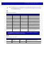
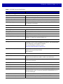
Motorola MP6000 Specification
- Category
- Bar code readers
- Type
- Specification
Ask a question and I''ll find the answer in the document
Finding information in a document is now easier with AI
Related papers
-
Motorola MP6000 Specification
-
Motorola DS4208 Quick start guide
-
-
-
-
-
-
-
-
Other documents
-
-
Datalogic MAGELLAN 8300 Owner's manual
-
Mettler Toledo BC Scales-Dual Display Installation guide
-
Metrologic Stratos MS2x20 Series User manual
-
Dell OptiPlex HUB Owner's manual
-
-
LAB Gruppen LUCIA 60/2 Quick start guide
-
-
 Atron Systems LS-100 Quick Replacement Instructions
-
NCR 7882 Installation and Owner's Manual
