Ryobi EWS1150RS Owner's manual
- Category
- Circular saws
- Type
- Owner's manual

EN
USER’S MANUAL 1
FR
MANUEL D’UTILISATION 5
DE
BEDIENUNGSANLEITUNG 9
ES
MANUAL DE UTILIZACIÓN 13
IT
MANUALE D’USO 17
NL
GEBRUIKSHANDLEIDING 21
PT
MANUAL DE UTILIZAÇÃO 25
DA
BRUGERVEJLEDNING 29
SV
INSTRUKTIONSBOK 33
FI
KÄYTTÄJÄN KÄSIKIRJA 37
NO
BRUKSANVISNING 41
RU
РУКОВОДСТВО ПО ЭКСПЛУАТАЦИИ 45
PL
INSTRUKCJA OBSŁUGI 49
CS
NÁVOD K OBSLUZE 53
HU
HASZNÁLATI ÚTMUTATÓ 57
RO
MANUAL DE UTILIZARE 61
LV
LIETOTĀJA ROKASGRĀMATA 65
LT
NAUDOJIMO VADOVAS 69
ET
KASUTAJAJUHEND 73
HR
KORISNIČKI PRIRUČNIK 77
SL
UPORABNIŠKI PRIROČNIK 81
SK
NÁVOD NA POUŽITIE 85
EL
ΟΔΗΓΙΕΣ ΧΡΗΣΗΣ 89
TR
KULLANiM KILAVUZU 93
1150W 55MM CIRCULAR SAW
SCIE CIRCULAIRE 55MM 1150W
1150W 55MM KREISSÄGE
SIERRA CIRCULAR 55MM 1150W
MOTOSEGA CIRCOLARE DA 1150W 55MM
1150W 55M CIRKELZAAGMACHINE
SERRA CIRCULAR 55MM DE 1150W
1150W 55MM RUNDSAV
CIRKELSÅG 55 MM/1150W
1150 W 55 MM PYÖRÖSAHA
1150 W 55 MM SIRKELSAG
ЦИРКУЛЯРНАЯ ПИЛА, 55 ММ, 1150 ВТ
PILARKA TARCZOWA 1150 W, 55 MM
1150 W 55MM ROTAČNÍ PILA
1150 W-OS 55 MM-ES KÖRFŰRÉSZ
FERĂSTRĂU CIRCULAR 55 MM 1150 W
1150 W 55 MM RIPZĀĢIS
1150 W 55 MM DISKINIS PJŪKLAS
KETASSAAG 55 MM 1150 W
CIRKULAR 55 MM OD 1150 W
1150 W 55 MM KROŽNA ŽAGA
1150W 55 MM KOTÚČOVÁ PÍLA
1150W 55MM ΚΥΚΛΙΚΟΣ ΚΟΠΤΗΣ
"1150W 55 MM DAIRE TESTERE
EWS1150RS
EN ORIGINAL INSTRUCTIONS | FR TRADUCTION DES INSTRUCTIONS ORIGINALES | DE ÜBERSETZUNG DER ORIGINALANLEITUNG | ES TRADUCCIÓN DE LAS
INSTRUCCIONES ORIGINALES | IT TRADUZIONE DELLE ISTRUZIONI ORIGINALI | NL VERTALING VAN DE ORIGINELE INSTRUCTIES | PT TRADUÇÃO DAS INSTRUÇÕES
ORIGINAIS | DA OVERSÆTTELSE AF DE ORIGINALE INSTRUKTIONER | SV ÖVERSÄTTNING AV DE URSPRUNGLIGA INSTRUKTIONERNA | FI ALKUPERÄISTEN
OHJEIDEN SUOMENNOS | NO OVERSETTELSE AV DE ORIGINALE INSTRUKSJONENE | RU ПЕРЕВОД ОРИГИНАЛЬНЫХ ИНСТРУКЦИЙ | PL TŁUMACZENIE INSTRUKCJI
ORYGINALNEJ | CS PŘEKLAD ORIGINÁLNÍCH POKYNŮ | HU AZ EREDETI ÚTMUTATÓ FORDÍTÁSA | RO TRADUCEREA INSTRUCŢIUNILOR ORIGINALE | LV TULKOTS
NO ORIĢINĀLĀS INSTRUKCIJAS | LT ORIGINALIŲ INSTRUKCIJŲ VERTIMAS | ET ORIGINAALJUHENDI TÕLGE | HR PRIJEVOD ORIGINALNIH UPUTA | SL PREVOD
ORIGINALNIH NAVODIL | SK PREKLAD ORIGINÁLNEHO NÁVODU | EL ΜΕΤΑΦΡΑΣΗ ΤΩΝ ΠΡΩΤΟΤΥΠΩΝ ΟΔΗΓΙΩΝ | TR ORIJINAL TALIMATLARIN TERCÜMESI

Fig. 1
Fig. 5
Fig. 3
Fig. 2
Fig. 6
Fig. 4
9
8
8
6
2
1
12
11
10
12
11
13
7
14
10
7
21
22
4
5
3
11
15
1
4
1

Fig. 7
Fig. 9
Fig. 8
Fig. 10
15
18
17
2
19
16
Fig. 11 Fig. 12
19
20
2
21
22
23

Fig. 13
Fig. 15
Fig. 14
25
24
26
Fig. 16
Page is loading ...

1
English
EN
FR DE ES IT NL PT DA SV FI NO RU PL CS HU RO LV LT ET HR SL SK EL TR
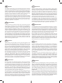
DESCRIPTION
1. Spindle lock
2. Bevel adjustment lever
3. Edge guide lock screw
4. Base plate
5. Edge guide
6. Lower guard
7. Blade
8. Lower guard lever
9. Upper guard
10. Outer blade fl ange
11. Hex-head bolt
12. Wrench
13. Washer
14. Inner blade fl ange
15. Depth adjustment lever
16. Depth of cut
17. Depth pointer
18. Depth scale
19. Bevel scale
20. Bevel pointer
21. Lock-off trigger
22. Switch
23. Live tool indicator
24. Vacuum adapter
25. 0˚ bevel notch
26. 45° bevel notch
SPECIAL SAFETY RULES
Do not use any abrasive wheels.
DANGER
Keep hands away from cutting area. Keep hands
away from blade. Keep your second hand on
auxiliary handle, or motor housing. If both hands are
holding the saw, they cannot be cut by the blade.
Do not reach underneath the workpiece. The
guard cannot protect you from the blade below the
workpiece.
Adjust the cutting depth to the thickness of the
workpiece. Less than a full tooth of the blade teeth
should be visible below the workpiece.
Never hold piece being cut in your hands or
across your leg. Secure the workpiece to a stable
platform. It is important to support the work properly
to minimize body exposure, blade binding, or loss of
control.
Hold power tool by insulated gripping surfaces
only, when performing an operation where the
cutting accessory may contact hidden wiring or its
own cord. Contact with a “live" wire will also make
exposed metal parts of the power tool “live" and shock
the operator.
When ripping always use a rip fence or straight
edge guide. This improves the accuracy of cut and
reduces the chance of blade binding.
Always use blades with correct size and shape
(diamond versus round) of arbour holes. Blades
that do not match the mounting hardware of the saw
will run eccentrically, causing loss of control. Use only
blades specified in this manual, complying with EN
847-1.
Never use damaged or incorrect blade washers
or bolt. The blade washers and bolt were specially
designed for your saw, for optimum performance and
safety of operation.
Causes and operator prevention of kickback:
kickback is a sudden reaction to a pinched, bound
or misaligned saw blade, causing an uncontrolled
saw to lift up and out of the workpiece toward the
operator;
when the blade is pinched or bound tightly by the
kerf closing down, the blade stalls and the motor
reaction drives the unit rapidly back toward the
operator;
if the blade becomes twisted or misaligned in the
cut, the teeth at the back edge of the blade can dig
into the top surface of the wood causing the blade
to climb out of the kerf and jump back toward the
operator.
Kickback is the result of saw misuse and/or incorrect
operating procedures or conditions and can be avoided by
taking proper precautions as given below.
Maintain a firm grip with both hands on the saw
and position your arms to resist kickback forces.
Position your body to either side of the blade, but
not in line with the blade. Kickback could cause the
saw to jump backwards, but kickback forces can be
controlled by the operator, if proper precautions are
taken.
When blade is binding, or when interrupting a cut
for any reason, release the trigger and hold the saw
motionless in the material until the blade comes
to a complete stop. Never attempt to remove the
saw from the work or pull the saw backward while
the blade is in motion or kickback may occur.
Investigate and take corrective actions to eliminate the
cause of blade binding.
When restarting a saw in the workpiece, centre
the saw blade in the kerf and check that saw teeth
are not engaged into the material. If saw blade is
binding, it may walk up or kickback from the workpiece
as the saw is restarted.

2
English
EN
FR DE ES IT NL PT DA SV FI NO RU PL CS HU RO LV LT ET HR SL SK EL TR
Support large panels to minimise the risk of blade
pinching and kickback. Large panels tend to sag
under their own weight. Supports must be placed
under the panel on both sides, near the line of cut and
near the edge of the panel.
Do not use dull or damaged blades. Unsharpened
or improperly set blades produce narrow kerf causing
excessive friction, blade binding and kickback.
Blade depth and bevel adjusting locking levers
must be tight and secure before making cut. If
blade adjustment shifts while cutting, it may cause
binding and kickback.
Use extra caution when making a "plunge cut" into
existing walls or other blind areas. The protruding
blade may cut objects that can cause kickback.
SAFETY INSTRUCTIONS FOR SAWS WITH LOWER
GUARD
Check lower guard for proper closing before each
use. Do not operate the saw if lower guard does
not move freely and close instantly. Never clamp
or tie the lower guard into the open position. If saw
is accidentally dropped, lower guard may be bent.
Raise the lower guard with the retracting handle and
make sure it moves freely and does not touch the
blade or any other part, in all angles and depths of cut.
Check the operation of the lower guard spring.
If the guard and the spring are not operating
properly, they must be serviced before use. Lower
guard may operate sluggishly due to damaged parts,
gummy deposits, or a build-up of debris.
Lower guard should be retracted manually only
for special cuts such as “plunge cuts" and “
compound cuts". Raise lower guard by retracting
handle and as soon as blade enters the material,
the lower guard must be released. For all other
sawing, the lower guard should operate automatically.
Always observe that the lower guard is covering
the blade before placing saw down on bench or
floor. An unprotected, coasting blade will cause the
saw to walk backwards, cutting whatever is in its path.
Be aware of the time it takes for the blade to stop after
switch is released.
SPECIFICATIONS
Voltage 230 V - 240 V 50 Hz
Input 1150 W
No-load speed 5600 RPM
Bore size 20 mm
Blade size 170 mm
Blade
Thickness 1.5 mm
Teeth 12 T
Width of cut 2.2 mm
Cutting capacity
at 0º 55 mm
at 45º 38 mm
Bevel scale 0 - 45º
STANDARD ACCESSORIES
Saw blade
Parallel fence
Wrench
ASSEMBLY
Be sure to disconnect the tool from the power supply
before attaching or removing the saw blade. Be sure that
the teeth of the saw blade are pointing upward at the front
of the tool
INTENDED USE
Sawing wood.
Don’t use it for a purpose not intended.
OPERATION
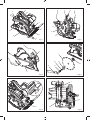
ATTACHING THE BLADE
See Figure 2-4.
1. Press and hold the spindle lock button.
2. Turn the hex-head bolt with a wrench until the spindle
locks.
3. Loosen the hex-head bolt by turning the wrench
anticlockwise.
4. Remove the hex-head bolt and the outer blade washer.
5. Retract the lower guard back with the lower guard
lever as far as possible under the upper guard.
6. Attach the saw blade against the inner blade washer
on the spindle.
7. Fit the outer blade washer and the hex-head bolt.
8. Tighten the hex-head bolt by turning the wrench
clockwise.
9. After tightening the hex-head bolt, release the spindle
lock button.
NOTE: When the blade has been installed, make sure
the spindle lock has been released by spinning the blade
freely.

3
English
EN
FR DE ES IT NL PT DA SV FI NO RU PL CS HU RO LV LT ET HR SL SK EL TR
REMOVING THE BLADE
1. Press and hold the spindle lock button.
2. Turn the hex-head bolt with a wrench until the spindle
locks.
3. Loosen the hex-head bolt by turning the wrench
anticlockwise.
4. Remove the hex-head bolt and the outer blade washer.
5. Retract the lower guard back as far as possible under
the upper guard.
6. Remove the saw blade.
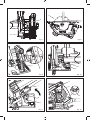
ADJUSTING THE DEPTH OF CUT
See Figure 5-9.
1. Loosen the depth adjustment knob.
2. Slide the base plate to the desired depth using the
depth adjustment knob and then retighten securely.
NOTE: The depth of cut can be determined by the depth
scale or by measuring the distance by which the blade
protrudes from the base plate.
ADJUSTING THE ANGLE
See Figure 10-11.
1. Set the cutting angle to any position between 0° and
45°.
2. Loosen the bevel adjustment knob at the front of the
tool and move the base plate to the desired angle
using the bevel scale.
3. Retighten the bevel adjustment knob.
SWITCH
See Figure 12.
This tool is started and stopped by squeezing and
releasing the trigger switch. To prevent the tool from being
started accidentally, the trigger can only be operated if the
safety button is depressed fi rst. The safety button can be
depressed with the thumb leaving the other fi ngers free to
squeeze the trigger switch. It is not necessary to maintain
pressure on the safety button once the trigger switch has
been depressed.
OPERATION
DANGER
Keep hands away from the cutting area when operating
the tool. Keep the cord away from the cutting area and
position it so that it will not get caught on the workpiece
during the cutting operation.
When cutting, use steady and even pressure in order to
obtain a uniform cut; do not force. Cut at a speed suited to
the workpiece. Cut slowly if the workpiece is hard. Inspect
the saw blade frequently and replace or sharpen it if dull,
to avoid overloading the motor.
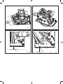
CUTTING POSITION
See Figure 15-16.
When cutting a workpiece at 0°, use point "A" of the base
plate line guide and move the saw along the pencilled
line you have drawn. When cutting at 45°, use point "B".
This line guide shows an approximate line of cut. Make a
sample cut in scrap lumber to determine the actual line
of cut.
CAUTION
When ripping, the rip fence should only touch the workpiece
slightly. Do not force.
LIVE TOOL INDICATOR
This tool features a live tool indicator which illuminates as
soon as the tool is connected to the supply. This warns the
user that the tool is connected and will operate when the
switch is pressed.
MAINTENANCE
After use, check the tool to make sure that it is in top
condition.
It is recommended that you take this tool to a Ryobi
Authorized Service Center for a thorough cleaning and
lubrication at least once a year.
Do not make any adjustments while the motor is running.
Always disconnect the power cord from the socket
before changing removable or expendable parts
before lubricating or working on the unit. Keep handles
dry, clean and free from oil and grease.
If the power supply cord is damaged, it must be replaced
only by the manufacturer or by an authorized service
center to avoid risk. Contact authorized service center.
WARNING
For greater safety and reliability, all repairs should be
performed by an authorised Ryobi Service Centre.
ENVIRONMENTAL PROTECTION
Recycle raw materials instead of disposing
of as waste. The machine, accessories
and packaging should be sorted for
environmental-friendly recycling.

4
English
EN
FR DE ES IT NL PT DA SV FI NO RU PL CS HU RO LV LT ET HR SL SK EL TR
SYMBOLS
Safety Alert
V Volts
Hz Hertz
Alternating Current
W Watts
nₒ No-load speed
min־¹ Revolutions or reciprocations per minute
CE Conformity
GOST-R conformity
Class II, double insulated
Please read the instructions carefully
before starting the machine.
Wear eye protection
Wear ear protection
Wood
Do not cut metals
Width of cut
Ø Diameter
Waste electrical products should not be
disposed of with household waste. Please
recycle where facilities exist. Check with
your local authority or retailer for recycling
advice.
Page is loading ...

6
Français
FR
DE ES IT NL PT DA SV FI NO RU PL CS HU RO LV LT ET HR SL SK EL TREN
la coupe pour une raison quelconque, relâchez
la gâchette et maintenez la scie dans la
pièce à usiner jusqu'à ce que la lame s'arrête
complètement de tourner. Ne tentez jamais de
retirer la scie de la pièce à usiner ou de tirer la scie
vers l'arrière tant que la lame est en rotation:cela
risquerait d'entraîner un rebond. Si la lame se
coince, cherchez-en la cause et prenez les mesures
nécessaires pour que cela ne se reproduise plus.
Avant de faire redémarrer la scie pour reprendre
une coupe, alignez correctement la lame avec le
trait de scie et vérifiez que les dents ne touchent
pas la pièce à usiner. Si la lame est coincée dans la
pièce à usiner, un rebond risque de se produire lors de
la mise en marche de la scie.
Veillez à soutenir les longues pièces à usiner afin
d'éviter que la lame se coince et limiter ainsi les
risques de rebonds. Les longues pièces à usiner
ont tendance à ployer sous leur propre poids. Vous
pouvez placer des supports des deux côtés de la
pièce à usiner, près de la ligne de coupe et au niveau
de l'extrémité de la pièce.
N'utilisez pas de lames émoussées ou
endommagées. Des lames non aiguisées ou mal
montées produiront un trait de scie fin entraînant une
friction excessive de la lame et donc de plus grands
risques de torsion et de rebond.
Avant de commencer une coupe, vérifiez que
les boutons de réglage de la profondeur et de
l'inclinaison sont correctement bloqués. Si les
réglages de la position de la lame se modifient en
cours de coupe, la lame risque de se coincer et un
rebond peut se produire.
Soyez particulièrement prudent lorsque vous
effectuez des coupes en plongée dans des murs
ou autres surfaces aveugles. La lame pourrait
heurter des éléments cachés, ce qui entraînerait un
rebond.
CONSIGNES DE SÉCURITÉ CONCERNANT LE PRO-
TÈGE-LAME
Avant chaque utilisation, vérifiez que le protège-
lame inférieur recouvre correctement la lame.
N'utilisez pas votre scie si le protège-lame
inférieur ne peut pas être actionné librement et
s'il ne se rabat pas instantanément sur la lame.
Ne fixez ou n'attachez jamais le protège-lame
inférieur en position ouverte. Si la scie tombait de
façon accidentelle, le protège-lame inférieur pourrait
se plier. Relevez le protège-lame inférieur à l'aide de
la manette et assurez-vous qu'il peut être manipulé
sans difficulté et qu'il ne touche ni la lame ni aucune
autre pièce quels que soient l'angle et la profondeur
de coupe choisis.
Assurez-vous que le ressort du protège-
lame inférieur est en bon état et fonctionne
correctement. Si le protège-lame ou le ressort
ne fonctionnent pas correctement, faites-les
réparer ou remplacer avant d'utiliser votre scie. Le
mouvement du protège-lame inférieur peut être freiné
par des pièces endommagées, un dépôt de résine ou
une accumulation de sciures.
Le protège-lame ne doit être actionné
manuellement que pour les coupes particulières
telles que les coupes en plongée ou les coupes
doubles. Levez le protège-lame inférieur à l'aide de
la manette.Puis, dès que la lame pénètre dans la
pièce à usiner, relâchez le protège-lame inférieur.
Pour tous les autres types de coupe, le protège-lame
inférieur se met en place automatiquement.
Vérifiez toujours que le protège-lame inférieur
recouvre bien la lame avant de poser votre scie
sur un établi ou sur le sol. Si la lame n'est pas
correctement recouverte, elle peut tourner par inertie
et couper ce qui se trouve sur sa trajectoire. Soyez
conscient du fait que la lame continue de tourner
pendant un certain temps après l'arrêt du moteur.
CARACTÉRISTIQUES
Tension 230 V - 240 V 50 Hz
Alimentation 1150 W
Vitesse à vide 5600 RPM
Alésage 20 mm
Lame 170 mm
Epaisseur 1.5 mm
Dents 12 T
Largeur de coupe 2.2 mm
Capacité de coupe
0° 55 mm
45° 38 mm
Echelle d'inclinaison 0 – 45°
ACCESSOIRES STANDARD
Lame de scie
Guide parallèle
Clé de service
MONTAGE
Assurez-vous de débrancher l'outil du secteur avant de
monter ou de démonter la lame de scie. Assurez-vous
Page is loading ...

8
Français
FR
DE ES IT NL PT DA SV FI NO RU PL CS HU RO LV LT ET HR SL SK EL TREN
TÉMOIN DE MISE SOUS TENSION
Cet outil est équipé d'un témoin d'alimentation qui s'allume
lorsque l'outil est branché sur le secteur. Ceci attire votre
attention sur le fait que l'outil est sous tension et qu’il se
mettra en marche si vous en enfoncez l'interrupteur.
ENTRETIEN
Après utilisation, assurez-vous que votre outil est en bon
état de marche.
Nous vous recommandons d'apporter votre outil au moins
une fois par an dans un Centre Service Agréé Ryobi pour
une lubrifi cation et un nettoyage complets.
N'effectuez aucun réglage lorsque le moteur est en
marche.
Débranchez toujours le câble d'alimentation de la prise
avant de changer des accessoires ou des extensions,
de lubrifi er l'appareil ou d'intervenir dessus. Gardez les
poignées propres, sèches, et exemptes d'huile et de
graisse.
Si le câble d'alimentation est endommagé, il ne doit être
remplacé que par le fabricant ou par un service après-
vente agréé, pour éviter tout danger. Contactez un service
après-vente agréé.
AVERTISSEMENT
Pour plus de sécurité et de fiabilité, toutes les réparations
doivent être effectuées par un Centre Service Agréé Ryobi.
PROTECTION DE L’ENVIRONNEMENT
Recyclez les matières premières au lieu
de les jeter aux ordures ménagères.
Pour protéger l’environnement, l’outil, les
accessoires et les emballages doivent être
triés.
SYMBOLE
Alerte de Sécurité
V Volts
Hz Hertz
Courant alternatif
W Watts
n
o Vitesse à vide
min
-
1
Nombre de tours ou de mouvements par
minute
Conformité CE
Conformité GOST-R
Classe II, isolation double
Veuillez lire attentivement le mode
d’emploi avant de démarrer la machine.
Portez une protection oculaire
Portez une protection auditive
Bois
Ne coupez pas de métal
Largeur de coupe
Ø Diamètre
Les produits électriques hors d’usage
ne doivent pas être jetés avec les
ordures ménagères. Recyclez-les par
l’intermédiaire des structures disponibles.
Contactez les autorité locales pour
vous renseigner sur les conditions de
recyclage.
Page is loading ...
Page is loading ...
Page is loading ...
Page is loading ...

13
Español
ES
IT NL PT DA SV FI NO RU PL CS HU RO LV LT ET HR SL SK EL TRFR DEEN
DESCRIPCIÓN
1. Botón de bloqueo del árbol
2. Botón para regular la inclinación
3. Tornillo de apriete de la guía de corte paralelo
4. Base
5. Guía de corte paralelo
6. Protector de hoja inferior
7. Hoja
8. Palanca del protector inferior de la hoja
9. Protector superior de la hoja
10. Reborde externo
11. Tornillo de la hoja
12. Llave de servicio
13. Junta
14. Reborde interior
15. Pie de regulación de la profundidad de corte
16. Profundidad de corte
17. Indicador de profundidad
18. Escala de profundidad
19. Escala de inclinación
20. Indicador de inclinación
21. Botón para liberar el gatillo
22. Interruptor
23. Indicador de puesta en tensión
24. Adaptador de vacío
25. muesca de bisel de 0˚
26. muesca de bisel de 45°
NORMAS ESPECIALES DE SEGURIDAD
No utilice discos abrasivos.
INSTRUCCIONES DE SEGURIDAD IMPORTANTES
PARA TODOS LOS TIPOS DE SIERRA
PELIGRO
Mantenga las manos fuera de la zona de corte.
Mantenga las manos alejadas de la hoja. La mano
que no sujeta la empuñadura principal de la
máquina debe sostener la empuñadura auxiliar o
bien estar apoyada en el cárter del motor. De este
modo, sus manos no estarán en la zona de corte, en la
trayectoria de la hoja.
No pase las manos por debajo de la pieza
trabajada. el protector de hoja no le protege ya que
no recubre la hoja por debajo de la pieza.
Ajuste la profundidad de corte en función del
grosor de la pieza trabajada. Los dientes de la hoja
no deben sobresalir completamente por debajo de la
pieza trabajada durante el corte.
No sujete NUNCA la pieza trabajada con la mano
o entre las piernas. Fíjela en un soporte estable.
Es fundamental fijar correctamente la pieza trabajada
para evitar el riesgo de heridas y no doblar la hoja o
perder el control de la máquina.
Sujete la máquina por sus partes aisladas y
antideslizantes cuando trabaje en una superficie
debajo de la cual puedan pasar cables eléctricos o
cuando el trabajo que desee realizar puede hacer
que el cable de alimentación esté en la trayectoria
de la máquina. Si la máquina se pusiera en contacto
con los cables eléctricos en tensión, la corriente
pasaría por las partes metálicas y usted podría recibir
una descarga eléctrica.
Utilice siempre una guía de corte paralela o un
listón recto cuando efectúe un corte paralelo.
Obtendrá una mayor precisión de corte y evitará
doblar la hoja.
Utilice hojas de tamaño y forma adecuados al
diámetro interior del árbol. Unas hojas que no se
adaptan al árbol en el que se deben montar no girarán
correctamente y provocarán una pérdida de control.
Use solamente hojas especificadas en este manual,
según EN 847-1.
No utilice tornillos ni discos de sujeción de las
hojas defectuosos o inadaptados. Los tornillos y los
discos de sujeción de las hojas han sido especialmente
diseñados para este modelo de sierra, para obtener
los mejores resultados y una óptima seguridad.
INSTRUCCIONES DE SEGURIDAD ADICIONALES
PARA TODOS LOS TIPOS DE SIERRA
Causas de los rebotes y prevención:
El rebote es una reacción repentina que se produce
cuando la hoja se atasca, se dobla o si está mal
alineada; la sierra se libera repentinamente de la
pieza trabajada y retrocede de forma violenta en
dirección al usuario.
Cuando la hoja se atasca en la madera, se para y
el motor, que sigue girando, expulsa la sierra en el
sentido opuesto al sentido de rotación de la hoja,
es decir, hacia al usuario.
Si la hoja se dobla o está mal alineada, los dientes
situados en la parte trasera de la hoja pueden
hundirse en la superficie de la madera, expulsando
bruscamente la hoja de la pieza trabajada hacia el
usuario.
Por lo tanto, el rebote es el resultado de una mala utilización
de la máquina y/o de procedimientos o condiciones de
corte incorrectas.Puede evitarse cumpliendo con algunas
precauciones.
Sujete firmemente la sierra con ambas manos
y coloque sus brazos de tal modo que puedan
controlar un posible rebote. Al trabajar, póngase a

14
Español
ES
IT NL PT DA SV FI NO RU PL CS HU RO LV LT ET HR SL SK EL TRFR DEEN
un lado de la sierra, no se ponga nunca en la línea
de la hoja. El rebote expulsa repentinamente la sierra
hacia atrás, pero este movimiento puede controlarse
si el usuario se lo espera y está preparado para ello.
Si la hoja se atasca o si debe interrumpir el corte
por cualquier motivo, suelte el gatillo y mantenga
la sierra en la pieza trabajada hasta que la hoja deje
de girar completamente. No intente retirar la sierra
de la pieza trabajada o tirar de ella hacia atrás
mientras la hoja esté girando:podría provocar un
rebote. Si la hoja se atasca, averigüe cuál es la causa
y tome las medidas necesarias para que no se repita.
Antes de volver a poner en marcha la sierra para
reanudar un corte, alinee correctamente la hoja
con el paso de la sierra y compruebe que los
dientes no tocan la pieza trabajada. Si la hoja queda
atascada en la pieza trabajada, puede producirse un
rebote al poner en marcha la sierra.
Soporte los paneles grandes para minimizar el
riesgo de pellizcos de la hoja y rebote. Los paneles
grandes tienden a hundirse bajo su propio peso. Se
deben colocar soportes bajo el panel a ambos lados,
cerca de la línea de corte y cerca del borde del panel.
No utilice hojas de sierra desafiladas o
deterioradas. Una hoja desafilada o mal montada
producirá un corte de sierra fino, lo cual provocará
una fricción excesiva de la hoja y, por tanto, mayores
riesgos de torsión y rebote.
Antes de iniciar un corte, compruebe que los
botones de ajuste de la profundidad y de la
inclinación están correctamente bloqueados.
Si los ajustes de la posición de la hoja se modifican
durante el corte, la hoja puede atascarse y provocar
un rebote.
Tenga mucho cuidado cuando realice cortes en
el centro de la pieza trabajada en paredes u otras
superficies ciegas. La hoja podría chocar contra
elementos ocultos, lo que produciría un rebote.
INSTRUCCIONES DE SEGURIDAD RELATIVAS AL
PROTECTOR DE HOJA
Antes de cada utilización, compruebe que el
protector inferior de la hoja recubre correctamente
la hoja. No utilice la sierra si el protector inferior
de la hoja no se puede accionar libremente y si
no se cierra instantáneamente contra la hoja. No
fije ni sujete el protector inferior de la hoja en
posición abierta. Si la sierra se cae accidentalmente,
el protector de hoja inferior puede doblarse. Levante el
protector de hoja inferior con la manecilla y compruebe
que puede manipularlo fácilmente y que no toca la
hoja ni ninguna otra pieza, independientemente del
ángulo y de la profundidad de corte seleccionados.
Compruebe que el resorte del protector inferior
de la hoja está en buen estado y funciona
correctamente. Si el protector de hoja o el resorte
no funcionan correctamente, hágalos reparar o
reemplazar antes de volver a utilizar la sierra.
El movimiento del protector de hoja inferior puede
resultar frenado por alguna pieza dañada, una
acumulación de resina o serrín.
El protector de hoja sólo se colocará manualmente
para los cortes especiales como los cortes en el
centro de la pieza trabajada o los cortes dobles.
Levante el protector inferior de la hoja con la
manecilla correspondiente.En cuanto la hoja
penetra en la pieza, suelte el protector inferior de la
hoja. Para todos los demás tipos de cortes, el protector
inferior de la hoja se coloca automáticamente.
Cerciórese de que el protector inferior de la hoja
cubra completamente la hoja antes de dejar la
sierra en un banco de trabajo o en el suelo. Si la
hoja no está correctamente cubierta, puede girar por
inercia y cortar lo que se encuentra en su trayectoria.
Tenga presente que la hoja sigue girando durante un
tiempo después de parar el motor.
ESPECIFICACIONES
Tensión 230 V - 240 V 50 Hz
Cargador 1150 W
Velocidad sin carga 5600 RPM
Diámetro interior 20 mm
Diámetro de la hoja 170 mm
Hoja
Grosor 1.5 mm
Dientes 12 T
Anchura de fresado 2.2 mm
Capacidad de corte
0° 55 mm
45° 38 mm
Escala de inclinación 0 – 45°
ACCESORIOS ESTÁNDARES
Cuchilla de la sierra
Guía paralela
Llave de servicio
Page is loading ...

16
Español
ES
IT NL PT DA SV FI NO RU PL CS HU RO LV LT ET HR SL SK EL TRFR DEEN
de madera para establecer la verdadera línea de corte.
PRECAUCIÓN
Cuando utilice una guía paralela, la misma sólo debe tocar
ligeramente el borde de la pieza. No forzar.
INDICADOR DE PUESTA EN TENSIÓN
Esta herramienta cuenta con un indicador de presencia
de tensión eléctrica que se enciende cuando la
herramienta está enchufada. Esto avisa al usuario de
que la herramienta está conectada y de que se pondrá en
marcha en cuanto pulse el interruptor.
MANTENIMIENTO
Después de utilizar la máquina, cerciórese de que se
encuentre en perfecto estado de marcha.
Le recomen-damos que lleve la máquina al menos una
vez al año a un Centro de Servicio Habilitado Ryobi para
una lubricación y una limpieza completas.
No haga ningún ajuste cuando el motor esté en marcha.
Desenchufar siempre la herramienta antes de cambiar
cualquier pieza amovible o fungible, antes de lubricarla o
antes de trabajar en la unidad. Mantenga las asas secas,
limpias y libres de aceite y grasa.
Si el cable de alimentación está dañado, debería ser
reemplazado únicamente por el fabricante o por un centro de
servicio autorizado para evitar riesgos. Contacto Centro de
Servicio Autorizado
ADVERTENCIA
Para más seguridad y fiabilidad, todas las reparaciones
deben ser efectuadas por un Centro de Servicio Habilitado
Ryobi.
PROTECCIÓN DEL MEDIO AMBIENTE
Recicle las materias primas en lugar
de tirarlas a la basura doméstica. Para
proteger el medio ambiente, debe separar
la herramienta, los accesorios y los
embalajes.
SÍMBOLO
Alerta de seguridad
V Voltios
Hz Hertzios
Corriente alterna
W Vatios
n
o Velocidad sin carga
min
-
1
Número de revoluciones o movimientos
por minuto
Conformidad con GOST-R
Conformidad con CE
Clase II, doble aislamiento
Por favor lea las instrucciones
detenidamente antes de arrancar la
máquina.
Utilice gafas de seguridad
Utilice dispositivos de protección para
los oídos
Madera
No corte metales
Anchura de fresado
Ø Diámetro
Los productos eléctricos de desperdicio
no deben desecharse con desperdicios
caseros. Por favor recíclelos donde
existan dichas instalaciones.
Compruebe con su autoridad local o
minorista para reciclar.

17
Italiano
IT
NL PT DA SV FI NO RU PL CS HU RO LV LT ET HR SL SK EL TRFR DE ESEN
DESCRIZIONE
1. Pulsante di bloccaggio dell’albero
2. Pulsante di regolazione dell’inclinazione
3. Vite di serraggio della guida di taglio parallela
4. Base
5. Guida di taglio parallela
6. Paralama inferiore
7. Lama
8. Leva del paralama inferiore
9. Paralama superiore
10. Flangia esterna
11. Vite della lama
12. Chiave di servizio
13. Rondella
14. Flangia interna
15. Staffa di regolazione della profondità di taglio
16. Profondità di taglio
17. Puntatore di profondità
18. Scala di profondità
19. Scala di inclinazione
20. Puntatore di inclinazione
21. Dispositivo di sblocco del grilletto
22. Interruttore
23. Spia luminosa di presenza tensione
24. Vuoto adattatore
25. tacca smussatura 0˚
26. tacca smussatura 45°
NORME SPECIALI DI SICUREZZA
Non utilizzare mai dischi abrasivi.
NORME DI SICUREZZA IMPORTANTI PER TUTTI I TIPI
DI SEGHE
PERICOLO
Tenere le mani lontane dall'area di taglio. Tenere
le mani lontane dalla lama. La mano che non tiene
l'impugnatura principale dell'apparecchio deve
tenere l'impugnatura ausiliaria oppure essere
posata sul carter del motore. In questo modo, le mani
non rischieranno di trovarsi nella zona di taglio, sulla
traiettoria della lama.
Non passare le mani sotto il pezzo da lavorare. Per
effettuare un lavoro efficace, è importante controllare
attentamente la pressione esercitata sull'apparecchio
e la superficie di contatto tra la mola ed il pezzo da
lavorare.
Regolare la profondità di taglio in funzione dello
spessore del pezzo da lavorare. Al momento
del taglio, i denti della lama non devono sporgere
interamente sotto il pezzo da lavorare.
Non tenere MAI il pezzo da lavorare con la mano
o tra le gambe. Fissarlo su un supporto stabile.
Si raccomanda di fissare correttamente il pezzo da
lavorare, in modo tale da evitare eventuali rischi di
lesioni, e di non piegare la lama per non perdere il
controllo dell'apparecchio.
Quando si lavora su una superficie che potrebbe
nascondere fili elettrici o se il lavoro da eseguire
può portare il cavo d’alimentazione a trovarsi sulla
traiettoria dell’apparecchio, afferrare quest’ultimo
tenendolo soltanto per le parti isolate ed
antiscivolo. Il contatto con fili sotto tensione potrebbe
trasmettere corrente alle parti in metallo e provocare
scosse elettriche.
Nell'effettuare un taglio parallelo, utilizzare sempre
una guida di taglio parallela o un listello diritto. In
questo modo, sarà possibile migliorare la precisione di
taglio ed evitare di piegare la lama.
Utilizzare sempre lame di dimensioni e forma
idonee all'alesaggio dell'albero. Una lama non
idonea all'albero sul quale deve essere montata non
è in grado di girare correttamente e può causare una
perdita del controllo dell'apparecchio. Utilizzare solo
lame specificate con questo manuale, rispettando lo
standard EN 847-1.
Non utilizzare mai viti né flange di lama difettose o
inadeguate. Le flange e le viti della lama sono state
studiate appositamente per questo modello di sega,
a garanzia di un livello di sicurezza e prestazioni
ottimale.
NORME DI SICUREZZA SUPPLEMENTARI PER TUTTI
I TIPI DI SEGHE
Cause dei contraccolpi e prevenzione:
Il contraccolpo è una reazione improvvisa, che
si verifica quando la lama si incastra, si piega o
è erroneamente allineata; in tali condizioni, la
sega si disinserisce improvvisamente dal pezzo
da lavorare e rimbalza con violenza in direzione
dell'operatore.
Se si incastra nel legno, la lama si blocca e il
motore, che invece continua a girare, scaglia la
sega nella direzione opposta al senso di rotazione
della lama, vale a dire verso l'operatore.
Se la lama si piega o è erroneamente allineata,
i denti situati nella sua parte posteriore rischiano
di penetrare nella superficie del legno, facendo
uscire bruscamente la lama dal pezzo da lavorare,
in direzione dell'operatore.
Il contraccolpo è pertanto il risultato di un utilizzo errato
dell'apparecchio e/o di procedimenti o di condizioni di
taglio inappropriati.Questa evenienza può essere evitata
assicurandosi di adottare alcune misure precauzionali.

18
Italiano
IT
NL PT DA SV FI NO RU PL CS HU RO LV LT ET HR SL SK EL TRFR DE ESEN
Tenere saldamente la sega con entrambe le mani
e posizionare le braccia in modo tale che possano
controllare un eventuale contraccolpo. Durante
l'esecuzione del lavoro, collocarsi su un lato della
sega:non rimanere mai lungo l'asse della lama.
Il contraccolpo fa sì che la sega venga scagliata
improvvisamente all'indietro, ma questo movimento
può essere tenuto sotto controllo se l'operatore lo
prevede e si prepara all'evenienza.
Qualora la lama si incastri o si debba interrompere
il taglio per un motivo qualsiasi, rilasciare il
grilletto e mantenere la sega nel pezzo da lavorare,
sino a quando la lama non cessa completamente
di girare. Non tentare mai di rimuovere la sega dal
pezzo né di tirarla all'indietro finché la lama è in
rotazione:questa manovra potrebbe provocare un
contraccolpo. Se la lama si incastra, individuarne la
causa e adottare le misure necessarie affinché ciò non
si verifichi più.
Prima di riavviare la sega per riprendere
un'operazione di taglio, allineare correttamente
la lama rispetto al taglio ed assicurarsi che i
denti non tocchino il pezzo da lavorare. Se la
lama è incastrata nel pezzo da lavorare, al momento
della messa in funzione della sega può verificarsi un
contraccolpo.
Non dimenticare di sorreggere i pezzi lunghi, onde
evitare che la lama si incastri e limitare pertanto i
rischi di contraccolpo. I pezzi lunghi tendono infatti a
flettersi sotto il loro stesso peso. È possibile sistemare
appositi supporti su entrambi i lati del pezzo, accanto
alla linea di taglio e a livello dell'estremità del pezzo.
Non utilizzare lame smussate o danneggiate. Una
lama non affilata o montata erroneamente genera
un taglio sottile, che dà luogo ad un attrito eccessivo
della lama e pertanto a maggiori rischi di torsione e di
contraccolpo.
Prima di iniziare un'operazione di taglio,
assicurarsi che le manopole di regolazione della
profondità e dell'inclinazione siano adeguatamente
bloccate. Se le regolazioni della posizione della lama
si modificano durante il taglio, la lama rischia infatti di
incastrarsi e può verificarsi un contraccolpo.
Prestare particolare attenzione quando si
effettuano tagli a tuffo su pareti o altre superfici
cieche. La lama potrebbe urtare elementi nascosti,
con conseguente pericolo di contraccolpo.
NORME DI SICUREZZA RELATIVE AL PARALAMA
Prima di ogni utilizzo, verificare che il paralama
inferiore copra correttamente la lama. Non
utilizzare la sega circolare se il paralama inferiore
non può essere azionato liberamente e se non si
ripiega istantaneamente sulla lama. Non fissare
né bloccare mai il paralama inferiore in posizione
aperta. Se la sega cade accidentalmente, il paralama
inferiore potrebbe piegarsi. Sollevare il paralama
inferiore servendosi dell'apposita leva ed assicurarsi
che possa essere maneggiato senza difficoltà e
che non tocchi né la lama né altri componenti,
indipendentemente dall'angolo e dalla profondità di
taglio prescelti.
Assicurarsi che la molla del paralama inferiore
sia in buono stato e funzioni correttamente. Se il
paralama o la molla non funzionano correttamente,
farli riparare o sostituire prima di utilizzare la sega.
Il movimento del paralama inferiore può essere frenato
da componenti danneggiati, da un deposito di resina o
da un accumulo di segatura.
Il paralama non deve essere azionato
manualmente, se non per i tagli particolari quali i
tagli a tuffo o i tagli doppi. Sollevare il paralama
inferiore mediante l'apposita leva. Non appena
la lama entra nel pezzo da lavorare, rilasciare il
paralama inferiore. Per tutti gli altri tipi di taglio il
paralama inferiore si posiziona automaticamente.
Prima di posare la sega su un banco da lavoro o
sul pavimento, assicurarsi sempre che il paralama
inferiore copra adeguatamente la lama. Se la lama
non è coperta correttamente, può ruotare per inerzia
e tagliare ciò che si trova sulla propria traiettoria. Non
dimenticare mai che la lama continua a girare ancora
per qualche tempo dopo l'arresto del motore.
SPECIFICHE
Voltaggio 230 V - 240 V 50 Hz
Alimentazione 1150 W
Velocità a vuoto 5600 RPM
Alesaggio 20 mm
Diametro della lama 170 mm
Lama
Spessore 1.5 mm
Denti 12 T
Larghezza di fresatura 2.2 mm
Capacità di taglio
0° 55 mm
45° 38 mm
Scala di inclinazione 0 – 45°

19
Italiano
IT
NL PT DA SV FI NO RU PL CS HU RO LV LT ET HR SL SK EL TRFR DE ESEN
ACCESSORI STANDARD
Lama sega
Guida parallela
Chiave di servizio
MONTAGGIO
Assicurarsi di aver scollegato l'utensile dall'alimentazione
prima di collegarlo o prima di rimuovere la lama.
Assicurarsi che i denti della lama siano rivolti in alto dalla
parte anteriore dell'utensile.
UTILIZZO
Taglio del legno.
Non utilizzare per lavori per scopi non previsti nelle istruzioni.
FUNZIONAMENTO
INSTALLAZIONE
Vedere la fi gura 2-4.
1. Premere e tenere premuto il tasto dell'albero.
2. Girare il bullone esagonale con una chiave fi no a che
l'albero non si blocchi.
3. Allentare il bullone esagonale girando la chiave in
senso anti-orario.
4. Togliere la vite della lama ed il disco esterno della
lama.
5. Sollevare completamente il paralama inferiore
mediante l’apposita leva posta sotto il paralama
superiore.
6. Montare la lama della motosega contro la rondella
della lama interna sull'albero.
7. Installare la rondella della lama esterna e il bullone
esagonale.
8. Serrare il bullone esagonale girando la chiave in
senso orario.
9. Dopo aver serrato la vite, rilasciare il pulsante di
bloccaggio dell’albero.
NOTE: Quando la lama è stata installata, assicurarsi che
il bloccaggio del mandrino è stata rilasciata facendo girare
la lama liberamente.
ESTRAZIONE
1. Premere e tenere premuto il tasto dell'albero.
2. Girare il bullone esagonale con una chiave fi no a che
l'albero non si blocchi.
3. Allentare il bullone esagonale girando la chiave in
senso anti-orario.
4. Togliere la vite della lama ed il disco esterno della
lama.
5. Ritrarre lo schermo inferiore posteriore per quanto
possibile sotto lo schermo superiore.
6. Rimuovere la lama.
REGOLAZIONE DELLA PROFONDITÀ DI TAGLIO
Vedere la fi gura 5-9.
1. Allentare la manopola di regolazione della profondità.
2. Utilizzando la staffa di regolazione della profondità di
taglio, fare scorrere la base alla profondità desiderata
e richiudere con forza il pulsante.
NOTE: Per determinare la profondità di taglio si può
utilizzare la scala di profondità o misurare quanto la lama
fuoriesce dalla base.Le maschere antipolvere permettono
di fi ltrare le particelle generate dall’operazione eseguita.
REGOLAZIONE DELL'ANGOLO
Vedere la fi gura 10-11.
1. Set the cutting angle to any position between 0° and
45°.
2. Allentare il pulsante di regolazione dell’inclinazione,
posto nella parte anteriore dell’apparecchio e,
mediante la scala d’inclinazione, posizionare la base
all’angolazione desiderata.
3. Riassicurare la manopola di regolazione smussatura.
INTERRUTTORE
Vedere la fi gura 12.
Per avviare o arrestare l’apparecchio, premere o rilasciare
il grilletto. Onde evitare avvii involontari dell’apparecchio,
il grilletto funziona solo quando il pulsante di sicurezza è
premuto. Il pulsante di sicurezza può essere premuto con
il pollice, in questo modo è possibile premere il grilletto
con le altre dita. Non è necessario mantenere la pressione
sul tasto di sicurezza una volta rilasciato l'interruttore.
FUNZIONAMENTO
PERICOLO
Tenere le mani lontane dalla zona di taglio mentre
si mette in funzione l'utensile. Tenere il cavo
d’alimentazione lontano dalla zona di taglio e collocarlo
in modo tale che, durante le operazioni di taglio, non
rimanga impigliato nel pezzo da lavorare.
Quando si svolgono operazioni di taglio, fare una
pressione normale ed equilibrata in modo da ottenere
un taglio uniforme; non forzare. Adottare una velocità di
taglio conforme al pezzo da lavorare. Tagliare piano se
il pezzo sul quale si sta lavorando è duro. Controllare
frequentemente la lama e sostituirla o affi larla se
necessario, per evitare di sovraccaricare il motore.
TAGLIARE
Vedere la fi gura 15-16.

20
Italiano
IT
NL PT DA SV FI NO RU PL CS HU RO LV LT ET HR SL SK EL TRFR DE ESEN
Quando si taglia con la lama verticale, utilizzare il punto "
A " della tacca di guida sulla base e seguire con la sega
la linea di guida tracciata con la matita. Quando si effettua
un taglio a 45°, utilizzare il punto " B ". La tacca di guida
indica all’incirca la linea di taglio. Per determinare la linea
di guida reale, effettuare un taglio di prova in un pezzo di
legno scarto.
ATTENZIONE
Quando si utilizza una guida parallela, fare attenzione che
tocchi solo leggermente il bordo del pezzo da tagliare. Non
esercitare forza.
SPIA LUMINOSA DI PRESENZA TENSIONE
Questo utensile è dotato di una spia luminosa di presenza
tensione, che si illumina quando l’apparecchio è collegato
all’alimentazione elettrica. Questa spia attira l’attenzione
dell’utilizzatore sul fatto che la molatrice è sotto tensione
e si mette in funzione non appena l’interruttore viene
spostato in avanti.
MANUTENZIONE
Dopo ogni utilizzazione, verifi care sempre lo stato
dell’apparecchio.
Si raccomanda di portare l'apparecchio almeno una volta
l'anno presso un Centro di Assistenza Autorizzato Ryobi
per sottoporlo ad una completa lubrifi cazione e pulitura.
Non effettuare alcun tipo di regolazione quando
l’apparecchio è in funzione.
Scollegare sempre la molatrice dall'alimentazione
elettrica prima di sostituire un componente O di lubrifi care
l'apparecchio e comunque prima di effettuare qualsiasi
intervento di manutenzione.
Tenere i manici puliti, asciutti e senza tracce di olio e
grasso.
Se il cavo di alimentazione è danneggiato deve essere
sostituito solo dalla ditta produttrice o dal centro servizi
autorizzato per evitare eventuali rischi. Contattare il centro
servizi autorizzato
AVVERTENZE
Per maggiore sicurezza ed affidabilità, effettuare tutte le
riparazioni presso un Centro di Assistenza Autorizzato
Ryobi.
TUTELA DELL’AMBIENTE
Riciclare le materie prime anziché gettarle
tra i rifi uti domestici. Per tutelare l’ambiente,
l’apparecchio, gli accessori e gli imballaggi
devono essere smaltiti separatamente.
SIMBOLO
Allarme di sicurezza
V Volt
Hz Hertz
Corrente alternata
W Watt
no Velocità a vuoto
min
-
1
Numero di giri o di movimenti al minuto
Conformità GOST-R
Conformità CE
Classe II con doppio isolamento
Leggere attentamente le istruzioni prima di
avviare l’utensile.
Indossare occhiali di protezione
Indossare cuffi e di protezione
Legno
Non tagliare metalli
Larghezza di fresatura
Ø Diametro
I prodotti elettrici non devono essere
smaltiti con i rifi uti domestici. Vi sono
strutture per smaltire tali prodotti.
Informarsi presso il proprio Comune
o rivenditore di sicurezza per smatire
adeguatamente tali rifi uti.

21
Nederlands
NL
PT DA SV FI NO RU PL CS HU RO LV LT ET HR
SL
SK EL TRFR DE ES ITEN
BESCHRIJVING
1. Asvergrendeling
2. Instelknop voor de afschuinhoek
3. Blokkeerschroef van de parallelgeleider
4. Voetplaat
5. Parallelgeleider
6. Onderste beschermkap
7. Zaagblad
8. Hendel van de onderste beschermkap
9. Bovenste beschermkap
10. Buitenste fl ens
11. Zaagbladschroef
12. Speciale sleutel
13. Sluitring
14. Binnenste fl ens
15. Instelbeugel van de zaagdiepte
16. Zaagdiepte
17. Diepte pointer
18. Schaalverdeling
19. Afschuinschaalverdeling
20. Chuine pointer
21. Ontgrendelknop van de aan/uit-drukschakelaar
22. Aan-/uitschakelaar
23. Netspanningsverklikker
24. Vacuüm-adapter
25. 0˚ afschuininkeping
26. 45˚ afschuininkeping
BIJZONDERE VEILIGHEIDSVOORSCHRIFTEN
Monteer nooit een slijpschijf op dit apparaat.
BELANGRIJKE VEILIGHEIDSVOORSCHRIFTEN
VOOR ALLE TYPEN ZAGEN
GEVAAR
Houd uw handen weg van het zaaggebied. Houd uw
handen weg van het zaagblad. De hand waarmee
u niet de hoofdhandgreep vasthoudt moet de
hulphandgreep vasthouden of op de motorombouw
rusten. Op die manier loopt u niet het gevaar dat uw
handen in zaagzone in het zaagblad komen.
Ga niet met uw handen langs de onderkant van
het werkstuk. hier bestaat groot gevaar omdat de
beschermkap hier niet het zaagblad bedekt.
Stel de zaagdiepte af al naar gelang de dikte van
het werkstuk. De tanden van het zaagblad mogen
niet helemaal onder het werkstuk uitkomen tijdens het
zagen.
Houd het werkstuk NOOIT met uw hand of tussen
uw benen vast. Maak het werkstuk vast op een
stabiele ondergrond. Het is uiterst belangrijk om het
werkstuk goed vast te maken om lichamelijk letsel
te voorkomen en om het zaagblad niet te verbuigen
waardoor u de macht over het apparaat zou kunnen
verliezen.
Houd het apparaat alleen vast aan geïsoleerde en
slipvrije delen als u in een oppervlak of ondergrond
werkt waarin zich eventueel elektrische leidingen
bevinden of als bij het uitvoeren van de
werkzaamheden het netsnoer in de buurt van het
werktuig zou kunnen komen. Door aanraking met
onder stroom staande draden kunnen de metalen
delen stroom gaan voeren en een elektrische schok
veroorzaken.
Gebruik altijd een parallelgeleider of een rechte lat
bij het schulpen. Zo werkt u veel nauwkeuriger en
voorkomt u dat het zaagblad wordt verbogen.
Gebruik altijd zaagbladen waarvan de grootte en
de vorm geschikt zijn voor de dikte van de as.
Zaagbladen die niet geschikt zijn voor de as waarop
ze moeten worden gemonteerd zullen niet op de
juiste manier ronddraaien en kunnen u de macht
over het apparaat doen verliezen. Gebruik uitsluitend
zaagbladen die in deze gebruiksaanwijzing worden
gespecificeerd en die overeenstemmen met EN 847-1.
Gebruik nooit schroeven of flenzen afkomstig van
defecte of verkeerde zaagbladen. De flenzen en
de zaagbladschroeven zijn speciaal bedoeld voor uw
type zaagmachine en verschaffen optimale zekerheid
en prestaties.
AANVULLENDE VEILIGHEIDSVOORSCHRIFTEN
VOOR ALLE TYPEN ZAGENAFBRAAMSCHIJF
De oorzaken van terugslagen en het voorkomen
ervan:
Een terugslag is een plotselinge reactie die
optreedt wanneer het zaagblad zich vastklemt of
verbuigt of als het blad verkeerd is uitgelijnd; de
zaagmachine komt plotseling los uit het werkstuk
en slaat met geweld terug in de richting van de
gebruiker.
Wanneer het zaagblad zich in het hout vastklemt,
komt het blad plotseling tot stilstand en de motor,
die door blijft draaien, werpt de zaagmachine in
de tegenovergestelde richting van de draairichting
van het zaagblad, dat wil zeggen naar de gebruiker
toe.
Als het zaagblad verbogen raakt of verkeerd
is uitgelijnd, bestaat het gevaar dat de tanden
die zich aan de andere kant van het zaagblad
bevinden, zich in het houtoppervlak drukken, wat
het zaagblad plotseling uit het werkstuk doen
springen in de richting van de gebruiker.
Page is loading ...

23
Nederlands
NL
PT DA SV FI NO RU PL CS HU RO LV LT ET HR
SL
SK EL TRFR DE ES ITEN
Asgat 20 mm
Diameter van het
zaagblad
170 mm
Zaagblad
Dikte 1.5 mm
Tanden 12 T
Freesbreedte 2.2 mm
Zaagcapaciteit
0° 55 mm
45° 38 mm
Afschuinschaalverdeling 0 – 45°
STANDAARD ACCESSOIRES
Zaagblad
Zijgeleider
Speciale sleutel
MONTAGE
Zorg ervoor dat het werktuig van de stroomvoorziening
wordt ontkoppeld voor u het zaagblad vastmaakt of
verwijdert. Zorg ervoor dat de tanden van het zaagblad
naar boven wijzen aan de voorkant van het werktuig.
BEOOGD GEBRUIK
Zagen van hout.
Gebruik het gereedschap alleen waarvoor het werd
ontworpen.
BEDIENING
INZETTEN
Zie afbeelding 2-4.
1. Druk en houd de spindelvergrendelknop ingedrukt.
2. Draai de inbuskopbout met een sleutel tot de spindel
vergrendelt.
3. Maak de inbuskopbout los door de sleutel tegen de richting
van de wijzers van de klok te draaien.
4. Verwijder de zaagbladschroef en de buitenfl ens.
5. Klap de onderste beschermkap helemaal omhoog met
behulp van de bijbehorende hendel onder de bovenste
beschermkap.
6. Maak het zaagblad tegen de binnenste zaagbladsluitring op
de as vast.
7. Bevestig de buitenste zaagbladsluitring en de inbuskopmoer.
8. Span de inbuskopbout aan door de sleutel met de richting
van de wijzers van de klok te draaien.
9. Nadat u de zaagbladschroef hebt vastgezet, kunt u de
asvergrendeling loslaten.
OPMERKING: Als het blad is geïnstalleerd, controleert u of de
spilvergrendeling vrij is vrijgegeven door het draaien van het
blad.
VERWIJDEREN
1. Druk en houd de spindelvergrendelknop ingedrukt.
2. Draai de inbuskopbout met een sleutel tot de spindel
vergrendelt.
3. Maak de inbuskopbout los door de sleutel tegen de richting
van de wijzers van de klok te draaien.
4. Verwijder de zaagbladschroef en de buitenfl ens.
5. Trek de onderste beschermer zo ver mogelijk terug onder de
bovenste beschermer.
6. Verwijder het zaagblad.
DIEPTE VAN DE ZAAGSNEDE AANPASSEN
Zie afbeelding 5-9.
1. Maak de diepteafstellingsknop los.
2. Verschuif de voetplaat met behulp van de instelbeugel tot
de gewenste zaagdiepte en draai daarna de blokkeerknop
stevig aan.
OPMERKING: De zaagdiepte kan worden bepaald door afl ezing
op de diepteschaalverdeling of door op te meten hoeveel de het
zaagblad onder de voetplaat uitsteekt.
HOEK AFSTELLEN
Zie afbeelding 10-11.
1. Stel de zaaghoek af op een positie tussen 0° en 45°.
2. Zet de instelknop voor de afschuinhoek voorop de machine
los et plaats de voetplaat onder de gewenste afschuinhoek
met behulp van de afschuinschaalverdeling.
3. Span de afschuinafstelknop opnieuw aan.
AAN-/UITSCHAKELAAR
Zie afbeelding 12.
Door indrukken of loslaten van de schakelaar kunt u deze
machine aan- of uitzetten. Om te voorkomen dat de machine
ongewild in werking treedt, werkt de schakelaar alleen als de
ontgrendelknop is ingedrukt. De ontgrendelknop kan worden
ingedrukt met de duim:de schakelaar kan daarom worden
bediend met de andere vingers. Het is niet nodig om de druk op
de veiligheidsknop te houden eens de gashendel werd ingedrukt.
BEDIENING
GEVAAR
Houd handen weg van het zaagbereik wanneer u de
machine bedient. Houd het netsnoer uit de buurt van
de zaagzone en leg het zo dat het niet kan worden
meegetrokken door het werkstuk tijdens het zagen.

24
Nederlands
NL
PT DA SV FI NO RU PL CS HU RO LV LT ET HR
SL
SK EL TRFR DE ES ITEN
Wanneer u zaagt, pas dan een rustige en evenwichtige druk
toe om een uniforme insnede te bekomen; forceer niet. De
snijsnelheid moet zijn aangepast aan het te zagen materiaal.
Zaag traag als het werkstuk hard is. Controleer het zaagblad
regelmatig en vervang of slijp het indien het bot wordt om te
voorkomen dat de motor wordt overbelast.
ZAAGSNEDE
Zie afbeelding 15-16.
Als u met het zaagblad in de verticale stand zaagt, gebruikt u
het punt "A" van de geleider-inkeping in de voetplaat en volgt
u daarmee de lijn die u met potlood op het werkstuk hebt
afgetekend. Als u zaagt onder een hoek van 45°, gebruikt u punt
"B". Deze geleider-inkeping geeft bij benadering de toekomstige
zaagsnede aan. Neem eerst een proef in een stuk afvalhout om
na te gaan waar de werkelijke zaagsnede komt.
LET OP
Als u met een parallelgeleider werkt, mag u daarmee
de rand van het werkstuk slechts licht raken. Forceer de
machine niet.
NETSPANNINGSVERKLIKKER
Dit werktuig is voorzien van een netspanningsverklikker die
gaat branden van zodra het apparaat op een stopcontact is
aangesloten. Dit waarschuwt de gebruiker dat het werktuig onder
spanning staat en gaat werken zodra u de schakelaar indrukt.
ONDERHOUD
Controleer na elk gebruik of uw machine in goede staat van
werking verkeert.
Aanbevolen wordt om uw machine minstens éénmaal per
jaar door een erkend Ryobi servicecentrum volledig te laten
doorsmeren en schoonmaken.
Probeer niet om een afstelling te wijzigen als de motor draait.
Trek altijd eerst de stekker uit het stopcontact voor u
verwijderbare of vervangbare onderdelen vervangt, het apparaat
smeert of andere werken uitvoert. Houd de handvaten droog,
schoon en vrij van olie en vet.
Als het stroomsnoer beschadigd is, mag deze uitsluitend
worden vervangen door de fabrikant of door een geautoriseerd
onderhoudscentrum om risico te voorkomen. Neem contact op met
een Geautoriseerd Onderhoudscentrum
WAARSCHUWING
Alle reparaties moeten worden uitgevoerd door een Erkend
Ryobi Servicecentrum teneinde de veilige en betrouwbare
werking van de machine te garanderen.
MILIEUBESCHERMING
Zorg dat grondstoffen worden gerecycleerd.
Zet daarom een afgedankte elektrische
machine niet bij het huishoudafval. Om het
milieu te beschermen moeten de machine, de
accessoires en de verpakking gesorteerd bij een
erkend recyclingcentrum worden aangeleverd.
SYMBOOL
Veiligheidswaarschuwing
V
Volt
Hz
Hertz
Wisselstroom
W
Watt
no
Toerental bij nullast
min
-
1
Aantal toeren of omwentelingen per minuut
GOST-R-conformiteit
EU-conformiteit
Klasse II, dubbelgeïsoleerd
Gelieve de instructies zorgvuldig te lezen
voordat u de machine in gebruik neemt.
Draag gezichtsbescherming
Draag gehoorbescherming
Hout
Zaag geen metalen
Freesbreedte
Ø
Diameter
Elektrisch afval mag niet samen met ander
huishoudafval worden weggegooid. Gelieve
te recycleren indien de mogelijkheid bestaat.
Neem contact op met uw lokale autoriteiten
of handelaar om advies te krijgen over
recyclage.
Page is loading ...
Page is loading ...
Page is loading ...
Page is loading ...
Page is loading ...
Page is loading ...
Page is loading ...
Page is loading ...
Page is loading ...
Page is loading ...
Page is loading ...
Page is loading ...
Page is loading ...
Page is loading ...
Page is loading ...
Page is loading ...
Page is loading ...
Page is loading ...
Page is loading ...
Page is loading ...
Page is loading ...
Page is loading ...
Page is loading ...
Page is loading ...
Page is loading ...
Page is loading ...
Page is loading ...
Page is loading ...
Page is loading ...
Page is loading ...
Page is loading ...
Page is loading ...
Page is loading ...
Page is loading ...
Page is loading ...
Page is loading ...
Page is loading ...
Page is loading ...
Page is loading ...
Page is loading ...
Page is loading ...
Page is loading ...
Page is loading ...
Page is loading ...
Page is loading ...
Page is loading ...
Page is loading ...
Page is loading ...
Page is loading ...
Page is loading ...
Page is loading ...
Page is loading ...
Page is loading ...
Page is loading ...
Page is loading ...
Page is loading ...
Page is loading ...
Page is loading ...
Page is loading ...
Page is loading ...
Page is loading ...
Page is loading ...
Page is loading ...
Page is loading ...
Page is loading ...
Page is loading ...
Page is loading ...
Page is loading ...
Page is loading ...
Page is loading ...
Page is loading ...
Page is loading ...
Page is loading ...
Page is loading ...
Page is loading ...
Page is loading ...
Page is loading ...
Page is loading ...
Page is loading ...
Page is loading ...
Page is loading ...
Page is loading ...
-
 1
1
-
 2
2
-
 3
3
-
 4
4
-
 5
5
-
 6
6
-
 7
7
-
 8
8
-
 9
9
-
 10
10
-
 11
11
-
 12
12
-
 13
13
-
 14
14
-
 15
15
-
 16
16
-
 17
17
-
 18
18
-
 19
19
-
 20
20
-
 21
21
-
 22
22
-
 23
23
-
 24
24
-
 25
25
-
 26
26
-
 27
27
-
 28
28
-
 29
29
-
 30
30
-
 31
31
-
 32
32
-
 33
33
-
 34
34
-
 35
35
-
 36
36
-
 37
37
-
 38
38
-
 39
39
-
 40
40
-
 41
41
-
 42
42
-
 43
43
-
 44
44
-
 45
45
-
 46
46
-
 47
47
-
 48
48
-
 49
49
-
 50
50
-
 51
51
-
 52
52
-
 53
53
-
 54
54
-
 55
55
-
 56
56
-
 57
57
-
 58
58
-
 59
59
-
 60
60
-
 61
61
-
 62
62
-
 63
63
-
 64
64
-
 65
65
-
 66
66
-
 67
67
-
 68
68
-
 69
69
-
 70
70
-
 71
71
-
 72
72
-
 73
73
-
 74
74
-
 75
75
-
 76
76
-
 77
77
-
 78
78
-
 79
79
-
 80
80
-
 81
81
-
 82
82
-
 83
83
-
 84
84
-
 85
85
-
 86
86
-
 87
87
-
 88
88
-
 89
89
-
 90
90
-
 91
91
-
 92
92
-
 93
93
-
 94
94
-
 95
95
-
 96
96
-
 97
97
-
 98
98
-
 99
99
-
 100
100
-
 101
101
-
 102
102
-
 103
103
-
 104
104
-
 105
105
-
 106
106
-
 107
107
-
 108
108
-
 109
109
-
 110
110
-
 111
111


Ryobi EWS1150RS Owner's manual
- Category
- Circular saws
- Type
- Owner's manual
Ask a question and I''ll find the answer in the document
Finding information in a document is now easier with AI
in other languages
- italiano: Ryobi EWS1150RS Manuale del proprietario
- français: Ryobi EWS1150RS Le manuel du propriétaire
- español: Ryobi EWS1150RS El manual del propietario
- Deutsch: Ryobi EWS1150RS Bedienungsanleitung
- русский: Ryobi EWS1150RS Инструкция по применению
- Nederlands: Ryobi EWS1150RS de handleiding
- português: Ryobi EWS1150RS Manual do proprietário
- slovenčina: Ryobi EWS1150RS Návod na obsluhu
- dansk: Ryobi EWS1150RS Brugervejledning
- polski: Ryobi EWS1150RS Instrukcja obsługi
- čeština: Ryobi EWS1150RS Návod k obsluze
- Türkçe: Ryobi EWS1150RS El kitabı
- eesti: Ryobi EWS1150RS Omaniku manuaal
- svenska: Ryobi EWS1150RS Bruksanvisning
- suomi: Ryobi EWS1150RS Omistajan opas
- română: Ryobi EWS1150RS Manualul proprietarului
Related papers
Other documents
-
DeWalt DWS535T User manual
-
-
DeWalt DWE575 User manual
-
-
Delta S26-272L Operating instructions
-
-
 Shopmaster S26-263L Owner's manual
-
-
DeWalt DWS520 User manual
-
Worx WX530L.9 Owner's manual
