Hunter Fan 42015-01 User manual
- Category
- Household fans
- Type
- User manual

42015-01 • 02/15/05

2
Hunter Fan Company 42015-01 • 02/15/05
3
42015-01 • 02/15/05 Hunter Fan Company
© 2004 Hunter Fan Company
Your new Hunter
®
ceiling fan is an addition to your home or oce that
will provide comfort and performance for many years. is installation
and operation manual gives you complete instructions for installing
and operating your fan.
We are proud of our work. We appreciate the opportunity to supply
you with the best ceiling fan available anywhere in the world.
Before installing your fan, for your records and warranty assistance,
record information from the carton and Hunter nameplate label
(located on the top of the fan motor housing).
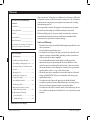
Cautions and Warnings
• Read this entire manual carefully before beginning installation. Save
these instructions.
• Use only Hunter replacement parts.
• To reduce the risk of personal injury, attach the fan directly to the
support structure of the building according to these instructions,
and use only the hardware supplied.
• To avoid possible electrical shock, before installing your fan,
disconnect the power by turning o the circuit breakers to the
outlet box and associated wall switch location. If you cannot lock
the circuit breakers in the o position, securely fasten a prominent
warning device, such as a tag, to the service panel.
• All wiring must be in accordance with national and local electrical
codes and ANSI/NFPA 70. If you are unfamiliar with wiring, use a
qualied electrician.
• To reduce the risk of personal injury, do not bend the blade
attachment system when installing, balancing, or cleaning the fan.
Never insert foreign objects between rotating fan blades.
• To reduce the risk of re, electrical shock, or motor damage, do not
use a solid-state speed control with this fan. Use only Hunter speed
controls.
For Your Records and Warranty
Assistance
Model Name: _____________________
Catalog/Model No.: ________________
Serial No.: _______________________
Date Purchased: ___________________
Where Purchased: _________________
For reference also attach your receipt or a
copy of your receipt to the manual.
Table of Contents
1 • Getting Ready ...................................................4
2 • Installing the Hanger Bracket...................5
3 • Assembling and Hanging the Fan..........6
4 • Setting the Remote Transmitter and
Receiver.................................................................7
5 • Wiring the Fan..................................................8
6 • Installing the Canopy and
Canopy Trim Ring............................................9
7 • Assembling the Blades.............................. 10
8 • Installing the Glass ...................................... 11
9 • Operating the Remote Control
and Mounting the Holder ....................... 12
10 • Operating and Cleaning
Your Ceiling Fan.......................................... 13
11 • Troubleshooting......................................... 14
Welcome

2
Hunter Fan Company 42015-01 • 02/15/05
3
42015-01 • 02/15/05 Hunter Fan Company
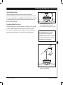
Mounting and Optional Accessories
Understanding Mounting
Hunter’s patented mounting system provides you maximum
installation exibility and ease. You can install your Hunter fan in one
of two ways, depending on ceiling height and your preference: Standard
or Angle mounting. e steps in this manual include instructions for
both mounting methods.
Considering Optional Accessories
Consider using Hunter’s optional accessories, including a wall-mounted
or remote speed control. To install and use the accessories, follow
the instructions included with each product. For quiet and optimum
performance of your Hunter fan, use only Hunter speed controls.
Standard Mounting hangs from
the ceiling by a downrod (included),
recommended for ceilings 8 feet or higher
Angle Mounting recommended for a
vaulted or angled ceiling
For ceilings higher than 8 feet, you
can purchase Hunter extension
downrods. All Hunter fans use sturdy
3/4” diameter pipe to assure stability
and wobble-free performance.

4
Hunter Fan Company 42015-01 • 02/15/05
5
42015-01 • 02/15/05 Hunter Fan Company
1 • Getting Ready
To install a ceiling fan, be sure you can do the following:
• Locate the ceiling joist or other suitable support in ceiling.
• Drill holes for and install wood screws.
• Identify and connect electrical wires.
• Lift 40 pounds.
If you need help installing the fan, your Hunter fan dealer can direct
you to a licensed installer or electrician.
Gathering the Tools
You will need the following tools for installing the fan:
• Electric drill with 9/64” bit
• Standard screwdriver
• Phillips-head screwdriver
• Wrench or pliers
Check Your Fan Parts
Carefully unpack your fan to avoid damage to the fan parts. Check
for any shipping damage to the motor or fan blades. If one of the fan
blades was damaged in shipment, return all the blades for replacement.
If any parts are missing or damaged, contact your Hunter dealer or call
Hunter Parts Department at 888-830-1326.
Preparing the Fan Site
Before you begin installing the fan, follow all the instructions in
the pullout sheet called “Preparing the Fan Site.” Proper ceiling fan
location and attachment to the building structure are essential for
safety, reliable operation, maximum e ciency, and energy savings.
Installing Multiple Fans?
If you are installing more than
one fan, keep the fan blades in
sets, as they were shipped.

4
Hunter Fan Company 42015-01 • 02/15/05
5
42015-01 • 02/15/05 Hunter Fan Company
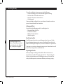
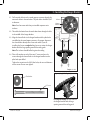
2 • Installing the Hanger Bracket
2-1. Drill two pilot holes into the wood support structure through the
outermost holes in the outlet box. e pilot holes should be 9/64”
in diameter.
Note: Your fan comes with four pre-installed neoprene noise
isolators.
2-2. read the lead wires from the outlet box down through the hole
in the middle of the hanger bracket.
2-3. Align the slotted holes in the hanger bracket with the pilot holes
you drilled in the wood support structure. For proper alignment
use slotted holes directly across from each other. If you are
installing the fan on an angled ceiling, be sure to orient the hanger
bracket with the large opening towards the ceiling peak.
Note: e isolators should be ush against the ceiling.
2-4. Place a at washer on each of the two 3” screws and pass the
screws through the slotted holes in the hanger bracket into the
pilot holes you drilled.
Tighten the screws into the 9/64” pilot holes; do not use lubricants
on the screws. Do not over tighten.
Flat Washer
3” Screw
Steps 2-2 – 2-4
For Angled Ceilings: Be sure to orient
the hanger bracket with the large
opening towards the ceiling peak.
Hanger
Bracket
Step 2-3 (Angled Ceiling Only)
Isolator

6
Hunter Fan Company 42015-01 • 02/15/05
7
42015-01 • 02/15/05 Hunter Fan Company
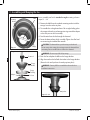
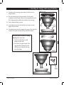
3 • Assembling and Hanging the Fan
You can assemble your fan for standard or angle mounting as shown
in steps 3-1 – 3-6.
3-1. Remove the label from the standard mounting washer inside the
canopy. Leave the washer in place.
3-2. To assemble fan to hang down from a at or angled ceiling, place
the canopy with washer, and canopy trim ring around the adapter
so that they rest on the fan assembly.
3-3. Feed the wires from the fan through the downrod.
3-4. Screw the downrod into the fan assembly. Tighten the allen head
set screw using the included allen wrench.
CAUTION: e downrod has a special coating on the threads.
Do not remove this coating; the coating prevents the downrod from
unscrewing. Once assembled, do not remove the downrod.
WARNING: Do not carry or lift fan by canopy.
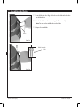
3-5. Raise the fan and place the ball into the hanger bracket.
3-6. Align the notch on the ball with the indent in the hanger bracket.
(Rotate the fan until you hear the notch pop into place.)
WARNING: Fan may fall if not assembled as directed in these
installation instructions.
Steps 3-5 – 3-6
Indent
Steps 3-2 – 3-4
Downrod
Canopy
(with Washer)
Canopy
Trim Ring
Set Screw
Canopy
Standard
Mounting
Washer
Step 3-1
Adapter
Label

6
Hunter Fan Company 42015-01 • 02/15/05
7
42015-01 • 02/15/05 Hunter Fan Company
4 • Setting the Remote Transmitter and Receiver
CAUTION: e remote control device complies with part 15 of the FCC rules.
Changes or modi cations not expressly approved by Hunter Fan Company could void
your authority to operate this equipment.
Operation is subject to the following two conditions:
1. is device may not cause harmful interference.
2. is device must accept any interference received, including interference that may
cause undesired operation.
Note: Use with a fan that incorporates an air gap switch (normal on-o wall switch).
WARNING: Maximum fan load is 1 Amp; maximum lamp is 100 Watts. Do not use
any speed control with this product.
You must now set the jumper switches in the remote transmitter and
receiver so that they match.
4-1. Change the position of the jumper switches in the transmitter
and the receiver. Be sure the position of the jumper switches
matches. If they don’t match, the controller will not function.
For instructions on how to set the jumper switches, read the box
below.
4-2. Install the included 12-volt battery into the transmitter.
Setting Jumper Switches
When two or more fans are located near each other, you may desire to have the
receiver/transmitter for each fan set to a di erent code, so that the operation of
one fan does not a ect the operation of the other fans.
In the transmitter you can access the jumpers from the battery compartment.
e jumpers are very small. You can move them most easily using a small pair of
pliers or tweezers. IMPORTANT! Before you change jumper switches, make sure
the battery is not connected to the transmitter.

8
Hunter Fan Company 42015-01 • 02/15/05
9
42015-01 • 02/15/05 Hunter Fan Company
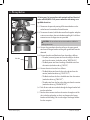
5 • Wiring the Fan
All wiring must be in accordance with national and local electrical
codes and ANSI/NFPA 70. If you are unfamiliar with wiring, use a
qualied electrician.
5-1. Disconnect the power by turning o the circuit breakers to the
outlet box and associated wall switch location.
5-2. To connect the wires, hold the bare metal leads together and place
a wire nut over them, then twist clockwise until tight. For all these
connections use the larger wire nuts provided.
CAUTION: Be sure no bare wire or wire strands are visible after
making connections.
5-3. Connect the ground wire from the ceiling to the green ground
wire from the hanger bracket and the green ground wire from the
downrod.
5-4. Connect the white and black wires from the ceiling as follows::
•
e white (common) power wire from the ceiling to the white
wire from the receiver (marked on red tag “NEUTRAL IN”)
• e black power wire from the ceiling to the black wire from
the receiver (marked on red tag “LIVE IN”)
5-5. Connect the wires from the fan as follows:
• e black/white wire from the fan to the red wire from the
receiver (marked on white tag “LIGHT OUT”)
• e black wire from the fan to the black wire from the receiver
(marked on white tag “FAN OUT”)
• e white wire from the fan to the white wire from the receiver
(marked on white tag “COMMON OUT”)
5-6. Push all wires and wire nuts back through the hanger bracket hole
into the outlet box.
5-7. Run the white antenna wire from the receiver through one of the
slots in the hanger bracket so that it rests between the hanger
bracket and the ceiling. Push it to the edge of the hanger bracket
for clear reception.
Wire Nut
Steps 5-3 – 5-7
Antenna

8
Hunter Fan Company 42015-01 • 02/15/05
9
42015-01 • 02/15/05 Hunter Fan Company
Steps 6-1 – 6-2
Canopy Trim
Ring
Canopy
Hanger Bracket
Step 6-3
Canopy
Screw
Steps 6-4 – 6-5
6 • Installing the Canopy and Canopy Trim Ring
6-1. Partially install two canopy screws (about 2 full turns) in the
hanger bracket.
6-2. Raise the canopy over the hanger bracket (For low pro le
installations, you will need to remove the canopy from the hook
rst). Align partially installed screws with key slots in canopy.
6-3. Twist canopy clockwise to secure.
6-4. Install third canopy screw in round hole on canopy. Securely
tighten all three screws.
6-5. Using both hands, push the canopy trim ring up to the top of the
canopy. e canopy trim ring will snap and lock into place.
Should you need to remove the canopy
trim ring, follow these steps:
1. Locate the tab indicators, small
bumps on top of tabs.
2. Press rmly on opposite sides of the
ring towards the canopy. e tabs
will ex out releasing the trim ring
from the canopy

10
Hunter Fan Company 42015-01 • 02/15/05
11
42015-01 • 02/15/05 Hunter Fan Company
7 • Assembling the Blades
7-1. Insert blade into slot. Align the holes on the blade with the holes
on the blade iron.
7-2. Attach the blade to the motor using the blade assembly screws.
Note: Do not use the middle hole on the blade.
7-3. Repeat for each blade.
Step 7-1
Step 7-2
Blade Assembly
Screw
Holes

10
Hunter Fan Company 42015-01 • 02/15/05
11
42015-01 • 02/15/05 Hunter Fan Company
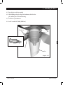
8 • Installing the Glass
8-1. Raise the glass to the fan assembly.
8-2. While holding up the glass, align the thumbscrew, the hole in the
glass, and the post on the motor housing.
8-3. Install three (3) thumbscrews.
8-4. Install 1 standard A-19 bulb (100W max).
umbscrew
Hole
Post
Glass
Steps 8-1 – 8-4

12
Hunter Fan Company 42015-01 • 02/15/05
13
42015-01 • 02/15/05 Hunter Fan Company
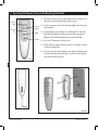
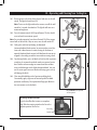
9 • Operating the Remote Control and Mounting the Holder
9-1. e remote transmitter has individual buttons for turning the fan
o and on and controlling the light and fan speed.
9-2. For best operation, start the fan by pressing high, then select your
desired speed.
9-3. e light button turns the light on to full brightness. To dim the
light, hold the light button down until you reach your desired
brightness. Push the light button again to turn o the light.
9-4. Press the OFF button to turn the fan o.
9-5. When necessary, replace the battery with a 12-volt type 23A, MN-
21 battery or equivalent.
9-6. You can mount the remote holder to any toggle switch plate with
the screws already in the switch plate. Or, you can simply mount
the remote holder on the wall.
Fan Light
Steps 9-1 – 9-4
Step 9-6
Step 9-5
Fan Speed
High
Fan Speed
Medium
Fan Speed
Low
Fan O

12
Hunter Fan Company 42015-01 • 02/15/05
13
42015-01 • 02/15/05 Hunter Fan Company
10 • Operating and Cleaning Your Ceiling Fan
10-1. Restore power at the main electrical panel and turn on the wall
switch. e light kit should turn ON.
Note: To turn on the light without the remote, turn o the wall
switch for 5 seconds, then back on. e light kit will turn on at
maximum brightness.
10-2. Press the remote control’s HIGH speed button. e fan should
start and reach its maximum speed.
Note: For everyday operation, leave the wall switch ON. If the remote
control will not be used for 5 days or more, turn the wall switch OFF.
10-3. Ceiling fans work best by blowing air downward
(counterclockwise blade rotation) in warm weather to cool the
room with a direct breeze. In winter, having the fan draw air
upward (clockwise blade rotation) will distribute the warmer air
trapped at the ceiling around the room without causing a draft.
10-4. For cleaning nishes, use a soft brush or lint-free cloth to prevent
scratching. A vacuum cleaner brush nozzle can remove heavier
dust. Remove surface smudges or accumulated dirt and dust
using a mild detergent and a slightly dampened cloth. You may
use an artistic agent, but never abrasive cleaning agents as they
will damage the nish.
10-5. Clean wood nish blades with a furniture polishing cloth.
Occasionally, apply a light coat of furniture polish for added
protection and beauty. Clean painted and high-gloss blades in
the same manner as the fan nish.
In warm weather, use
downward air ow pattern
In cold weather, use upward
air ow pattern
To Change Air ow Direction
Turn the fan o and let it come to a complete
stop. Slide the reversing switch on the fan to the
opposite position. Restart fan.
Reversing
Switch

14
Hunter Fan Company 42015-01 • 02/15/05
11 • Troubleshooting
Problem: Nothing happens; fan does not move.
1. Turn power on, replace fuse, or reset breaker.
2. Loosen canopy, check all connections according to the wiring the
fan section.
3. Check the plug connection in the switch housing.
4. Push motor reversing switch rmly up or down to ensure that the
switch is engaged.
Problem: Noisy operation.
1. Tighten the blade screws until snug.
2. Check to see if the blade is cracked. If so, replace all the blades.
3. Be sure that the glass is secure.
Problem: Excessive wobbling.
1. If your fan wobbles when operating, use the enclosed balancing kit
and instructions to balance the fan.
2. Tighten all blade and/or blade iron screws.
3. Turn power o , support fan very carefully, and check that the
hanger ball is properly seated.
If you need parts or service assistance, please call
888-830-1326 or visit us at our WEB site at
http://www.hunterfan.com.
Hunter Fan Company
2500 Frisco Avenue
Memphis, Tennessee 38114
-
 1
1
-
 2
2
-
 3
3
-
 4
4
-
 5
5
-
 6
6
-
 7
7
-
 8
8
-
 9
9
-
 10
10
-
 11
11
-
 12
12
-
 13
13
-
 14
14


Hunter Fan 42015-01 User manual
- Category
- Household fans
- Type
- User manual
Ask a question and I''ll find the answer in the document
Finding information in a document is now easier with AI
Related papers
-
 Hunter Fan 28789 Owner's manual
-
 Hunter Fan 21806 Owner's manual
-
 Hunter Fan 20492 User manual
-
 Hunter Fan 23967 Owner's manual
-
 Hunter Fan 27454 Owner's manual
-
 Hunter Fan 28199 User manual
-
 Hunter Fan 45007 User manual
-
 Hunter Fan 28007 Owner's manual
-
 Hunter Fan 28870 Owner's manual
-
 Hunter Fan 23926 Owner's manual