Page is loading ...

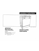
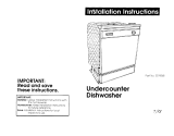
Undercounter Dishwasher
IMPORTANT:
Installer: Leave Installation
Instructions with the homeowner.
Homeowner: Keep Installation
Instructions for future reference.
Save Installation Instructions for
local electrical inspectots use.
Part No. 9741159
Before you start...
Proper installation is your
responsibility. Make sure you have
everything necessary for correct
installation. It is the personal
responsibility and obligation of the
customer to contact a qualified
installer to assure that electrical and
plumbing installation meet national
and local codes and ordinances.
Check location where dishwasher
will be installed. The location should
provide:
l
Easy access to water, electricity
and drainage.
l
Convenient loading -the best
position is left or right of kitchen
srnk.
* Opening that is square for proper
dishwasher operation and
appearance.
0 Cabinet front that is perpendicular
to floor.
l
Protection against freezing to
prevent the water inlet valve, water
lines to dishwasher, water lines in
dishwasher, and drain from
rupturing. (Ruptures from freezing
are not covered by the warranty.)
8 l/4” minimum clearance between
motor and flooring to prevent
motor overheating.
3pa

Electrical ground is required. See
Electrical requirements.
DO NOT install dishwasher over
carpeted flooring.
Proper electrical, drain and water
supply lines must be available or
must be installed as specified within
shaded-area to prevent interference
with dishwasher frame or other
components. See Electrical, Wate;
and Drain requirements. Plumbing
and wiring should not cross in front
of motor or dishwasher frame.
Product Damage
Protect dishwasher and water
lines leading to dishwasher
against freezing.
Failure to do so could cause
inlet valve, water lines leading
to dishwasher, water lines in
dishwasher and drain to
rupture.
Such ruptures are not covered
by warranty.
For installations where the
dishwasher will be left unused and
subjected to freezing temperatures,
it must be prepared as outlined in
your Use and Care Guide.
IMPORTANT: Observe all
governing codes and ordinances.
Electrical Shock Hazard
1 Electrical wiring and
components must not contact
any plumbing material or
drain hose.
1 Electrical wiring, water supply
line and drain line must not
contact any expose terminals
of dishwasher wiring.
1 Cabinet opening must
completely enclose sides, top
and back of dishwasher. A
side panel and wood top are
available from your
KitchenAid dealer to install
your dishwasher at the end of
a cabinet.
Failure to follow these
instructions may result in
qersonal injury from exposed
Miring.
Corner location - 2” min.
door to cabinets or wall
T!l
33-7116” min.
to 35” max.
underside
counter
height.
If 33-7/l 6”
height is
needed, the
leveling legs
will have to
be removed.
Cut 1” holes for
water, drain and
Grommet
electrical lines
required for
within shaded area.
electrical
cable hole
The unshaded
cut in metal
area must be free
cabinets
of pipes, drain
F
23-112”
min.%
cabinet
depth
hose or wires.
de- 24” opening width A
Figure I
*26” depth4
Figure 2
‘Whisper Quiet
insulation
compressed.
36”
countertop
height
LIE
23-718”
Personal Injury/Product
Damage Hazard
Avoid opening dishwasher
door before dishwasher is
installed.
Dishwasher, before it is
installed, may tip over when
door is opened, resulting in
personal injury or product
damage.
+ 20-314”
I_bp(
Tools and
materials needed
for installation:
Parts supplied for
installation:
2 counterlop anchor screws
Remove screws taped to upper right
hand mounting bracket.
Check that all parts were included.
l
electric drill
l
shutoff valve
l
Phillips
l
supply line fittings
screwdriver
l
1,3/8” NPT street
l
2 adjustable elbow (2 for
wrenches for
galvanized line) OR
copper fittings
90” compression
OR 2 pipe
elbow with 3/S” NPT
wrenches for
at one end for copper
galvanized or
line
iron fittings
l
9/l 6”, I.D. heat- and
l
pliers
detergent-resistant
l
measuring tape
hose and clamps OR
l
flat-blade
5/8”, 0-D. copper
screwdriver
tubing and fittings
.
3,411
nut driver or l
lo”, 5/8” 0.D.
Soft
socket wrench
copper tubing if high
l
wire cutters
loop drain is needed.
l
level
(See Page 3.)
. ,,, drill bit or hole
l
314
II .
strain relief
saw
l
tubing cutter
l
l/8” drill bit
l
pipe-joint compound
l
square
l
twist-on wire
l
112” O.D. copper
connectors
tubing OR 318”
l
electrical tape
We
Page 2

Electrical
requirements
Electrical Shock Hazard
l
Electrical ground is required
on this appliance.
l
If cold water pipe is
interrupted by plastic, non-
metallic gaskets or other
insulating materials, Do Not
use for grounding.
l
Do Not ground to a gas pipe.
l
Do Not modify the power
supply cord plug. If it does
not fit the outlet, have a
proper outlet installed by a
qualified electrician.
l
Do Not have a fuse in the
neutral or grounding circuit.
A fuse in the neutral or
grounding circuit could result
in an electrical shock.
l
Do Not use an extension cord
with this appliance.
l
Check with a qualified
electrician if you are in doubt
as to whether the appliance is
properly grounded.
Failure to follow these
instructions could result in
serious injury or death.
l
If codes permit and a separate
grounding wire is used, it is
recommended that a qualified
electrician determine that the
grounding path is adequate.
A single phase, 115volt, 60-Hz,
AC-only, 15- or 20-ampere, fused
electrical supply is required. Time-
delay fuse or circuit breaker is
recommended. It is recommended
that a separate circuit serving only
this appliance be provided.
It is the personal responsibility and
obligation of the customer to contact
a qualified electrician to assure that
the electrical installation is adequate
and is in conformance with the
National Electrical Code,
ANSVNFPA 70-latest edition and
local codes and ordinances.
The dishwasher can be connected
with flexible armored or non-metallic
sheathed copper cable (with
grounding wire).
A conduit connector must be
installed at junction box. Wire sizes
(COPPER WIRE ONLY) must
conform with the rating of the
dishwasher.
Flexible cord connection
Local codes may permit the use of a
U.L.-listed, flexible, three-conductor
cord terminated with a three-prong,
grounding-type plug. It is
recommended that cord kit, Part No.
675456, available from your
KitchenAid dealer or parts supplier,
be used. If the cord kit is not
available locally, the flexible cord
used must be a three-conductor, 16-
gauge cord that meets the National
Electrical Code, ANSVNFPA 70-
latest edition and local codes and
ordinances. The length of the cord
must not exceed six feet. It must be
routed so it does not touch the
dishwasher motor or the lower
portion of the dishwasher tub. A
grommet (Part No. 302797) must
cover the hole cut in a metal cabinet
for the flexible cord. The flexible cord
must be plugged into a mating three-
prong, grounding-type wall
receptacle, grounded in accordance
with the National Electrical Code,
ANSVNFPA 70-latest edition and
local ordinances. Follow instructions
packaged with the flexible cord.
Water
requirements
The hot water line to the dishwasher
must provide between 20-l 20 psi
water pressure. The hot water heater
should be.set to deliver 120°F
(minimum) water temperature to the
dishwasher (except as noted in your
Use and Care Guide) for best results.
Use l/2” O.D. copper tubing or 3/8”
galvanized pipe inlet line.
Dishwasher inlet valve has 3/8”
internal pipe thread.
Drain
requirements
Product Damage
l
The drain line connection to
the house plumbing must be
a minimum of 20” above the
floor. A lower drain
connection may result in
siphoning.
l
If the drain is routed to a
connection point less than
20” above the floor, the drain
line must form a loop 20”
above the floor. See Figure 3,
Page 4.
l
Do Not kink hose and copper
tubing.
Failure to provide either a 20”
minimum connection height or
a 20” high loop will result in
improper drainage and may
cause product damage.
The drain hose should be 9/l 6”
minimum I.D. flexible hose or 5/8”
O.D. copper tubing. A minimum of
22” flexible drain hose or a 12”
length of copper drain line with 12”
length of flexible hose added is
needed. Flexible hose, resistant to
heat and detergent, can be found at
plumbing, hardware or automotive
supply stores. Do Not use a drain
line or fittings less than l/2” I.D.
If drain line is copper, clamp a 12”
length of 9/16” I.D. flexible, heat-
and detergent-resistant hose to the
end of the copper drain line to
connect to the dishwasher valve.
Page 3

n
,
Figure 3-
If drain hose connection is less
than 20” above the floor, the hose
must form a loop using 5/8” O.D.
copper tubing 20” above the floor.
Make sure there are no kinks in the
hose or copper tubing.
Product Damage
l
All solder connections must
be made before the water line
is connected to the
dishwasher to prevent
damage to the inlet valve.
l
Do Not solder within 6” of
inlet valve. The plastic part of
the water inlet valve could be
damaged.
If connection to an air gap is
required, air gap kits are available
from local plumbing sources.
Recommended methods
to floor
I
Entry must be
above trap.
Figure 4
Install air gap according to
kit instructions.
Connect the air gap to a waste tee
or disposer using a rubber
connector. Most disposers have 718”
connectors or soecial connectors are
Now start . . .
With dishwasher in kitchen.
Disconnect electrical supply before
available at plumbing supply houses.
Be sure to remove the disposer
installing dishwasher.
knockout or plug before ’
connecting the drain hose.
Air-sac,
to floor
Alternate methods
Cut hose
Waste tee -&
20” min.
1
clearance
to floor
YH
20” min.
clearance
to floor
+
If local plumbing codes permit,
dishwasher drain hose may be
connected directly to a waste tee or
directly to a waste disposer.
The waste tee connection MUST be
made ahead of the trap and a
minimum of 20 inches above the
floor. Most disposers have 7/8”
connectors or special connectors
are available at plumbing supply
houses. Be sure to remove the
disposer plug before connecting
the drain hose.
24” opening width
1 I
Rough in water and drain lines to
the dishwasher cabinet opening
using one of the routing methods
shown. Cut
1”
hole in cabinet, rear
wall or floor for water and drain
lines.
Install a shutoff
valve in the water
line where it can
be easily used.
Flush water line into a
bucket to get rid of any
particles that may clog inlet valve.
Turn shutoff valve to “OFF’ position.
Check that there are no sharp
bends or kinks in water line that
might restrict water flow.
Install air gap. Attach drain hose to
air gap or waste tee. See “Drain
requirements.”
Page
4

Electrical Shock Hazard
l Disconnect electrical power
at the service panel (fuse box
or circuit box).
l Make sure that the water
supply line, drain line and
wiring do not touch any
exposed terminals of the
dishwasher wiring.
Failure to do so could result in
serious injury or death.
Cut a 1 -inch hole in the
cabinet for the electrical
wiring to pass through. If this hole is
cut in a wood cabinet, the hole
should be sanded until smooth. If
the hole is cut in a metal cabinet,
the hole must be covered by $I
grommet (Part No. 302797). Run
flexible cable from fused disconnect,
circuit breaker or junction box
through hole in cabinet. Cable
should extend 24” from back wall.
Remove the 2 screws below
the access panel. Pull
bottom of panel out and lifl up and
away from dishwasher. Set access
panel aside on a protective covering.
13.
Numbers
correspond
to steps.
8.
18.
Floor Damage
Slide dishwasher onto
cardboard or hardboard
before moving across floor.
Failure to do so may cause
damage to floor covering.
w w
The diz’ ’ ’ ’ ’
The dishwasher is shipped
I to be ir
to be installed in a 34”
cabinet opening. Mea:
cabinet opening. Measure height of
cabinet opening from I
cabinet opening from underside of
countertop to floor. Ad countertop to floor. Adjust leveling
legs to required openir legs to required opening height.
Place drain hose on the left
side of the cabinet opening
between the motor and the frame.
Latch dishwasher door. Grasp
dishwasher by the door frame and
push the dishwasher into the cabinet
opening. Be careful not to oush on
the dishwasher panels. Ce’nter
dishwasher in cabinet opening.
Check that front leveling legs are
firmly against the floor.
Page 5

n-l
back of dishwasher
m
alternate position
rear Gross channel
original position
Check to see if rear cross
channel contacts drain,
electrical or water lines. If the channel
contacts any line, pull dishwasher out
of opening. Do Not remove the
channel. Remove both cross channel
screws on the right-hand side.
Remove the bottom screw on the left-
hand side and loosen the top screw.
Align the bottom hole in the loose end
of channel with the higher hole in
frame and attach with screw. Tighten
the top screw on the other end of
channel. Repeat Step 9.
Align dishwasher door with
cabinet front, not doors.
compression elbow (3/8” N PT one
end). Connect street elbow to water
valve. Connect supply line to
compression elbow. If galvanized
pipe is used, use a second 3/8”
street elbow in place of the
compression elbow.
Page 6
/
dishwasher valve 9
d
h
at drain hose is not
kinked, crimped or contactins
electrical coi-mections. -
Place towel below
dishwasher valve area.
Remove red plug from dishwasher
valve. (A small amount of water may
still be in the valve area from quality
assurance testing.) Place hose
clamp over dishwasher valve.
Connect drain hose to valve and
secure with hose clamp. Check for
good fit and that there are no bends
or kinks in drain hose that could
restrict water flow.
top mounting
, brackets,
Do Not
drop
screws
into tub.
Open dishwasher and
remove foam shipping
pieces from upper corners of boor.
Remove bottom rack. Place a
newspaper or large sheet of paper
over bottom of dishwasher to protect
the pump area when securing
dishwasher to countertop.
Disconnect brackets
located at the top
corners of flange. Reattach brackets
with bracket end facing away from
dishwasher. Drill starter holes 3/4”
deep through bracket holes into the
underside of countertop using a l/8”
drill bit. Do Not exceed 3/4” depth.
Attach brackets to underside of
countertop. Make sure the screw
heads do not interfere with door.
You MUST secure dishwasher to
keep it from tilting when door is
opened or closed. Do Not drop
screws in dishwasher tub. If
screws should fall into pump,
pump and motor failure may
occur. Remove paper from bottom
of dishwasher.
If brackets cannot be attached to
countertop, attach dishwasher to
floor using l/4” lag bolts through
hole in each side of dishwasher
frame.
, equally spaced,
Open door approximately
3” and check for equal
spacing between inner door and tub
sides. If necessary, loosen screws
that fasten dishwasher to countertop
and shift tub. Retighten screws.
Place level against
interior flange as
shown. Level dishwasher front to
back and side to side by adjusting
leveling legs.

access oanels now, if
you plan to do so. hollow detailed
instructions provided on back cover.
Check door operation with either the
panels provided or custom panels.
Door should close easily without
slamming and should not open with
its own weight. If door closes too fast
from an open position, close door
and adjust door spring brackets
upward to a different hole. If door
falls open too quickly, close door and
move spring brackets downward.
Electrical Shock Hazard
Disconnect power before
making electrical connection.
Failure to do so could result in
electrical shock.
Remove terminal box cover. Install
conduit connector to box. Insert
power cable through grommet.
Connect the white wire of the power
supply cable to the white leads in
the terminal box with twist-on wire
connectors. Connect the black wire
of the power supply cable to the
black leads in the terminal box with
twist-on wire connectors.
Connect the grounding wire of the
power supply cable to the grounding
screw on the dishwasher frame.
Replace terminal box cover.
channel
Remove all shipping
materials. Do Not
remove the white plastic plug
buttons from the side of door or the
plastic bumpers from the front
corners of the lower rack. Do Not
remove the two spring retainers
attached to the heater (not included
on all models.)
Take a few minutes to
read the Use and Care
Guide to fully understand your new
dishwasher.
Check that all parts
have been installed and
no steps were skipped. Check that
you have all tools you started with.
CHECK ELECTRICAL
REQUIREMENTS. BE
SURE YOU HAVE CORRECT
ELECTRICAL SUP.PLY AND
RECOMMENDED GROUNDING
METHOD. Turn on electrical supply.
Turn on water supply.
Start dishwasher and
allow it to complete a
cycle. Check that dishwasher is
working properly and that there are
no water leaks.
Install top of access
oanel into channel and
rotate panel’towards dishwasher.
Reattach the access panel with two
screws. Check that the opening at
the bottom of access panel is clear
so air can circulate to cool motor.
If color of door is to be
changed or custom
panel installed, change the panel
now. See Use and Care Guide for
Instructions.
To get the most efficient use from
your new dishwasher, read your
KitchenAid Use and Care Guide.
Keep Installation Instructions and
Guide close to dishwasher for
easy reference.
Page 7

&tom-made
panels
Personal Injury Hazard
Handle metal edges of panels
carefully. Cut metal edges
may cause personal injury or
damage to other materials.
114”
THK.-@
r
18-
1316”*
z=----23-g” 6” -
n
1”
5116” routed top and side ed es
for panel more than l/4” thic
ii
.
*For Models: KUDA220T and
KUDA22ST-17-7/16”
**Raised door panel must have a 1”
minimum routed bottom edge to
prevent door panel from contacting the
access panel when door is opened.
Custom wood or other materials
should be l/4” thick. Thinner materials
will need to have a spacer panel
installed behind custom panel. If
custom panel is more than l/4” thick,
the outer edge will need to be routed
as shown. Custom wood panels need
a waterproof protective finish applied
to all sides and edges of panel.
Product Damage
Heavy duty door springs must
be used with custom panels
that weigh more than four
pounds.
Failure to follow this
instruction could cause
product damage.
After custom panels are installed,
check the door tension. The door
should be counterbalanced so it
doesn’t fall open or close when
opened. If the door closes from an
open position, adjust the door-
spring brackets upward to a
different hole. If door falls open too
quickly, move spring bracket
downward. If custom panels are
heavy, heavy-duty door springs are
available from your KitchenAid
dealer.
Part No. 9741159
01992 KitchenAid
Prepared by KitchenAid@, St. Joseph, Michigan
49085
Printed in U.S.A.
If the dishwasher
does not operate:
Check these points:
l
Is the door closed tightly and
latched securely?
l
Has the cycle been set correctly to
start the dishwasher?
l
Is the water turned on?
l
Has a house fuse blown or a
circuit breaker tripped?
l
Has electrical power been
interrupted?
Note: If the motor has stopped
because of overload, it will
automatically reset itself within a
few minutes.
If you need
assistance...
The KitchenAid Consumer
Assistance Center will answer any
questions about operating or
maintaining your appliances not
covered in the Installation
Instructions. The KitchenAid
Consumer Assistance Center is
open.24 hours a day, 7 days a
week. Just dial (800) 422-1230 -
the call is free.
When you call, you will need the
appliance model number and serial
number. Both numbers can be
found on the serial/rating plate
located on the front frame behind
the door.
If you need
service...
In the event that your KitchenAid
appliance should need service, call
the dealer from whom you
purchased the appliance or a
KitchenAid authorized service
company. A KitchenAid authorized
service company is listed in the
Yellow Pages of your telephone
directory under “Appliances -
Household - Major - Service or
Repair”. You can also obtain the
service company’s name and
telephone number by dialing, free,
within the continental United States,
telephone number, (800) 422-l 230.
A special operator will tell you the
name and number of your nearest
KitchenAid-authorized service
company.
/