
Installation and
Operation
Smart-UPS
®
SURT15k/20k
230 VAC
Stack/Rack-Mount 6U
suo0648a

This manual and the safety guide are available in English on the enclosed CD and the APC Web site, www.apc.com.
Uživatelská příručka a bezpečnostní pokyny jsou k dispozici v češtině na přiloženém CD a na webových stránkách APC -
www.apc.com.
Denne vejledning og sikkerhedsvejledningen er tilgængelige på dansk på den vedlagte CD og på APC's websted, www.apc.com.
Dieses Handbuch sowie die Sicherheitsrichtlinien sind in deutscher Sprache auf der beiliegenden CD und auf der Website von
APC unter www.apc.com verfügbar.
Este manual y la guía de seguridad están disponibles en español en el CD adjunto y en el sitio Web de APC, www.apc.com.
Ce manuel et le guide de sécurité sont disponibles en français sur le CD-ROM ci-inclus et sur le site Web d'APC, www.apc.com.
A használati utasítás és a biztonsági útmutató megtalálható magyarul a csatolt CD-n és az APC honlapján: www.apc.com.
Il presente manuale e la corrispondente Guida per la sicurezza sono disponibili in italiano sul CD-ROM allegato e sul sito Web
di APC all'indirizzo www.apc.com.
Deze handleiding en het veiligheidshandboek staan in het Nederlands op de bijgevoegde cd en op de APC-website:
www.apc.com.
En norsk versjon av denne håndboken og sikkerhetsveiledningen finnes på den vedlagte CD-en og på APCs webområde
www.apc.com.
Este manual e o guia de segurança estão disponíveis em português no CD incluso e no website da APC, www.apc.com.
Instrukcja obsługi oraz przewodnik bezpieczeństwa w języku polskim dostępne są na załączonej płycie CD i na stronie
internetowej APC, www.apc.com.
Denna manual och säkerhetsguide finns tillgänglig på svenska på medföljande CD och på APC:s webbsida, www.apc.com.
Bu kılavuzun ve güvenlik kılavuzunun Türkçe versiyonu ürünle birlikte verilen CD’de ve www.apc.com adresindeki APC web
sitesinde bulunmaktadır.
Panduan dan petunjuk keselamatan ini tersedia dalam Bahasa Inggris pada CD terlampir dan pada Situs APC, www.apc.com.
本書及び安全ガイドの日本語版は、同梱の CD 及び APC の Web サイト(www.apc.com)からご覧戴けます。
이 매뉴얼과 안전 가이드는 동봉된 CD 와 APC 웹사이트 www.apc.com 에서 한글로 이용할 수 있습니다 .
Англоязычный вариант данного руководства и
руководства по технике безопасности имеется на прилагаемом
компакт-диске, а также на сайте компании APC: www.apc.com.
APC, www.apc.com
您可以从随附的 CD 与 APC 网站 (www.apc.com)上获得本手册与安全指南的中文版本。
您可以從隨附的 CD 與 APC 網站 (www.apc.com)上獲得本手冊與安全指南的中文版本。
Το εγχειρίδιο αυτό και ο οδηγός ασφάλειας είναι διαθέσιμα στα ελληνικά στο CD που εσωκλείεται και στην ιστοσελίδα της
APC, www.apc.com.

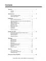
Contents
SURT15k/20k 230 VAC Stack/Rack-Mount 6U XLI/XLICH/XLI-CC
i
Overview . . . . . . . . . . . . . . . . . . . . . . . . . . . . . . . . . . . . . . . . . . . . . . . . 1
Inventory . . . . . . . . . . . . . . . . . . . . . . . . . . . . . . . . . . . . . . . . . . . . . . . 1
Hardware . . . . . . . . . . . . . . . . . . . . . . . . . . . . . . . . . . . . . . . . . . . . . . . 1
Specifications . . . . . . . . . . . . . . . . . . . . . . . . . . . . . . . . . . . . . . . . . . . . 2
Environmental Specifications . . . . . . . . . . . . . . . . . . . . . . . . . . . . . . 2
Physical Specifications . . . . . . . . . . . . . . . . . . . . . . . . . . . . . . . . . . . 2
Installation . . . . . . . . . . . . . . . . . . . . . . . . . . . . . . . . . . . . . . . . . . . . . . . 3
Stack or rack-mount front panel . . . . . . . . . . . . . . . . . . . . . . . . . . . . 3
PowerView installation for stack or rack-mount configurations . . 3
Stack configuration . . . . . . . . . . . . . . . . . . . . . . . . . . . . . . . . . . . . . . 4
Rack-mount configuration . . . . . . . . . . . . . . . . . . . . . . . . . . . . . . . . . 4
Install rails in rack . . . . . . . . . . . . . . . . . . . . . . . . . . . . . . . . . . . . . . . 4
Mount units in rack . . . . . . . . . . . . . . . . . . . . . . . . . . . . . . . . . . . . . . . 5
Route ethernet cable . . . . . . . . . . . . . . . . . . . . . . . . . . . . . . . . . . . . . 6
Install bezels . . . . . . . . . . . . . . . . . . . . . . . . . . . . . . . . . . . . . . . . . . . . 7
Accessories . . . . . . . . . . . . . . . . . . . . . . . . . . . . . . . . . . . . . . . . . . . . . 7
Optional accessories . . . . . . . . . . . . . . . . . . . . . . . . . . . . . . . . . . . . . 7
Hardwire the UPS . . . . . . . . . . . . . . . . . . . . . . . . . . . . . . . . . . . . . . . . . 8
Install input and output wiring trays in UPS rear panel . . . . . . . . . 9
Wiring Specifications . . . . . . . . . . . . . . . . . . . . . . . . . . . . . . . . . . . . 10
Input wiring options . . . . . . . . . . . . . . . . . . . . . . . . . . . . . . . . . . . . . 12
Output wiring options . . . . . . . . . . . . . . . . . . . . . . . . . . . . . . . . . . . 15
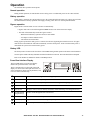
Operation . . . . . . . . . . . . . . . . . . . . . . . . . . . . . . . . . . . . . . . . . . . . . . . 17
Normal operation . . . . . . . . . . . . . . . . . . . . . . . . . . . . . . . . . . . . . . . 17
Battery operation . . . . . . . . . . . . . . . . . . . . . . . . . . . . . . . . . . . . . . . 17
Bypass operation . . . . . . . . . . . . . . . . . . . . . . . . . . . . . . . . . . . . . . . 17
Battery LED . . . . . . . . . . . . . . . . . . . . . . . . . . . . . . . . . . . . . . . . . . . . 17
PowerView Interface Display . . . . . . . . . . . . . . . . . . . . . . . . . . . . . . 17
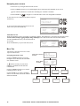
Navigating menu screens . . . . . . . . . . . . . . . . . . . . . . . . . . . . . . . . 18
Menu Tree . . . . . . . . . . . . . . . . . . . . . . . . . . . . . . . . . . . . . . . . . . . . . 18
Sub menu screens . . . . . . . . . . . . . . . . . . . . . . . . . . . . . . . . . . . . . . 19
Start-Up . . . . . . . . . . . . . . . . . . . . . . . . . . . . . . . . . . . . . . . . . . . . . . . . 21
Connect load to UPS . . . . . . . . . . . . . . . . . . . . . . . . . . . . . . . . . . . . 21
Connect power to UPS and load . . . . . . . . . . . . . . . . . . . . . . . . . . . 21
Communication port . . . . . . . . . . . . . . . . . . . . . . . . . . . . . . . . . . . . . 21
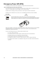
Emergency Power Off (EPO) . . . . . . . . . . . . . . . . . . . . . . . . . . . . . . . 22

SURT15k/20k 230 VAC Stack/Rack-Mount 6U XLI/XLICH/XLI-CC
ii
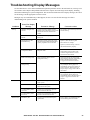
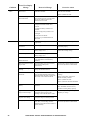
Troubleshooting Display Messages . . . . . . . . . . . . . . . . . . . . . . . . . 23
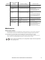
Maintenance . . . . . . . . . . . . . . . . . . . . . . . . . . . . . . . . . . . . . . . . . . . . 25
Replace battery modules . . . . . . . . . . . . . . . . . . . . . . . . . . . . . . . . . 25
Service. . . . . . . . . . . . . . . . . . . . . . . . . . . . . . . . . . . . . . . . . . . . . . . . . 26
Transport the unit . . . . . . . . . . . . . . . . . . . . . . . . . . . . . . . . . . . . . . . 26
Contact Information . . . . . . . . . . . . . . . . . . . . . . . . . . . . . . . . . . . . . . 26
Two-Year Warranty. . . . . . . . . . . . . . . . . . . . . . . . . . . . . . . . . . . . . . . 27

SURT15k/20k 230 VAC Stack/Rack-Mount 6U XLI/XLICH/XLI-CC 1
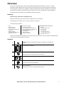
Overview
The APC
®
by Schneider Electric Smart-UPS
®
SURT15k/20k Stack/Rack-Mount 6U 230 VAC is a high
performance uninterruptible power supply (UPS). It provides protection for electronic equipment from utility
power blackouts, brownouts, sags, and surges; small utility fluctuations and large disturbances. The UPS also
provides battery backup power until utility power returns to safe levels or the batteries are fully discharged.
The UPS and the external battery pack (XLBP) are packaged separately.
Inventory
Read the Safety Guide before installing the UPS.
Inspect the UPS upon receipt. Notify the carrier and dealer if there is damage.
The packaging is recyclable; save it for reuse or dispose of it properly.
Check the package contents:
NOTE: The model and serial numbers are located on a small, rear panel label. For some models, an additional label
is located on the chassis under the front bezel.
Hardware
•UPS
• Input wiring tray
• Output wiring tray
• PowerView display module
• Front bezel
• DB9 serial cable
• Ethernet jumper cable for rear
panel network access
• Literature kit containing:
– Product documentation
– Smart-UPS
®
RT User Manuals CD
– Network Management Card Utility CD
– Network Management Card
documentation
– Safety information
– Warranty information
• Rack-mount models also include:
–Rail Kit
– Four ornamental screws
– Two cage nuts
– Two rail cleats
– Four pan head screws
– Two rack-mount brackets
– Eight flat head screws
8
Flat head screws for securing rack-mount or tie brackets to the UPS and
XLBP
2
rack-mount or tie brackets
4
Rack-mount units:
pan head screws for securing rail cleats to the UPS
2
rail cleats
2
Rack-mount units:
cage nuts for rack-mount installation
4
Rack-mount units:
ornamental screws for securing the UPS to the rack

SURT15k/20k 230 VAC Stack/Rack-Mount 6U XLI/XLICH/XLI-CC2
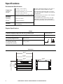
Specifications
Environmental Specifications
Physical Specifications
Temperature
Operating
Storage
0° to 40° C (32° to 104° F)
-15° to 45° C (5° to 113° F)
charge the UPS battery every six months
30° to 70° C (86° to 158° F)
charge the UPS battery every three months
This unit is intended for indoor use only. Select a
location sturdy enough to handle the weight.
Do not operate the UPS where there is excessive
dust or the temperature or humidity are outside the
specified limits.
This unit has front to rear airflow. Allow adequate
space for proper ventilation.
Environmental factors impact battery life. High
temperatures, poor utility power, and frequent,
short duration discharges will shorten battery life.
Maximum
Elevation
Operating
Storage
3,000 m (10,000 ft)
15,240 m (50,000 ft)
Humidity
0 to 95% relative humidity,
non-condensing
Weight
Combined shipping weight UPS and one XL battery pack 314.09 kg (691 lb)
Combined weight (no packing material) UPS and one XL battery pack
247.73 kg (545 lb)
UPS (no packing material)
66 kg (145 lb)
XL Battery Pack
(no packing material)
with eight battery modules
181 kg (400 lb)
Dimensions
773 mm
30.4 in
432 mm
17 in
263 mm
10.4 in
102 mm
4 in
482 mm
19 in
465 mm
18.3 in
suo0642a

SURT15k/20k 230 VAC Stack/Rack-Mount 6U XLI/XLICH/XLI-CC 3
Installation
Stack or rack-mount front panel
PowerView installation for stack or rack-mount configurations
Prior to attaching the PowerView to the UPS:
1. Loosen the two bracket screws on the back of the PowerView module.
a. Slide the bracket to the position that will accommodate the screw holes on the UPS.
b. Tighten the screws on the bracket.
2. Secure the PowerView to the UPS using the two thumb screws attached to the PowerView.
suo0643a
PowerView
Cold Start/EPO Reset
SmartSlot with Network Management Card
PowerView Cable Connector
Serial Port
Interface Display RJ45 Connector (pass through to rear panel RJ45 connector)
Ethernet port 10/100 Base-T
suo
0645a
suo0646a
Connect the PowerView cable to the PowerView connector on the UPS.
suo064
4a

SURT15k/20k 230 VAC Stack/Rack-Mount 6U XLI/XLICH/XLI-CC4
Stack configuration
The UPS and the XLBPs must be connected with ground wires. Refer to the XLBP user manual for details.
Rack-mount configuration
Install rails in rack
For details on rail installation refer to the instructions included in the rail kit package.
Install rack-mount brackets
Four flat head screws must be used to secure each
rack-mount bracket to the unit.
Install rail cleats
Two pan head screws must be used to secure each rail cleat
to the unit.
8x
suo0663a
Always place the UPS above the XLBP(s) in a stack
configuration.
Total stack configuration height is recommended NOT to exceed
18U. This is the equivalent of two XLBPs and one UPS.
Four screws must be used to secure each tie bracket to the units,
(see diagram).
For detailed instructions on installing batteries, the battery
doors, refer to the Rack-mount configuration section of this
manual.
Refer to the Rack-mount configuration section in this manual for
cable routing and bezel installation details.
Tie Brackets
(included with XLBP)
4x
suo0664a
2x
suo0665a

SURT15k/20k 230 VAC Stack/Rack-Mount 6U XLI/XLICH/XLI-CC 5
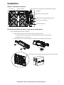
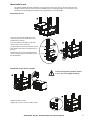
Mount units in rack
The UPS and XLBP should be installed at or near the bottom of the rack. Always place the UPS above the
XLBP(s). Batteries must be removed from the XLBP(s) prior to installing the unit(s) in a rack. Refer to the
instructions on the packaging for details on removing the batteries from the XLBP.
Install units in rack
Secure the UPS and the XLBP in the rack
using the cage nuts and ornamental screws
included in the package.
Four ornamental screws and two cage nuts
must be used to secure each unit.
A cage nut must be used in the top hole of each
rack-mount bracket when securing the unit in
the rack.
The bottom hole of each rack-mount bracket
must be secured using an ornamental screw in
the threaded hole.
Install and connect battery modules
Connect all eight battery modules. Failure
to do so may cause equipment damage.
Replace the battery doors.
Tighten the screws to secure the battery doors.
suo0667a
4x
4x
suo0666a
7 holes
7 holes
suo0668a
suo066
9a

SURT15k/20k 230 VAC Stack/Rack-Mount 6U XLI/XLICH/XLI-CC6
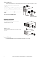
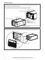
Route ethernet cable
Ethernet cable wiring rear panel access
Locate the RJ45 connector and the ethernet port on the front panel of the UPS. Connect the ethernet jumper cable
(included), to the RJ45 connector and the ethernet port.
Connect a network cable (not included), to the RJ45 connector on the rear panel of the UPS.
There is an internal ethernet cable that connects the front and rear panel RJ45 connectors.
Ethernet cable wiring front panel
Cables that are connected to the UPS for front panel access must be routed through one of the notches on the bezel.
suo0670a
RJ45 Connector
Ethernet Cable connected to rear
panel RJ45 connector
Ethernet Cable
Ethernet Jumper Cable
Internal pass through ethernet cable connecting front and
rear panel RJ45 connectors
Ethernet
Port
suo0651a
Ethernet Cable
Ethernet Port

SURT15k/20k 230 VAC Stack/Rack-Mount 6U XLI/XLICH/XLI-CC 7
Install bezels
Accessories
Install accessories prior to connecting power to the UPS.
• Refer to the APC Web site, www.apc.com for available accessories.
• User documentation for the Network Management Card installed on this UPS is available on the Utility CD
included with this unit.
Optional accessories
• Maintenance bypass
• SURT192RMXLBP2
• Equipment cart
Install a bezel on the UPS and XLBP(s).
suo0650a

SURT15k/20k 230 VAC Stack/Rack-Mount 6U XLI/XLICH/XLI-CC8
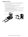
Hardwire the UPS
Wiring must be performed by a qualified electrician. Adhere to all local and national electrical codes.
1. For input wiring only, install a utility circuit breaker in accordance with local electrical codes.
2. Switch the utility circuit breaker OFF.
3. Remove the appropriate circular knockouts from the input and output wiring trays.
4. Remove the screws that secure the covers and take the covers off of the trays.
5. Remove the five screws that secure the strain relief bar.
6. Remove the appropriate jumpers for input power source compatibility and output wiring options, (refer to
“Wiring Specifications” on page 10 in this manual).
7. Insert the cables through the knockout holes to the terminal blocks. Connect the ground terminal first,
(refer to “Wiring Specifications” on page 10 in the this manual).
8. Use an appropriate strain-relief (not supplied), on the hardwired input and output power cables.
9. Replace the wiring tray covers. Failure to do so may result in personal injury or equipment damage.
10. Install the wiring trays, (refer to graphics below).
11.
5x
suo0672a
SUO0671A
Input Wiring Tray
Output Wiring Tray
Strain Relief Bar

SURT15k/20k 230 VAC Stack/Rack-Mount 6U XLI/XLICH/XLI-CC 9
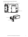
Install input and output wiring trays in UPS rear panel
suo0673a
suo0649a
Input Wiring Tray
Ground
EPO Port
Cold Start/EPO Reset
Output Wiring Tray
Ground
RJ45
Connector
Input Wiring Tray
Output Wiring Tray
XLBP Connector

SURT15k/20k 230 VAC Stack/Rack-Mount 6U XLI/XLICH/XLI-CC10
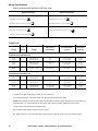
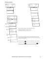
Wiring Specifications
Adhere to national and local electrical codes when wiring.
*Terminal screw tightening torque: 4.5 Nm (40 lb-in) minimum
**Use cables and input circuit breakers rated for specifications listed in these tables.
NOTE: Units configured for three phase input and single phase output operation, the entire load connected to the
UPS will transfer to L1 and Neutral of the three phase input when the UPS is operating in Bypass mode.
***The current is specified at nominal input voltage.
The acceptable input frequency range is 40 Hz to 70 Hz.
The output frequency is user selectable. Refer to the PowerView display menu screens for available options.
Input Connections Output Connections
Main Input
Single-Phase: Wire to L1, N, and
Three-Phase: Wire to L1, L2, L3, N, and
Hardwire
Single-Phase: Wire to L1, N, and
Three-Phase: Wire to L1, L2, L3, N, and
Bypass Input (optional)
Single-Phase: Wire to B1, N, and
Three-Phase: Wire to B1, B2, B3, N, and
Single-phase PDU
XL battery pack PDU to UPS: Wire L1, N,
Single Feed
Wiring
Number
of
Phases Voltage
Current
Full Load***
(maximum)
External Input
Circuit Breaker
(typical)
Wire Size
(typical)*
SURT15K XLI/XLICH/XLI-CC
Input
Output
1
1
220/230/240 VAC
220/230/240 VAC
83 A
66 A
100 A each phase
not required
35 mm
2
25 mm
2
Input
Output
3
1
380/400/415 VAC
220/230/240 VAC
28 A each phase
66 A
100 A each phase**
not required
35 mm
2**
25 mm
2
Input
Output
3
3
380/400/415 VAC
380/400/415 VAC
28 A each phase
22 A each phase
35 A or 40 A each phase
not required
6 mm
2
6 mm
2
SURT20K XLI/XLICH/XLI-CC
Input
Output
1
1
220/230/240 VAC
220/230/240 VAC
105 A
87 A
125 A each phase
not required
50 mm
2
35 mm
2
Input
Output
3
1
380/400/415 VAC
220/230/240 VAC
35 A each phase
87 A
125 A each phase**
not required
50 mm
2**
35 mm
2
Input
Output
3
3
380/400/415 VAC
380/400/415 VAC
35 A each phase
29 A each phase
50 A each phase
not required
10 mm
2
10 mm
2

SURT15k/20k 230 VAC Stack/Rack-Mount 6U XLI/XLICH/XLI-CC 11
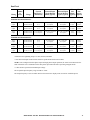
*Terminal screw tightening torque: 4.5 Nm (40 lb-in) minimum
**Use cables and input circuit breakers rated for specifications listed in these tables.
NOTE: Units configured for three phase input and single phase output operation, the entire load connected to the
UPS will transfer to L1 and Neutral of the three phase input when the UPS is operating in Bypass mode.
***The current is specified at nominal input voltage.
The acceptable input frequency range is 40 Hz to 70 Hz.
The output frequency is user selectable. Refer to the PowerView display menu screens for available options
Dual Feed
Wiring
Number
of
Phases Voltage
Current
Full Load***
(maximum)
External Input
Circuit Breaker
Mains (typical)
External Input
Circuit Breaker
Bypass (typical)
Wire
Size
Mains*
(typical)
Wire
Size
Bypass*
(typical)
SURT15K XLI/XLICH/XLI-CC
Input
Output
1
1
220/230/240 VAC
220/230/240 VAC
83 A
66 A
100 A each phase
not required
100 A each phase
not required
35 mm
2
25 mm
2
35 mm
2
25 mm
2
Input
Output
3
1
380/400/415 VAC
220/230/240 VAC
28 A each phase
66 A
35 A or 40 A each phase
not required
100 A each phase**
not required
6 mm
2
25 mm
2
35 mm
2**
25 mm
2
Input
Output
3
3
380/400/415 VAC
380/400/415 VAC
28 A each phase
22 A each phase
35 A or 40 A each phase
not required
35 A or 40 A each phase
not required
6 mm
2
6 mm
2
6 mm
2
6 mm
2
SURT20K XLI/XLICH/XLI-CC
Input
Output
1
1
220/230/240 VAC
220/230/240 VAC
105 A
87 A
125 A each phase
not required
125 A each phase
not required
50 mm
2
35 mm
2
50 mm
2
35 mm
2
Input
Output
3
1
380/400/415 VAC
220/230/240 VAC
35 A each phase
87 A
50 A each phase
not required
125 A each phase**
not required
10 mm
2
35 mm
2
50 mm
2**
35 mm
2
Input
Output
3
3
380/400/415 VAC
380/400/415 VAC
35 A each phase
29 A each phase
50 A each phase
not required
50 A each phase
not required
10 mm
2
10 mm
2
10 mm
2
10 mm
2

SURT15k/20k 230 VAC Stack/Rack-Mount 6U XLI/XLICH/XLI-CC12
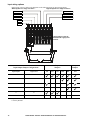
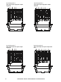
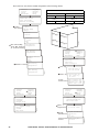
Input wiring options
Input wiring overview: Refer to the diagrams on the following pages for input wiring options.
I
Input/Output Jumper Configurations
Input
Jumpers
Output
Jumpers
Power I/O Configuration
Input:Output
Separate
Bypass Feed
SJ1 SJ2 SJ3 MSJ BSJ OSJ
1:1** No **
1:1 Yes
3:1 No
3:1 Yes
3:3 No
3:3 Yes
* Optional
** Factory Default
BSJ
B3
B2B1L1L2
L3NEUGND
MSJ
SJ3
SJ2
SJ1
suo0675a
Main Input Power Single and Three
Bypass Input Power Single and Three
Ground
Neutral
Main Phase 1
Bypass Phase 1
Main Phase 2
Main Phase 3
Bypass Phase 2
Bypass Phase 3
Labeled jumpers must be
installed in the appropriate
locations.

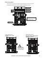
SURT15k/20k 230 VAC Stack/Rack-Mount 6U XLI/XLICH/XLI-CC 13
MSJ
B3B2B1L1L2L3NEUGND
BSJ
suo0677a
MSJ
SJ2
SJ1
SJ3
B3
B2B1L1L2
L3
NEUGND
BSJ
suo0674a
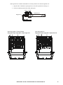
Ensure ground wire conductor and insulator are securely fastened. To connect the ground wire:
1. Strip the cable of insulation, exposing the wire. Secure the exposed wire with lug “A”.
2. Secure the insulated portion of the cable with lug “B”.
Input wiring option 2
Single phase input, single phase output, dual feed
Input wiring option 1 Factory Default
Single phase input, single phase output, single feed
Lug A
Lug B
Insulated wire
Stripped wire

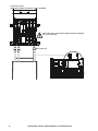
SURT15k/20k 230 VAC Stack/Rack-Mount 6U XLI/XLICH/XLI-CC14
BSJ
B3
B2B1L1L2
L3NEUGND
suo0679a
B3
B2B1L1L2
L3NEUGND
suo6781a
B3
B2B1L1L2
L3NEUGND
BSJ
SJ1
suo0678a
Input wiring option 3
Three phase input, single phase output,
single feed
SJ3
SJ2
SJ1
B3
B2B1L1L2
L3
NEUGND
suo0680a
Input wiring option 4
Three phase input, single phase output,
dual feed
Input wiring option 5
Three phase input, three phase output,
single feed
Input wiring option 6
Three phase input, three phase output, dual
feed

SURT15k/20k 230 VAC Stack/Rack-Mount 6U XLI/XLICH/XLI-CC 15
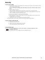
Output wiring options
Output wiring overview. Refer to the diagrams on the following pages for output wiring options.
Labeled jumpers and connectors must be installed in the appropriate locations.
N
OSJ
L3 L2 L1
suo0682a
Neutral
Ground
Output Phase 2
Output Phase 1
Output Phase 3
PDU Terminals
Factory Default Configuration
Output Shorting Jumper (OSJ)
for single phase output
OSJ
N
L3
L2 L1
suo0683a
N
L3
L2 L1
suo0684a
Output hardwire option 1
Single phase hardwire output
connection
Output hardwire option 2
Three phase hardwire output connection
XLBP PDU not connected
Output shorting jumper (OSJ) removed
Ensure the OSJ is
secured to the output
wiring tray using the
five screws provided.

SURT15k/20k 230 VAC Stack/Rack-Mount 6U XLI/XLICH/XLI-CC16
OSJ
N
L3
L2
L1
suo0685a
Output PDU option
Single phase output connection to battery pack PDU
Ensure the OSJ is secured to the output wiring tray using the
five screws provided.
PDU connectors
XLBP
Page is loading ...
Page is loading ...
Page is loading ...
Page is loading ...
Page is loading ...
Page is loading ...
Page is loading ...
Page is loading ...
Page is loading ...
Page is loading ...
Page is loading ...
-
 1
1
-
 2
2
-
 3
3
-
 4
4
-
 5
5
-
 6
6
-
 7
7
-
 8
8
-
 9
9
-
 10
10
-
 11
11
-
 12
12
-
 13
13
-
 14
14
-
 15
15
-
 16
16
-
 17
17
-
 18
18
-
 19
19
-
 20
20
-
 21
21
-
 22
22
-
 23
23
-
 24
24
-
 25
25
-
 26
26
-
 27
27
-
 28
28
-
 29
29
-
 30
30
-
 31
31


APC SURT15KRMXLI + Service Bundle 3 Specification
- Type
- Specification
- This manual is also suitable for
Ask a question and I''ll find the answer in the document
Finding information in a document is now easier with AI
Related papers
-
APC SUA029 User manual
-
APC SMX040 User manual
-
Schneider Electric SUA2200XLI/KIT User manual
-
APC Smart-UPS RC 3000VA User manual
-
Schneider Electric APCRBC115 User manual
-
APC SUA750RMI1U/KIT User manual
-
-
-
-
APC RT XLI/XLICH User manual
Other documents
-
Schneider Electric Smart-UPS User manual
-
American Power Conversion 8000 VA User manual
-
Schneider Electric Easy UPS On-Line User manual
-
Support APC User guide
-
Tripp Lite SU6000XFMR2U Owner's manual
-
Allen-Bradley 1609-P10000E User manual
-
-
-
-