Page is loading ...

MODEL 54
FR-N, FR-P
FIRE RIBBON
Unvented (Vent-Free) Gas Fireplace
Owner’s Operation and Installation Manual
WARNING: If the information in this manual
is not followed exactly, a fire or explosion
may result causing property damage,
personal injury, or loss of life.
— Do not store or use gasoline or other
flammable vapors and liquids in the
vicinity of this or any other appliance.
— WHAT TO DO IF YOU SMELL GAS
• Donottrytolightanyappliance.
• Donottouchanyelectricalswitch;do
not use any phone in your building.
• Immediately call your gas supplier
from a neighbor’s phone. Follow the
gas supplier’s instructions.
• Ifyoucannotreachyourgassupplier,
call the fire department.
— Installation and service must be
performed by a qualified installer,
service agency, or the gas supplier.
This is an unvented gas-fired heater. It uses
air (oxygen) from the room in which it is
installed. Provisions for adequate combus-
tion and ventilating air must be provided.
Refer to page 4, Air for Combustion and
Ventilation.
INSTALLER: Leave this manual with the
appliance.
CONSUMER: Retain this manual for future
reference.
This appliance may be installed in an
aftermarket,* permanently located, manu-
factured (mobile) home, where not prohib-
ited by local codes.
This appliance is only for use with the type
of gas indicated on the rating plate. This
appliance is not convertible for use with
other gases.
* Aftermarket: Completion of sale, not for purpose of resale, from
the manufacturer
WARNING: Improper installation, adjust-
ment, alteration, service, or maintenance
can cause injury or property damage. Refer
to this manual for correct installation and
operational procedures. For assistance or
additional information consult a qualified in-
staller, service agency, or the gas supplier.
This fireplace has been tested and approved
by OMNI-Test
Report # 0321GF008S
Laboratories, Inc. under ANSI
Z21.11.2 2019 Unvented Gas-Fired Room
Heaters.

2
TABLE OF CONTENTS
Safety Information ........................................................ 2
Local Codes
.................................................................. 3
Locating Firebox
........................................................... 4
Product Dimensions
...................................................... 4
Air For Combustion and Ventilation
............................ 4
Installation
..................................................................... 7
Built-In Fireplace Installation
....................................... 8
Operating Fireplace
..................................................... 11
Inspecting Burners
...................................................... 15
Cleaning and Maintenance
.......................................... 16
Troubleshooting
.......................................................... 17
Wiring Diagram
.......................................................... 21
Specifications
.............................................................. 21
Parts List and Illustrated Parts Breakdown
................. 22
Warranty Information
.................................. Back Cover
SAFETY INFORMATION
DANGER: Carbon monoxide poisoning
may lead to death!
Carbon Monoxide Poisoning: Early signs of carbon
monoxide poisoning resemble the flu, with headaches,
dizziness, or nausea. If you have these signs, the fireplace
may not be working properly. Get fresh air at once! Have
fireplace serviced. Some people are more affected by carbon
monoxide than others. These include pregnant women,
people with heart or lung disease or anemia, those under
the influence of alcohol, and those at high altitudes.
Propane/LP Gas: Propane/LP gas is odorless. An odor-
making agent is added to the gas. The odor helps you detect
a gas leak. However, the odor added to the gas can fade.
Gas may be present even though no odor exists.
Make certain you read and understand all warnings. Keep
this manual for reference. It is your guide to safe and proper
operation of this fireplace.
WARNING: Any change to this heater
or its controls can be dangerous.
WARNING: Do not allow fans to blow
directly into the fireplace. Avoid any drafts
that alter burner flame patterns. Ceiling
fans can create drafts that alter burner
flame patterns. Altered burner patterns can
cause sooting.
WARNING: Do not use a blower insert,
heat exchanger insert, or other accessory
not approved for use with this fireplace.
Due to high temperatures, the appliance
should be located out of traffic and away
from furniture and draperies.
IMPORTANT: Read this owner’s manual
carefully and completely before trying to
assemble, operate, or service this fireplace.
Improper use of this fireplace can cause
serious injury or death from burns, fire,
explosion, electrical shock, and carbon
monoxide poisoning.
IMPORTANT: A barrier designed to reduce
the risk of burns from the hot viewing glass
is provided with this appliance and shall be
installed for the protection of children and
other at-risk individuals.
If the barrier becomes damaged, the barrier
shall be replaced with the manufacturer's
barrier for this appliance.

3
Do not place clothing or other flammable
material on or near the appliance. Never
place any objects on the heater.
Fireplace front and sides become very hot
when running fireplace. Keep children and
adults away from hot surfaces to avoid
burns or clothing ignition. Fireplace will
remain hot for a time after shutdown. Allow
surfaces to cool before touching.
Carefully supervise young children when
they are in the room with fireplace. When
using the hand-held remote accessory,
keep selector switch in the OFF position to
prevent children from turning on burners
with remote.
Keep the appliance area clear and free from
combustible materials, gasoline, and other
flammable vapors and liquids.
1. This appliance is only for use with the type of gas
indicated on the rating plate. This appliance is not
convertible for use with other gases.
2. Do not place propane/LP supply tank(s) inside any
structure. Locate propane/LP supply tank(s) outdoors
(propane/LP units only).
3. If you smell gas
• shutoffgassupply
• donottrytolightanyappliance
•
do not touch any electrical switch; do not use any
phone in your building
• immediatelycallyourgassupplierfromaneighbor’s
phone.Followthegassupplier’sinstructions
• ifyoucannotreachyourgassupplier,callthere
department
4. This fireplace shall not be installed in a bedroom or
bathroom.
5. Do not use this fireplace as a wood-burning fire-
place.
6. To prevent the creation of soot, follow the instructions
in Cleaning and Maintenance section.
Keep the appliance area clear and free from
combustible materials, gasoline and other
flammable vapors and liquids.
7. Before using furniture polish, wax, carpet cleaner, or
similar products, turn heater off. If heated, the vapors
from these products may create a white powder residue
within burner box or on adjacent walls or furniture.
8. This fireplace needs fresh air ventilation to run prop-
erly. This fireplace has an Oxygen Depletion Sensing
(ODS) safety shutoff system. The ODS shuts down
the fireplace if not enough fresh air is available. See
Air for Combustion and Ventilation, pages 4 through
6. If fireplace keeps shutting off, see Troubleshooting,
pages 17 through 20.
9. Do not run fireplace
• where flammable liquids or vapors are used or
stored
• underdustyconditions
10. Do not use this fireplace to cook food or burn paper or
other objects.
11. Do not use fireplace if any part has been exposed to
orunder water.Immediatelycallaqualiedservice
technician to inspect the fireplace and to replace any
part of the control system and any gas control which
has been under water.
12. Turn fireplace off and let cool before servicing. Only
a qualied service person should service and repair
fireplace.
13. Operating fireplace above elevations of 4,500 feet
could cause pilot outage.
14. To prevent performance problems, do not use propane/
LP fuel tanks of less than 100 lbs. capacity.
15. Provideadequateclearancesaroundairopenings.
LOCAL COdES
Install and use fireplace with care. Follow all local codes.
In the absence of local codes, use the latest edition of The
National Fuel Gas Code ANSI Z223.1/NFPA 54*.
*Available from:
American National Standards Institute, Inc.
1430 Broadway
New York, NY 10018
National Fire Protection Association, Inc.
Batterymarch Park
Quincy, MA 02269
State of Massachusetts: The installation must
be made by a licensed plumber or gas fitter in the
Commonwealth of Massachusetts.
Sellers of unvented propane or natural gas-fired
supplemental room heaters shall provide to each
purchaser a copy of 527 CMR 30 upon sale of
the unit.
Vent-free gas products are prohibited for bedroom
and bathroom installation in the Commonwealth of
Massachusetts.

4
PLANNING
Carefully plan where you will install the firebox. This will
save time and money later during the installation process.
Before installing, consider the following:
1. Determine the best firebox location. Allow for wall and
ceiling clearances (see Built-In Fireplace Installation,
page 8).
2. Allow for location of control switch in wall adjacent to
fireplace. There is 9 linear feet of provided wire.
3.
Gather everything needed to complete the installation.
4. Make sure installation location will provide proper air
for combustion and ventilation.
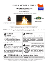
LOCATINg FIREBOx
PROduCT dIMENSIONS
41.16”
5”
5.50”
18”
18”
28.25
”
28.25”
31.25”
36”
11”
2”
8.15”
Gas Line Access, Both Sides
RIGHT SIDE VIEW
FRONT VIEW
TOP VIEW
41.16”
5”
5.50”
18”
18”
28.25
”
28.25”
31.25”
36”
11”
2”
8.15”
Gas Line Access, Both Sides
RIGHT SIDE VIEW
FRONT VIEW
TOP VIEW
41.16”
5”
5.25”
18”
18”
28.25
”
28.25”
31.25”
36”
11”
2”
8.15”
Gas Line Access, Both Sides
RIGHT SIDE VIEW
FRONT VIEW
TOP VIEW
AIR FOR COMBuSTION
ANd VENTILATION
Today’shomesarebuiltmoreenergyefcientthanever.New
materials, increased insulation, and new construction methods
help reduce heat loss in homes. Home owners weather strip
and caulk around windows and doors to keep the cold air out
and the warm air in. During heating months, home owners
want their homes as airtight as possible.
While it is good to make your home energy efficient, your
home needs to breathe. Fresh air must enter your home. All
fuel-burning appliances need fresh air for proper combus-
tion and ventilation.
Exhaust fans, fireplaces, clothes dryers, and fuel burning ap-
pliances draw air from the house to operate. You must provide
adequatefreshairfortheseappliances.Thiswillinsureproper
venting of vented fuel-burning appliances.
PROVIDING ADEQUATE
VENTILATION
The following are excerpts from National Fuel Gas Code
ANSI Z223.1/NFPA 54, Section 5.3, Air for Combustion
and Ventilation.
All spaces in homes fall into one of the three following
ventilation classifications:
1. Unusually Tight Construction
2. Unconfined Space
3. Confined Space
The information on pages 4 through 6 will help you classify
yourspaceandprovideadequateventilation.
WARNING: This heater shall not be
installed in a room or space unless the
required volume of indoor combustion air
is provided by the method described in
the National Fuel Gas Code, ANSI Z223.1/
NFPA 54, the International Fuel Gas Code,
or applicable local codes.
ELECTRICAL
There is a provided “J” box, accessible from either end of
the fireplace. Electrical connection should be made by a
qualiedinstaller.Followalllocalcodes.
Read the following instructions to insure
proper fresh air for this and other fuel-
burning appliances in your home.

5
Unusually Tight Construction
The air that leaks around doors and windows may provide
enough fresh air for combustion and ventilation. However, in
buildings of unusually tight construction, you must provide
additional fresh air.
Unusually tight construction is defined as con-
struction where:
a. walls and ceilings exposed to the outside
atmosphere have a continuous water vapor
retarder with a rating of one perm (6 x 10
-11
kg
per pa-sec-m
2
) or less with openings gasketed
or sealed and
b. weather stripping has been added on openable
windows and doors and
c. caulking or sealants are applied to areas such
as joints around window and door frames,
between sole plates and floors, between wall-
ceiling joints, between wall panels, at penetra-
tions for plumbing, electrical, and gas lines,
and at other openings.
If your home meets all of the three criteria above,
you must provide additional fresh air. See Ventila-
tion Air From Outdoors, page 5.
If your home does not meet all of the three criteria
above, proceed to Determining Fresh-Air Flow for
Fireplace Location, page 6.
Confined and Unconfined Space
The National Fuel Gas Code ANSI Z223.1/NFPA 54 defines
a confined space as a space whose volume is less than 50
cubic feet per 1,000 Btu per hour (4.8 m
3
per kw) of the
aggregate input rating of all appliances installed in that
space and an unconfined space as a space whose volume
is not less than 50 cubic feet per 1,000 Btu per hour (4.8
m
3
per kw) of the aggregate input rating of all appliances
installed in that space. Rooms communicating directly with
the space in which the appliances are installed*, through
openings not furnished with doors, are considered a part
of the unconfined space.
* Adjoining rooms are communicating only if there are
doorless passageways or ventilation grills between them.
VENTILATION AIR
Ventilation Air From Inside Building
This fresh air would come from an adjoining unconfined
space. When ventilating to an adjoining unconfined space,
you must provide two permanent openings: one within 12"
of the ceiling and one within 12" of the floor on the wall
connecting the two spaces (see Figure 1). You can also
remove door into adjoining room (see Figure 1). Follow
the National Fuel Gas Code ANSI Z223.1/NFPA 54, Sec-
tion 5.3, Air for Combustion and Ventilation
forrequired
size of ventilation grills or ducts.
Ventilation Air From Outdoors
Provide extra fresh air by using ventilation grills or ducts.
You must provide two permanent openings: one within
12" of the ceiling and one within 12" of the floor. Connect
these items directly to the outdoors or spaces open to the
outdoors. These spaces include attics and crawl spaces.
Follow the National Fuel Gas Code ANSI Z223.1/NFPA
54, Section 5.3, Air for Combustion and Ventilation for
requiredsizeofventilationgrillsorducts.
IMPORTANT: Do not provide openings for inlet or outlet
air into attic if attic has a thermostat-controlled power vent.
Heated air entering the attic will activate the power vent.
Or
Remove
Door into
Adjoining
Room,
Option
3
Ventilation Grills
Into Adjoining Room,
Option 2
Ventilation
Grills
Into Adjoining
Room,
Option 1
12"
12"
Figure 1 - Ventilation Air from Inside Building
Outlet
Air
Ventilated
Attic
Outlet
Air
Inlet
Air
Inlet Air
Ventilated
Crawl Space
To
Crawl
Space
To Attic
Figure 2 - Ventilation Air from Outdoors

6
DETERMINING FRESH-AIR FLOW
FOR FIREPLACE LOCATION
Determining if You Have a Confined
or Unconfined Space
Use this work sheet to determine if you have a confined
or unconfined space.
Space: Includes the room in which you will install fire-
place plus any adjoining rooms with doorless passageways
or ventilation grills between the rooms.
1. Determine the volume of the space (length x width x
height).
Length x Width x Height = cu. ft. (volume of space)
Example: Space size 22 ft. (length) x 18 ft. (width) x
8 ft. (ceiling height) = 3168 cu. ft. (volume of space)
If additional ventilation to adjoining room is supplied
with grills or openings, add the volume of these rooms
to the total volume of the space.
2. Multiply the space volume by 20 to determine the maxi-
mum Btu/Hr the space can support.
_______ (volume of space) x 20 = (Maximum Btu/Hr
the space can support)
Example: 3168 cu. ft. (volume of space) x 20 =
63,360
(maximum Btu/Hr the space can support)
3. Add the Btu/Hr of all fuel burning appliances in the
space.
Vent-free fireplace _____________ Btu/Hr
Gas water heater* ______________ Btu/Hr
Gas furnace ___________________ Btu/Hr
Vented gas heater ______________ Btu/Hr
Gas fireplace logs ______________ Btu/Hr
Other gas appliances* + ________ Btu/Hr
Total = ________ Btu/Hr
* Do not include direct-vent gas appliances. Direct-vent
draws combustion air from the outdoors and vents to
the outdoors.
Example:
Vent-free fireplace ____________ Btu/Hr
Gas water heater* _____________ Btu/Hr
Total = ________ Btu/Hr
4.
Compare the maximum Btu/Hr the space can support with
the actual amount of Btu/Hr used.
____ Btu/Hr (max. the space can support)
____ Btu/Hr (actual amt. of Btu/Hr used)
Example: 63,300 Btu/Hr (maximum the space can sup-
port)
73,000 Btu/Hr (actual amount of Btu/Hr used)
The space in the above example is a confined space because
the actual Btu/Hr used is more than the maximum Btu/Hr
the space can support. You must provide additional fresh
air. Your options are as follows:
A.
Rework work sheet, adding the space of an adjoining room.
If the extra space provides an unconfined space, remove
door to adjoining room or add ventilation grills between
rooms. See Ventilation Air from Inside Building, page 5.
B. Vent room directly to the outdoors. See Ventilation Air
from Outdoors, page 5.
C. Install a lower Btu/Hr fireplace, if lower Btu/Hr size
makes room unconfined.
If the actual Btu/Hr used is less than the maximum Btu/Hr
the space can support, the space is an unconfined space.
You will need no additional fresh air ventilation.
40,000
39,000
79,000
AIR FOR COMBuSTION
ANd VENTILATION
Continued
WARNING: If the area in which the
heater may be operated is smaller than that
defined as an unconfined space or if the
building is of unusually tight construction,
provide adequate combustion and ventila-
tion air by one of the methods described in
the National Fuel Gas Code, ANSI Z223.1/
NFPA 54, Air for Combustion and Ventila-
tion, or applicable local codes.

7
INSTALLATION
WARNING: A qualified service person
must install fireplace. Follow all local
codes.
WARNING: Never install the fireplace
• inabedroomorbathroom
• inarecreationalvehicle
• where curtains, furniture, clothing, or
other flammable objects are less than
42 inches from the front, top, or sides
of the fireplace
• inhightrafcareas
• inwindyordraftyareas
NOTICE: This appliance is intended for
supplemental heating. Use this heater
along with your primary heating system.
Do not install this heater as your primary
heat source. If you have a central heating
system, you may run system’s circulating
blower while using heater. This will help
circulate the heat throughout the house. In
the event of a power outage, you can use
this heater as your primary heat source.
CAUTION: This fireplace creates warm
air currents. These currents move heat to
wall surfaces next to fireplace. Installing
fireplace next to vinyl or cloth wall cover-
ings or operating fireplace where impurities
(such as tobacco smoke, aromatic candles,
cleaning fluids, oil or kerosene lamps, etc.)
in the air exist, may discolor walls.
Note: Your fireplace is designed to be used in zero clear-
ance installations. Wall or framing material can be placed
directly against any exterior surface on the rear, sides, or
top of your fireplace, except where standoff spacers are
integrally attached. If standoff spacers are attached to your
fireplace, these spacers can be placed directly against wall
or framing materials.
Use the dimensions shown for rough openings to create the easi-
est installation (see Built-In Fireplace Installation, page 8).
IMPORTANT: Vent-free heaters add moisture to the air.
Although this is beneficial, installing fireplace in rooms
without enough ventilation air may cause mildew to form
from too much moisture. See Air for Combustion and
Ventilation, page 4.
IMPORTANT: Make sure the fireplace is level. If fireplace
is not level, fireplace will not work properly.
WARNING: This appliance is equipped
for either natural or propane (LP) gas. Field
conversion is not permitted.
INSTALLATION CLEARANCES
WARNING: Maintain the minimum
clearances. If you can, provide greater
clearances from floor, ceiling, and adjoin-
ing wall.
Carefully follow the instructions below. This will ensure
safe installation.
Minimum Wall and Ceiling Clearances
A. Clearances from the side of the fireplace opening to any
combustible material and wall should follow diagram in
Figure 3.
Example: The face of a mantel, bookshelf, etc.
is made of combustible material and protrudes
3.5" from the wall. This combustible ma-
terial must be 4" from the side of the fireplace
cabinet (see Figure 3).
B. Clearances from the top of the fireplace opening to the
ceiling should not be less than 42 inches.
C. When the firebox is installed on carpeting or other com-
bustible material, other than wood flooring, the firebox
should be installed on a metal or wood panel extending
the full width and depth of the enclosure.
D. Clearances from the bottom of firebox to the floor is 0
inches.
Figure 3 - Minimum Clearance for Combustible to Wall
*Minimum 16 inches from Side Wall
Example
CAUTION: Do not install the firebox
directly on carpet or vinyl.
CHECK GAS TYPE
Use the correct gas type (natural or propane/LP) for your
fireplace. If your gas supply is not correct, do not install
fireplace. Call dealer where you bought fireplace for proper
type fireplace.

8
INSTALLING GAS PIPING TO
FIREPLACE LOCATION
WARNING: A qualified service person
must connect fireplace to gas supply. Fol-
low all local codes.
WARNING: Never connect natural gas
fireplace to private (non-utility) gas wells.
This gas is commonly known as wellhead
gas.
CAUTION: Never connect propane/LP
fireplace directly to the propane/LP supply.
This fireplace requires an external regulator
(not supplied). Install the external regula-
tor between the fireplace and propane/LP
supply.
Figure 5 - External Regulator with Vent Pointing Down
Propane/LP
Supply Tank
External
Regulator
Vent
Pointing
Down
Installation Items Needed
Before installing fireplace, make sure you have the items
listed below.
• externalregulatorforpropane/LPunitonly(suppliedby
installer)
• piping(checklocalcodes)
• sealant(resistanttopropane/LPgas)
• testgaugeconnection*
• sedimenttrap(optional)
• teejoint
• pipewrench
• approvedexiblegaslinewithgasconnector(ifallowed
by local codes) (not provided)
*ACSA/AGAdesign-certiedequipmentshutoffvalve
with 1/8" NPT tap is an acceptable alternative to test gauge
connection. Purchase the optional CSA/AGA design-certified
equipmentshutoffvalvefromyourdealer.
For propane/LP units, the installer must supply an external
regulator. The external regulator will reduce incoming
gas pressure. You must reduce incoming gas pressure to
between 11 and 13 inches of water. If you do not reduce
incoming gas pressure, heater regulator damage could oc-
cur. Install external regulator with the vent pointing down
as shown in Figure 5. Pointing the vent down protects it
from freezing rain or sleet.
WARNING: This appliance requires a
1/2" NPT (National Pipe Thread) inlet con-
nection to the pressure regulator.
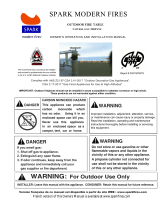
INSTALLATION
Continued
NOTICE: Surface temperatures of adjacent
walls and mantels become hot during
operation. Walls and mantels above the
firebox may become hot to the touch. If
installed properly, these temperatures meet
the requirement of the national product
standard. Follow all minimum clearances
shown in this manual.
0.50”
31.5”
VENT FREE FIRE
RIBBON FRAMING
DIMENSIONS
42”
Remote
Switch
Remote
Switch
28.25”
VENT FREE FIRE RIBBON
F A CING DIMENSIONS
MINIMUM NON-COMBUSTIBLE
MATERIALS
NON-COMBUSTIBLE
MATERIAL AREA
COMBUSTIBLE
MATERIAL
42”
Figure 4 - Installation Specifications
NOTICE: If installing on combustible floor-
ing other than wood (carpet, vinyl flooring,
vinyl tile, etc.), a metal or wood panel ex-
tending the full length and depth of the unit
must be installed under the fireplace.

9
CAUTION: Use only new, black iron or
steel pipe. Internally-tinned copper tubing
may be used in certain areas. Check your
local codes. Use pipe of 1/2" diameter
or greater to allow proper gas volume to
fireplace. If pipe is too small, undue loss
of pressure will occur.
Figure 6 - Gas Connection
*PurchasetheoptionalCSA/AGAdesign-certiedequipment
shutoff valve from your dealer.
** Minimum inlet pressure for purpose of input adjustment.
Installation must include an equipment shutoff valve,
union, and plugged 1/8" NPT tap. Locate NPT tap within
reach for test gauge hook up. NPT tap must be upstream
from fireplace.
CSA/AGA Design-
Certified Equipment
Shutoff Valve With
1/8" NPT Tap*
3" Minimum
Tee
Joint
Pipe
Nipple
Cap
Sediment
Trap
Approved
Flexible
Gas Line
NEW CONSTRUCTION
Remove the remote receiver from the heat shield inside
the fireplace access area. Route the wire extension cable
out the side of the fireplace to the best location for access
to the switch. There is a total of 9 feet (3 meters) of wire.
Mount the switch into an electrical box in an adjacent wall.
Be careful not to damage the wires.
EXISTING CONSTRUCTION
As an option, the remote receiver may be retained inside
the fireplace bottom. Battery access is better when located
in an adjacent wall.
SHUTOFF VALVE
IMPORTANT: Install equipment shutoff valve in
an accessible location. The equipment shutoff
valve is for turning on or shutting off the gas to
the appliance.
Check your building codes for any special re-
quirements for locating equipment shutoff valve
to fireplaces.
Apply pipe joint sealant lightly to male NPT threads. This
will prevent excess sealant from going into pipe. Excess
sealant in pipe could result in clogged fireplace valves.
Never use sealant on flare threads.
CAUTION: Use pipe joint sealant that is
resistant to liquid petroleum (LP) gas.
We recommend that you install a sediment trap in supply
line as shown in Figure 6. Locate sediment trap where it is
within reach for cleaning. Install in piping system between
fuel supply and fireplace. Locate sediment trap where
trapped matter is not likely to freeze. A sediment trap traps
moisture and contaminants. This keeps them from going
into fireplace gas controls. If sediment trap is not installed
or is installed wrong, fireplace may not run properly.
Figure 7 - Attaching Flexible Gas Lines Together
To Fireplace
Gas Regulator
Flexible Gas
Line from
Equipment
Shutoff Valve
Equipment
Shutoff Valve
➞
➞
To External
Regulator
NOTICE: Most building codes do not permit
concealed gas connections. A flexible gas
line is provided to allow accessibility from
the fireplace (see Figure 7). The flexible gas
supply line connection to the equipment
shutoff valve should be accessible.
CONNECTING FIREPLACE TO GAS
SUPPLY
1. Remove access panel.
2. Routegasline(providedbyinstaller)fromequipment
shutoff valve to fireplace. Route flexible gas supply line
through one of the access holes.
3. Attach the flexible gas line to gas supply as per Figure
7. Check tightness of flexible gas line attached to gas
regulator of fireplace and check all gas connections for
leaks (see Checking Gas Connections, page 10).

ON
POSITION
OFF
POSITION
GRH/OV 020MANUAL SHUT-OFF VALVE
10
Figure 8 - Equipment Shutoff Valve
Open
Closed
Equipment
Shutoff
Valve
Pressure Testing Gas Supply Piping
System
Test Pressures In Excess Of 1/2 PSI
(3.5 kPa)
1. Disconnect fireplace with its main gas valve (control
valve) and equipment shutoff valve from gas supply
pipping system. Pressures in excess of 1/2 psi will damage
fireplace gas regulator.
2. Capoffopenendofgaspipewhereequipmentshutoff
valve was connected.
3. Pressurize supply piping system by either opening
propane/LP supply tank valve for propane/LP gas or
opening main gas valve located on or near gas meter of
natural gas or using compressed air.
4. Check all joints of gas supply piping system. Apply
noncorrosive leak detection fluid to all joints. Bubbles
forming show a leak.
5. Correct all leaks at once.
6. Reconnectreplaceandequipmentshutoffvalvetogas
supply. Check reconnected fittings for leaks.
CHECKING GAS CONNECTIONS
WARNING: Test all gas piping and con-
nections, internal and external to unit, for
leaks after installing or servicing. Correct
all leaks at once.
WARNING: Never use an open flame
to check for a leak. Apply a mixture of liq-
uid soap and water to all joints. Bubbles
forming show a leak. Correct all leaks at
once.
CAUTION: Make sure external regula-
tor has been installed between propane/
LP supply and fireplace. See guidelines
under Connecting Fireplace to Gas Sup-
ply, page 9.
PRESSURE TESTING FIREPLACE
GAS CONNECTIONS
1. Openequipmentshutoffvalve(seeFigure8).
2. Open main gas valve located on or near gas meter for
natural gas or open propane/LP supply tank valve.
3. Make sure control knob of fireplace is in the OFF posi-
tion.
4. Checkalljointsfromequipmentshutoffvalvetogas
control valve. Apply noncorrosive leak detection fluid
to all joints. Bubbles forming show a leak.
5. Correct all leaks at once.
6. Light fireplace (see Operating Fireplace, page 11).
Check all other internal joints for leaks.
7. Turn off fireplace (see Turning Off The Appliance, page
11).
INSTALLATION
Continued
Test Pressures Equal To or Less Than 1/2
PSIG (3.5 kPa)
1. Closeequipmentshutoffvalve(seeFigure8).
2. Pressurize supply piping system by either opening
propane/LP supply tank valve for propane/LP gas or
opening main gas valve located on or near gas meter of
natural gas or using compressed air.
3. Checkalljointsfromgasmetertoequipmentshutoff
valvefornaturalgasorpropane/LPsupplytoequipment
shutoff valve for propane/LP. Apply noncorrosive leak
detection fluid to all joints. Bubbles forming show a
leak.
4. Correct all leaks at once.
Note: If fireplace is fully assembled, you must first remove
the floor tray and heat shield before checking gas connec-
tions. Refer to the illustrated parts list in this manual for
the floor tray and heat shield locations. Replace floor tray
and heat shield after checking gas connections.

11
OPERATINg FIREPLACE
FOR YOUR SAFETY
READ BEFORE
LIGHTING
WARNING: If you do not follow these
instructions exactly, a fire or explosion may
result causing property damage, personal
injury or loss of life.
A. This appliance is equipped with an ignition device
which automatically lights the pilot. Do Not try to
light the pilot by hand.
B. BEFORE LIGHTING smell all around the appli-
ance area for gas. Be sure to smell next to the floor
because some gas is heavier than air and will settle
on the floor.
WHAT TO DO IF YOU SMELL GAS
• Donottrytolightanyappliance.
• Donottouchanyelectricswitch;
do not
use any phone in your building.
• Immediatelycallyourgassupplierfromaneigh-
bor’s phone. Follow the gas supplier’s instruc-
tions.
• Ifyoucannotreachyourgassupplier,callthere
department.
C. Main gas valve in this appliance is not serviceable
and does not have any control knobs or switches to
operate. Do not remove heat shields covering the
valveandelectronicdevices;donottrytorepairor
modifythevalveasitmayresultinareorexplo-
sion.Callaqualiedservicetechnicianifyouhave
any safety concerns.
D. Do not use this appliance if any part has been under
water.Immediatelycallaqualiedservicetechni-
cian to inspect the appliance and to replace any part
of the control system and any gas control which has
been under water.
OPERATING
INSTRUCTIONS
1.
STOP!Readthesafetyinformation,startingonpage2.
2. Removeoortrayfromtheappliance(seeillustrated
parts list).
3. Turn off all electric power to the appliance. Unplug
DC adapter from the power outlet.
4. Do not attempt to light the pilot by hand.
5.
Lift and remove heat shield covering electronic com-
ponentsinsideoftheunit(seeillustratedpartslist).
6. Turn main shutoff valve counterclockwise to
the ON position.
7. Set remote receiver switch to OFF position.
Figure 9a - Remote Receiver Switch in OFF Position
REMOTEON OFF
PRG
REMOTEON OFF
PRG
8. Waitve (5) minutes toclear out any gas.Then
smellforgas,includingneartheoor.Ifyousmell
gas,STOP!Follow“B”inthesafetyinformation.
Ifyoudon’tsmellgas,gotothenextstep.
Note: Before applying any power supply to the DFC
board,pleaseverifythattheelectricalconnections
areinaccordancetoFigure24,page21.
9. Plug supplied DC adapter into 110V power outlet.
10. Connect the wire to the DC input plug at the unit.
11. Replace heat shield.
12.Locate remotereceivereitherinsidetheunit(see
illustratedpartslist),ormountedinadjacentwall.
Make sure that the remote receiver switch is in
“REMOTE”(middle)position.
13. Replace floor tray.
14.Iftheappliancewillnotoperate,followtheinstruc-
tions“ToTurnOffGasToAppliance”andcallyour
service technician or gas supplier.
Initializing the System for the First Time
1.
Set the remote receiver switch to the OFF position.
Figure 9b - Remote Receiver Switch in REMOTE
Position
Figure 9c - Remote Receiver Switch in OFF Position
REMOTEON OFF
PRG
2. Ifinstalled,setthepilotamemodeselectorswitch
to the IPI position.
3. Install 4 AA batteries into the battery holder and
verify the polarity indicated on the battery holder.
Connect the battery holder to the DFC’s main wir-
ing harness.

12
2. Ifnecessary,removeaccesspanelfromtheappliance
to access manual shutoff valve on gas line.
3. Turn the gas control manual valve clockwise
to the full OFF position.
4. Ifnecessary,replaceaccesspanel.
Proflame G-Fire System Operation
Initializing the System for the First Time
1. Install the 4 AA batteries into the receiver batter bay.
Note the polarity of the batteries and insert into the
batterybayasindicatedonthebatterycover(+/-).
2. Placethe3-positionsliderswitchintheREMOTE
position.
3. Insert the end of a paper clip into the hole marked
PRG on the receiver front cover. The receiver will
beep three times to indicate that it is ready to syn-
chronize with a transmitter.
4. Install the 3 AAA batteries in the transmitter battery
bay located on the base of the transmitter.
5. Press the ON button on the transmitter. The receiver
will beep four times to indicate the transmitter’s
command is accepted. The system is now initial-
ized.
Temperature Indication Display
1. With the system in the OFF position, press the
THERMOSTAT key and the MODE key at the same
time.
2. LookattheLCDscreenonthetransmittertoverify
that a °C or °F is visible to the right of the room
temperaturedisplay(seeFigure10).
Pilot Main
IPI/CPI Turn-On Command Fireplace
Switch Switch Name State
Opened, IPI Opened Turn-OFF Flames OFF
Opened, IPI Closed Turn-ON Pilot & Main
Burner Flames
ON
Closed, CPI Opened Pilot-ON Pilot Flame ON
Closed, CPI Closed Turn-ON Pilot & Main
Burner Flames
ON
Command Definitions
REMOTE CONTROL
OPERATION
WARNING: Make sure the remote receiver
switch is in the OFF position when you are away
from home for long periods of time. Heater may
come on automatically with remote receiver
switch in the “REMOTE” position.
CAUTION: Do not try to adjust heating
levels by using the equipment shutoff
valve.
4. ConnecttheAC/DCwalladaptertotheDFC’sDC-
jackconnectoronthemainwiringharnessandplug
it into the main power supply.
Setting the Appliance into Continuous Pilot
Ignition Mode
1. SettheIPI/CPIpilotmodeswitchtotheCPIposi-
tion(switchclosed).Atthatpointtheunitwillim-
mediately ignite the pilot flame. The pilot flame will
remain ON.
Note: Ifpilotdoesnotstaylit,contactaqualied
service person or gas supplier for repairs.
Turning ON the Appliance
1. Slide the remote receiver switch to the ON position.
This will allow the main burner to ignite.
Turning OFF the Appliance
1. Slide the remote receiver switch to the OFF position.
This will turn off the main burner.
Note: IftheContinuousPilotignitionmodeisselected,
the pilot flame will remain ON. To turn the pilot flame
completelyOFF,switchtheapplianceintoIntermittent
Pilotignition mode and set theIPI/CPI pilot mode
switchtotheIPIposition(switchopened).
Note: Youmayberunningthisheaterforthersttime
afterhookinguptogassupply.Ifso,thecontrolknob
may need to be pressed in for 30 seconds or more. This
will allow air to bleed from the gas system.
Figure 9d - Remote Receiver Switch in ON Position
REMOTEON OFF
PRG
TO TURN OFF GAS
TO APPLIANCE
1. Turn off all electric power to the appliance if service
is to be performed. Unplug DC adapter from the
power outlet.

13
Turning ON the Appliance
1. PresstheON/OFFbuttononthetransmitter.The
transmitter screen will display all active icons. The
receiver will command the DFC board to start the
ignitionprocess.Oncethepilotameislit,theDFC
board will open the main valve outlet and the main
burnerwillignite.Asingle“beep”fromthereceiver
willconrmthecommand.
Turning OFF the Appliance
1. PresstheON/OFFbuttononthetransmitter.The
transmitter LDC display will only show the room
temperatureandicon(seeFigure11).Thereceiver
disconnects and will command the DFC board to
turn off the burner. Depending upon the system
model (IPI orCPI), the pilot may shut off (IPI
model) or remain lit (CPI model) and the main
burnerturnsoff.Asingle“beep”fromthereceiver
willconrmthecommand.
Figure 10 - Remote Control Display in Farenxheit and
Celsius
Figure 11 - Remote Control Displaying Room
Temperature
2. Press the up-arrow key to increase the flame
height.
Note: If you press the up-arrow while the remote
systemisONbuttheameisOFF,theamewill
comeoninthehighposition.Asingle“beep”from
thereceiverwillconrmthecommand.
Figure 12 - Remote Control Displaying Flame Levels
Flame OFF
Flame Level 5
Flame Level 1
Flame Level Max.
Figure 13 - Remote Control Displaying Split Flow Mode
Flame Height Control
Proflame GT
1. With the system ON and the flame present in the
appliance,pressthedown-arrowkeytoturname
OFF.
2. Press the up-arrow key and the amewill turn
ON.
Proflame GTM & GTMF
Theseunitshavesixamelevels(seeFigure12).
1. With the system ON and the flame level at maximum
height,pressthedown-arrowkeyoncetoreducethe
flame height by one step. Continue pressing down-
arrow key until flame is turned OFF.
Set
Temperature
Room
Temperature
Figure 14 - Remote Control Displaying Room
Temperature and Set Temperature
Room Thermostat
(Transmitter Operation)
The remote control can operate as a room thermostat.
The thermostat can be set to a desired temperature to
control the comfort level in the room.
1. Toactivatethisfunction,presstheThermostatkey.
The LCD display on the transmitter will change to
show that the room thermostat is ON and the set
temperatureisnowdisplayed(seeFigure14).
2. Adjustthesettemperaturebypressingtheupor
down-arrow keys until the desired set temperature
isdisplayedontheLCDscreen(seeFigure14).

14
Manual Override
If the receiver or transmitter batteries are low or de-
pleted,theappliancecanstillbeturnedonmanually.
1. Move the receiver’s three-position slider to the ON
position. This will bypass the remote control feature
of the system and the appliance main burner will
turn on.
Figure 16 - Remote Control Displaying Key Lock
Mode
Figure 17 - Remote Control Displaying Low Battery
Key Lock
This function will lock the keys to avoid unsupervised
operation.
1. Toactivatethisfunction,presstheMODEandUP
keys at the same time. A lock icon will appear on the
LCDscreen(seeFigure16).
2. Todeactivatethisfunction,presstheMODEandUP
keys at the same time. The lock icon will disappear
from the LCD screen.
Low Battery Power Detection
Receiver
The life span of the receiver batteries depends upon
variousfactors:batteryquality,numberofapplianceig-
nitions,numberofthermostatsetpointchanges,etc.
When the receiver batteries are low, no “beep”will
sound from the receiver when a transmitter command
is sent. Replace batteries when this happens.
Transmitter
The life span of the transmitter batteries depends upon
variousfactors:batteryquality,numberofapplianceig-
nitions,numberofthermostatsetpointchanges,etc.
When the transmitterbatteries arelow, an icon will
appearontheLCD display (see Figure17).Replace
batteries when this icon appears.
Figure 15 - Remote Control Displaying Smart
Thermostat Function
Smart Thermostat
(Transmitter Operation- Proflame GTM, GTMF, &
GTMFS only)
TheSmartThermostatfunctionadjuststheameheight
in accordance to the difference between the set point
temperature and the actual room temperature. As the
roomtemperaturegetsclosertothesetpoint,theSmart
Function will modulate the flame down.
1. Toactivatethisfunction,presstheThermostatkey
untiltheword“SMART”appearstotherightofthe
temperaturebulbontheLCDscreen (see Figure
15).
2. To adjust the set temperature, press the up or
down-arrow keys until the desired set temperature
is displayed on the LCD screen.

15
Pilot IPI/CPI Receiver Slider Command Fireplace
Switch Position Name State
Opened, IPI Turn-OFF Flames OFF
Opened, IPI Turn-ON Pilot & Main
Burner Flames
ON
Closed, CPI Pilot-ON Pilot Flame ON
Closed, CPI Turn-ON Pilot & Main
Burner Flames
ON
“OFF”
“ON”
“OFF”
“ON”
“REMOTE”
& “OFF received”
“REMOTE”
& “ON received”
“REMOTE”
& “OFF received”
“REMOTE”
& “ON received”
Command Definitions
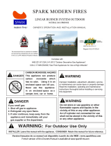
Check pilot flame pattern and burner flame patterns often.
PILOT FLAME PATTERN
Figure 18 shows a correct pilot flame pattern. Figure 19
shows an incorrect pilot flame pattern. The incorrect pilot
flame is not touching the flame sensor. This will cause the
flame sensor to cool. When the flame sensor cools, the
fireplace will shut down.
If pilot flame pattern is incorrect, as shown in Figure 19
•
turn fireplace off (see Turning OFF The Appliance, page 11)
•
see Cleaning and Maintenance, page 16
Note: The correct pilot flame on natural gas units will have
a slight curve, but flame should be blue and have no yellow
or orange color.
Figure 21 - Incorrect Front Burner Flame Pattern
Showing Solid Yellow/Orange Flame
Figure 20 - Correct Front Burner Flame Pattern
Showing Blue Flame with Yellow/White Tips
Figure 18 - Correct Pilot Flame Pattern
Pilot Burner
Figure 19 - Incorrect Pilot Flame Pattern
INSPECTINg BuRNERS
MAIN BURNER
Periodically inspect all burner flame holes with the fireplace
running. Some burner flame holes may become blocked
by debris or rust, with no flame present. If so, turn off
fireplace and let cool. Remove blockage. Blocked burner
flame holes may create soot.
FRONT BURNER FLAME PATTERN
Figure 20 shows correct front burner flame pattern. Figure 21
shows incorrect front burner flame pattern. The correct burner
flame pattern shows yellow tipping at top of blue flame.
If front burner flame pattern is incorrect, as shown in
Figure 21
•
turn fireplace off (see Turning OFF The Appliance, page 11)
•
see Troubleshooting, page 17
Flame Sensor
Pilot Burner
Flame Sensor

16
CLEANINg ANd
MAINTENANCE
WARNING: Turn off fireplace and let cool
before cleaning.
CAUTION: Keep burner and control
compartment clean. See installation and
operating instructions accompanying
heater. Inspect these areas of fireplace
before each use. Have fireplace inspected
yearly by a qualified service person. Fire-
place may need more frequent cleaning due
to excessive lint from carpeting, bedding
material, pet hair, etc.
WARNING: Failure to keep the primary
air opening of the burner clean may result
in sooting and property damage.
BURNER INJECTOR HOLDER AND
PILOT AIR INLET HOLE
The primary air inlet holes allow the proper amount of air
to mix with the gas. This provides a clean burning flame.
Keep these holes clear of dust, dirt, lint, and pet hair. Clean
these air inlet holes prior to each heating season. Blocked
air holes will create soot. We recommend that you clean the
unit every three months during operation and have heater
inspectedyearlybyaqualiedserviceperson.
We also recommend that you keep the burner tube and pilot
assembly clean and free of dust and dirt. To clean these
parts we recommend using compressed air no greater than
30 PSI. Your local computer store, hardware store, or home
center may carry compressed air in a can. You can use a
vacuum cleaner in the blow position. If using compressed
air in a can, please follow the directions on the can. If you
don't follow directions on the can, you could damage the
pilot assembly.
1. Shut off the unit, including the pilot. Allow the unit to
cool for at least thirty minutes.
2.
Inspect burner, pilot, and primary air inlet holes on injector
holder for dust and dirt (see Figure 22).
3. Blow air through the ports and holes in the burner.
4. Check the injector holder located at the end of the burner
tube again. Remove any large particles of dust, dirt, lint, or
pet hair with a soft cloth or vacuum cleaner nozzle.
5. Blow air into the primary air holes on the injector
holder.
Figure 22 - Injector Holder On Outlet Burner Tube
6. In case any large clumps of dust have now been pushed
into the burner repeat steps 3 and 4.
Clean the pilot assembly also. A yellow tip on the pilot
flame indicates dust and dirt in the pilot assembly. There
is a small pilot air inlet hole about two inches from where
the pilot flame comes out of the pilot assembly (see Figure
23). With the unit off, lightly blow air through the air inlet
hole. You may blow through a drinking straw if compressed
air is not available.
Figure 23 - Pilot Inlet Air Hole
Pilot
Assembly
Pilot Air
Inlet Hole
Burner
Tube
Ports/Slots
Replace any screen or guard (heat shield
or cover), before operating appliance.

17
TROUBLESHOOTING
WARNING: Turn off heater and let cool before servic-
ing. Only a qualified service person should service and
repair heater.
Help is available by emailing to info@sparkfires.com
or calling 866-938-3846.
CAUTION: Never use a wire, needle, or similar object
to clean ODS/pilot. This can damage ODS/pilot unit.
POSSIBLE CAUSE
1. Ignitor electrode not con-
nected to ignitor cable
2. Ignitor cable pinched or
wet
3. Broken ignitor cable
4. Bad ignitor
5. Ignitor electrode broken
6. Ignitor electrode positioned
wrong
1. Gas supply turned off or
equipmentshutoffvalve
closed
2. Air in gas lines when
installed
3. Depleted gas supply
4. ODS/pilot is clogged
5. Gas regulator setting is not
correct
REMEDY
1. Reconnect ignitor cable
2.
Free ignitor cable if pinched
by any metal or tubing.
Keep ignitor cable dry
3. Replace ignitor cable
4. Call for service
5. Replace pilot assembly
6. Replace pilot assembly
1. Turn on gas supply or open
equipmentshutoffvalve
2. Continue holding down
control knob. Repeat ignit-
ing operation until air is
removed
3. Contact local propane/LP
gas company
4. Clean ODS/pilot (see
Cleaning and Maintenance,
page 16) or replace ODS/
pilot assembly
5. Replace gas control
OBSERVED PROBLEM
When remote button is pressed,
there is no spark at ODS/pilot
When remote button is pressed,
there is spark at ODS/pilot but
no ignition
Note: All troubleshooting items are listed in order of operation.
Pilot light stays on when main
burner is turned OFF
1. Switch in wiring harness
set to wrong position
2. IPI/CPI switch in wrong
position
1. Change switch position
2. Check toggle switch in wir-
ing harness marked CPI/IPI.
Make sure switch is in IPI
position

18
OBSERVED PROBLEM
ODS/pilot lights but flame
goes out
Burner does not light after
ODS/pilot is lit
Delayed ignition burner
POSSIBLE CAUSE
1. Equipmentshutoffvalve
not fully open
2. Pilot flame not touching
flame sensor, which al-
lows flame sensor to cool,
causing pilot flame to go
out. This problem could be
caused by one or both of
the following:
A) Low gas pressure
B)
Dirty or partially clogged
ODS/pilot
3. Flame sensor connection
loose at control valve
4. Flame sensor damaged
5. Control valve damaged
6. Safety interlock system has
been triggered
1. Inlet gas pressure is too
low
2. Burner orifice clogged
3. Thermopile leads discon-
nected or improperly con-
nected
4. Burners will not come on
in remote position
5. Wire disconnected from
gas control
1. Manifold pressure is too
low
2. Burner orifice clogged
REMEDY
1. Fullyopenequipmentshut-
off valve
2. A) Contact local propane/LP
gas company
B) Clean ODS/pilot (see
Cleaning and Maintenance,
page 16) or replace ODS/
pilot assembly
3. Hand tighten until snug,
then tighten 1/4 turn more
4. Replace pilot assembly
5. Replace control valve
6. Wait one minute for safety
interlock system to reset.
Repeat ignition operation.
1. Contact local natural or
propane/LP gas company
2. Clean burner (see Cleaning
and Maintenance, page 16)
or replace burner orifice
3. Reconnect leads (see Wiring
Diagram, page 21)
4. Replace battery in transmit-
ter and receiver
5. Reconnect wire (see Wiring
Diagram, page 21)
1. Contact local natural or
propane/LP gas company
2. Clean burner (see Cleaning
and Maintenance, page 16)
or replace burner orifice
TROUBLESHOOTING
continued

19
TROUBLESHOOTING
continued
OBSERVED PROBLEM
Burner backfiring during
combustion
Slight smoke or odor during
initial operation
Moisture/condensation no-
ticed on windows
Heater produces a whistling
noise when burner is lit
White powder residue form-
ing within burner box or on
adjacent walls or furniture
Remote does not function
REMEDY
1. Clean burner (see Cleaning
and Maintenance, page 16)
or replace burner orifice
2. Replace damaged burner
3. Replace gas regulator
1. Problem will stop after a
few hours of operation
2. Check burner for dirt and
debris. If found, clean
burner (see Cleaning and
Maintenance, page 16)
3. Replace gas control
1. Refer to Air for Combustion
and Ventilationrequire-
ments (page 4)
1. Turn control knob to LO
position and let warm up for
a minute
2. Operate burners until air is
removed from line. Have
gas line checked by local
natural or propane/LP gas
company
3.
Observe minimum installa-
tion clearances (see pages 8)
4. Clean burner (see Cleaning
and Maintenance, page 16)
or replace burner orifice
1. Turn heater off when using
furniture polish, wax, clean-
ers, or similar products
1. See instructions on page 14,
Key Lock
2. Replace batteries in receiver
and remote control
POSSIBLE CAUSE
1. Burner orifice is clogged or
damaged
2. Damaged burner
3. Gas regulator defective
1. Residues from manufactur-
ing processes
2. Not enough air
3. Gas regulator defective
1. Not enough combustion/
ventilation air
1. Advance control to HI
position when burner
is cold
2. Air in gas line
3. Air passageways on heater
blocked
4. Dirty or partially clogged
burner orifice
1. When heated, vapors from
furniture polish, wax, car-
pet cleaners, etc. turn into
white powder residue
1. Remote is “locked”
2. Battery is not installed.
Battery power is low

20
OBSERVED PROBLEM
Fireplace produces a clicking/
ticking noise just after burners
are lit or shut off
Fireplace produces unwanted
odors
Fireplace shuts off in use
(ODS operates)
Gas odor even when control
knob is in OFF position
Gas odor during combustion
REMEDY
1. This is common with
most fireplaces. If noise is
excessive,contactqualied
service person
1. Open window and ventilate
room. Stop using odor caus-
ing products while fireplace
is running
2. Refill supply tank (propane/
LP gas only)
3. Locate and correct all leaks
(see Checking Gas Connec-
tions, page 10)
1. Open window and/or door
for ventilation
2. Contact local natural or
propane/LP gas company
3. Clean ODS/pilot (see
Cleaning and Maintenance,
page 16)
1. Locate and correct all leaks
(see Checking Gas Connec-
tions, page 10)
2. Replace control valve or gas
control
1. Take apart gas tubing and
remove foreign matter
2. Locate and correct all leaks
(see Checking Gas Connec-
tions, page 10)
POSSIBLE CAUSE
1. Metal expanding while
heating or contracting
while cooling
1.
Fireplace burning vapors
from paint, hair spray,
glues, cleaners, chemicals,
new carpet, etc. (see IM-
PORTANT statement above)
2. Low fuel supply (propane/
LP gas only)
3. Gas leak. See Warning
statement at top of
page
1. Not enough fresh air is
available
2. Low line pressure
3. ODS/pilot is partially
clogged
1. Gas leak. See Warning
statement at top of
page
2. Control valve or gas con-
trol defective
1. Foreign matter between
control valve and burner
2. Gas leak. See Warning
statement at top of
page
WARNING: If you smell gas
• Shutoffgassupply.
• Donottrytolightanyappliance.
• Do not touch any electrical switch; do not use any
phone in your building.
• Immediatelycallyourgassupplierfromaneighbor’s
phone. Follow the gas supplier’s instructions.
• If you cannot reach your gas supplier, call the re
department.
IMPORTANT: Operating fireplace where impurities in air exist may create
odors. Cleaning supplies, paint, paint remover, cigarette smoke, cements and
glues, new carpet or textiles, etc., create fumes. These fumes may mix with
combustion air and create odors. These odors will disappear over time.
TROUBLESHOOTING
continued
/