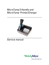
Maico MI 24 Operating Instructions Manual

Category
Measuring, testing & control
Type
Operating Instructions Manual

This manual is also suitable for

MAICO Diagnostics | 10393 West 70
th
Street | Eden Prairie, MN 55344, USA | Toll Free 888.941.4201
MI 24, MI 24h
Operating Instructions
Operating Instructions MI 24, MI 24h
i
Table of Contents Page
1. Introduction 1
2. Description 2
3. Getting started 4
4. How to create a tympanogram 12
5. How to create a tympanogram with high probe tone (MI 24h) 17
6. How to measure the Stapedius reflex 18
7. Interpreting test results 23
8. How to test children 26
9. Additional Reading 27
10. Individual setup of the MI 24 28
11. Care and maintenance of the instrument 33
12. How to change the printer paper 34
13. Warranty, maintenance and after-sales service 35
14. Safety regulations 38
15. Subjective checklist 39
16. Technical data 40
Operating Instructions MI 24, MI 24h
1
1 Introduction
Thank you very much for purchasing a quality product from the family. This
automatic Tympanometer MI 24 is manufactured to meet all quality and safety
requirements.
This user manual should make it as easy as possible for you to become familiar
with the functions of the MI 24. The description of the position (e.g., ) of
controls, displays and connections, found again in the text, will make it easier
for you to learn how to operate the MI 24.
If you have problems or have ideas for further improvements, please get in
touch with us. Simply call.
Your MAICO team
5
Operating Instructions MI 24, MI 24h
2
2 Description
The MI 24 is an automatic instrument that is designed for tympanometric screening.
Tests done in the tympanometric screening mode measure middle ear mobility and
ipsilateral acoustic reflex. Contralateral acoustic reflex is available as an option. Test
results are displayed on the front panel LCD (liquid crystal display) screen and may be
printed.
The design of the MI 24 allows rapid and reliable measurements. This equipment is
designed for middle ear function screening.
PC-Interface:
A USB interface for data transfer to a connected computer is built in.
2.1 Tympanometry
Tympanometry is the objective
measurement of middle ear
mobility (compliance) and pressure
within the middle ear system.
During the test, a low-pitched
probe tone (226 Hz) is presented to
the ear canal by means of the
hand-held probe. This tone is used
to measure the change in
compliance in the middle ear
system while the air pressure is
varied automatically from a positive
value (+200 daPa) to a negative
value (-400 daPa max.).
Maximum compliance of the middle ear system occurs when the pressure in the
middle ear cavity is equal to the pressure in the external auditory canal. This is the
highest peak of the curve as it is recorded on the chart. The position of the peak on
the horizontal axis and on the vertical axis of the chart will provide diagnostic
information regarding the function of the middle ear system. Examples of normal and
abnormal tympanograms can be found in a later section of this manual.
Gradient calculations are reported as the tympanogram width at half of peak
compliance expressed in daPa. A “limits” box is available on both the display and
printout to aid in diagnosis.
Compliance is measured with respect to an equivalent volume of air, with the
scientific quantity milliliter (ml). Air pressure is measured in deca-Pascals (daPa).
hearing
nerve
ear canal
middle
ear
bones
ear drum
middle ear
eustachian tube
cochlea
musculus
stapedius
Figure 1
The middle ear
Operating Instructions MI 24, MI 24h
3
NOTE: 1.02 mm H
2
O = 1.0 daPa.
Operating Instructions MI 24, MI 24h
4
2.2 Acoustic Reflex
An acoustic reflex, or contraction of the Stapedial muscle, occurs under normal
conditions when a sufficiently intense sound is presented to the auditory pathway.
This contraction of the muscle causes a stiffening of the ossicular chain which
changes the compliance of the middle ear system. As in tympanometry, a probe tone
is used to measure this change in compliance.
When the stimulus presentation and measurement are made in the same ear by
means of the probe, this acoustical reflex is referred to as an ipsilateral acoustic
reflex. When the stimulus presentation and measurement are made in opposite ears,
the reflex is referred to as a contralateral acoustic reflex.
For best results, this reflex measurement is automatically conducted at the air
pressure value where the compliance peak occurred during the tympanometric test.
Stimulus tones of varying intensities at 500, 1000, 2000 or 4000 Hz are presented as
short bursts. If a change in compliance greater than 0.05 ml is detected, a reflex is
considered present. Because this is an extremely small compliance change, any
movement of the probe during the test may produce an artifact (false response). The
test result is recorded as Pass/No Response
,
and in graphical form.
If the tympanometric results display any abnormal findings, the results of the acoustic
reflex testing may be inconclusive and should be interpreted with care. Theoretically,
a compliance peak is necessary to observe a reflex at peak pressure.
Operating Instructions MI 24, MI 24h
5
3 Getting started
Your MI 24 was carefully inspected and packed for shipping. However, it is good
practice to thoroughly inspect the outside of the shipping container for signs of
damage. If any damage is noted, please notify the carrier immediately.
3.1 Unpacking
Remove the accessories. Carefully remove the instrument from the shipping carton.
Remove the instrument from the plastic bag and inspect the case for any damage.
Notify the carrier immediately if any mechanical damage is noted. This will assure that
a proper claim is made. Save all packing material so the claim adjuster can inspect it
as well. When the adjuster has completed the inspection, notify the MAICO Special
Instrument Distributor you purchased this unit from.
Save all the original packing material and the shipping container so the
instrument can be properly packaged if it needs to be returned for service or
calibration.
3.1.1 Accessories Supplied
Please check that all accessories listed below are received in good condition. If any
accessories are missing or damaged, immediately notify your MAICO Special
Instrument Distributor.
Description Part No.
Hand-held probe 570G-14
24-count eartips kit: 6613
(4) yellow, 7 mm 6643
(4) green, 9 mm 6644
(4) white, 11 mm 6645
(4) yellow, 13 mm 6646
(4) green, 15 mm 6647
(4) blue, 18 mm 6648
Thermal printer paper 5529
Calibration test cavity 5533
Operating Instructions 1162-0321
Optional Accessories:
Soft-sided carrying case 1035-3002
Contra button phone and cable 4796
Contra TDH 39 phone and cable 4682
Operating Instructions MI 24, MI 24h
6
Operating Instructions MI 24, MI 24h
7
3.2 Environmental conditions for the MI 24
The MI 24 should be operated in a quiet room.
The test room must be at normal temperature, usually 15° C / 59° F to 35° C / 95° F,
and the instrument should be switched on about 10 minutes before the first
measurement to guarantee precise measuring results. If the device has been cooled
down (e.g. during transport), please wait until it has warmed up to room
temperature
3.3 Preparing the MI 24 for use
3.3.1 Connect probe and accessories
- Connect the probe cable to socket on the rear of
the instrument.
- Insert the plug into the socket and secure the
connection by fastening the two screws of the
connector.
- Insert the pressure tube into the socket and press
it until it is secure on the socket.
- Put the enclosed power cable into the power
connection socket and then plug it into a power
outlet. The instrument is now operational.
Figure 2
The probe of the MI 24
C
B
A
Operating Instructions MI 24, MI 24h
8
3.4 Getting familiar with the MI 24
3.4.1 The MI 24 Front Panel Controls
See the following keys:
1. PRINT = Printout
2. L/R = Switch over left/right ear
3. REFLEX = Reflex measure off/ipsi/contra
4. MENU
5. LEFT = Left (cursor control)
6. DOWN = Down (cursor control)
7. RIGHT = Right (cursor control)
8. UP = Up (cursor control)
9. ENTER = Enter
10. POWER = Power switch
How to use the extended functions is described in chapter 9: “Individual Setup of the MI
Figure 3
The controls of the MI 24
Operating Instructions MI 24, MI 24h
9
24."
Operating Instructions MI 24, MI 24h
10
3.4.2 The MI 24 Rear Panel Connections
A. Power connection socket
B. Probe tube connection
C. Probe connection socket
D. PC interface
E. Contra receiver socket
3.4.3 Switch the instrument on
Turn the power switch on. The LCD will show the type of instrument and
software version for a moment. Then the basic measuring figure appears.
The MI 24 should be switched on about 10 minutes before the first measurement to
guarantee precise measuring results. If the device has been cooled down (e.g. during
transport), please wait until it has warmed up to room temperature.
10
B
E
C
A
D
Figure 4
Connectors on the rear of the MI 24
Operating Instructions MI 24, MI 24h
11
3.4.4 The display of the MI 24
The test result is shown during the measurement on the LCD. The measurements are
saved automatically and can be printed out in a fast and quiet way with the
integrated printer.
In figure 5 the initial empty
measurement screen is shown.
The measurement screen shows
actual settings, test results and
the graphical display of the
tympanogram and reflexes.
From left to right the top line
shows the type of test
(impedance is shown in Figure 5)
the selected test ear (left or right)
and the selected reflex test (
ipsi
,
contra
(optional) or
tympanogram
if no reflex test is
selected).
At the left center, the graph of
the tympanogram is shown. At the right, five boxes show the status and test values.
The upper box shows the actual status of the instrument:
READY - means that the instrument is ready for testing
IN EAR - shows that the probe is inserted in the ear
TESTING - means that the test is in progress
BLOCKED - means that probe is blocked in the ear
LEAKING - indicates that the ear tip does not have a proper seal
The boxes below Status show the volume of the ear canal, the compliance, the
pressure at maximum compliance and the gradient of the tympanogram when the
test has been completed.
The four boxes at the bottom of the screen, marked 1 to 4, show the graphical reflex
curves after the test. Below each box the test level (Figure 5: 80 dB), and the test
frequencies (Figure 5: 500 Hz, 1000 Hz, 2000 Hz and 4000 Hz) are displayed. After
the frequency an “I” shows that ipsilateral testing is selected.
Finally, at the very bottom in (Figure 5) the word Auto and 80 dB scale is shown. This
means that the reflex test level will increase automatically until a reflex is found or the
maximum level is reached. With the arrow keys, the test levels can be changed to a
fixed level. The dB values below the boxes change accordingly. It is possible to have
fixed levels from 70 dB to 100 dB or Auto.
Status
READY
Ear Volume
Compliance
Pressure
Gradient
Impedance IpsiRight
ml
3
2
1
0
-600 -300 300 daPa
1
80
500 Hz I
4
80
4000 Hz I
3
80
2000 Hz I
2
80
1000 Hz I
AUTO dB
Figure 5
The measurement screen of the MI 24
Operating Instructions MI 24, MI 24h
12
3.5 Calibrate the probe
Adjust the impedance measuring instrument
every day to the actual atmospheric
pressure by means of the enclosed
calibration volume. The calibration is very
easy and takes only 20 seconds.
Press the menu key and the main menu
(Figure 6) appears on the LCD. Select the
menu option Calibration with the arrow
keys and press Enter
.
Follow the instructions
on the LCD as shown in figure 7.
Put the probe tip without ear tip into
the hole of the test cavity labeled 0.5 ml.
The text on the display will request that the
probe tip be inserted for the 2 ml
calibration. Put the probe tip in the 2 ml
cavity. Do this again for the 5 ml volume.
The MI 24 will automatically change into
the tympanometry mode. The basic menu
for the impedance measurement appears
again and you are ready for measurements.
If the error information Cavity Calibration
Out of Range appears during the
calibration, please check if the opening of
the probe tip is clean and try to recalibrate
the probe. If the error information appears
again, the probe or the instrument are
probably in need of service. Inform your
Maico Special Instrument Distributor to get
immediate help.
Main Menu
Tympanometry :
Calibration :
Setup :
Change item
ENTER Select item
Figure 6
The MI 24 main menu
Figure 7
The calibration screen
Calibration
Place the probe in the .5 ml cavity.
4
S
Operating Instructions MI 24, MI 24h
13
3.6 Getting familiar with the probe
The probe of the MI 24 is shown in figure 8. The probe head is adjustable to three
angles (0°, 60° and 80°). It is adjusted by turning the locking screw at the bottom
of the probe using a coin or a screw driver.
Adjust the probe head by pulling it into the required position until it rests. After
it is set to the required position tighten the fixation screw again.
The probe button can be
used to select the required
test ear.
The color of the control
light changes accordingly to
red (right ear) or blue (left
ear).
The color of the control light
on the probe indicates your
current operation.
A red control light indicates
that the right ear is selected.
The system is ready for
measurements. As soon as
you have put the probe into
the auditory canal the control light turns green. Now the test is in progress. Do not
change the position of the probe until the green control light goes out indicating the
end of the measurement.
A blue control light indicates that the left ear is selected. The system is ready for
measurements. As soon as you have put the probe into the auditory canal the control
light turns green. Now the test is in progress. Do not change the position of the
probe until the green control light goes out indicating the end of the measurement.
A yellow control light indicates an error. The kind of the error is indicated on the LCD
under status:
LEAKING: The ear tip is not sealed in the auditory canal. Change the position of the
probe until the control light turns green. If you are not successful use a
bigger ear tip.
BLOCKED: Indicates blockage in the probe opening. Change the position of the
probe so that it points straight into the auditory canal until the control
light turns green. If you are not successful, check that the probe is not
blocked with ear wax.
The complete probe insert can be changed by pressing the release button . and removing the probe insert.
T
P
M
O
Q
R
B D
C
E G
M O
N R SEQEPEL
Figure 8
The probe of the MI 24
D
C E G
T
N R SEPEL
Operating Instructions MI 24, MI 24h
14
If the probe tip is clogged, you can remove it by opening the fixation ring . After
cleaning the probe tip or attaching a new one, the tip must be fixed again by
fastening the fixation ring.
3.7 Choose an appropriate ear tip
Choose an ear tip of the appropriate size from the ear tip set. Put the ear tip tightly
on the probe tip. The probe tip should end near the end of the ear tip. It should not
be inserted more than about 1 mm inside the ear tip or just protrude out of the ear
tip (see Figure 9).
By choosing an appropriate ear tip and placing it correctly on the probe you create
the basic conditions for measurements without problems and mistakes.
Now all preparations are concluded and you can start the impedance and reflex
measurement. Please read the following chapters.
min 0 mm
max 1 mm
Figure 9
Proper placement
of ear tip
Operating Instructions MI 24, MI 24h
15
4 How to create a tympanogram
In the following paragraph we will briefly explain the principle and the background of
the impedance measurement to create a better understanding. If you want to begin
the measurements immediately, just skip this paragraph and continue reading section
4.3 “Preparing the Measurements.”
4.1 The basics of the impedance measurement
The impedance measurement assists
in diagnosing of the condition of the
middle ear and can therefore not be
compared directly with other
audiometric tests such as sound or
speech audiometry which assists in
the measurement of hearing.
Furthermore the impedance
measurement is an objective
measuring method which does not
depend on the cooperation of the
test person and can therefore not be
falsified by the patient.
The two most important impedance
measuring methods possible with
your MI 24 are tympanometry and
the measurement of the Stapedius
reflex which is discussed in chapter 5:
“How to measure the Stapedius
reflex.
hearing
nerve
ear canal
middle
ear
bones
ear drum
middle ear
eustachian tube
cochlea
musculus
stapedius
Figure 10
The middle ear
Figure 11
Principle of the impedance measurement
Operating Instructions MI 24, MI 24h
16
The impedance measurement examines the acoustic resistance of the middle ear. If
the eardrum is hit by a sound, part of the sound is absorbed and sent via middle ear
to the inner ear while the other part of the sound is reflected. The stiffer the eardrum
is the more sound is reflected and the less sound reaches the inner ear. Inside the
probe of the impedance measuring instrument a small loudspeaker is installed which
emits a low frequency sound through a tube (Figure 11: A) into the auditory canal
before the eardrum. Another tube (Figure 11: B) is connected to the microphone
inside the probe which receives the sound. Together with a third tube (Figure 11: C),
all three are inserted nearly to the eardrum and are made airtight against outside
pressure by the ear tip. A manometer and a pump, which can produce both positive
and negative pressure, are connected with tube C. Less sound is reflected to the
microphone when the eardrum is stiff and the eardrum transmits the majority of the
sound via the middle ear to the inner ear. The highest compliance is normally reached
with an air pressure corresponding to the outside pressure.
When performing tympanometry during a
measurement, a continuous change of
positive and negative pressure is produced
by the pump of the instrument in the
outer auditory canal. The compliance is
measured simultaneously and shown in a
diagram (the tympanogram) which
illustrates the compliance in ml over the
pressure in daPa. In Figure 12), the area
for normal tympanogram curves is
hatched. Here you can see that the
highest compliance is reached with
normal pressure. When you create
positive and negative pressure the
eardrum stiffens - the compliance
decreases.
So you can draw conclusions on the
condition of the middle ear from the form and the values of the tympanogram.
-300 -200 -100 0 +100
Pressure ( daPa )
1,2
2,0
1,6
0,8
0,4
0
Compliance ( ml)
Figure 12
Tympanogram
(normal curve area is hatched)
2.0
1.6
1.2
0.8
0.4
0
Operating Instructions MI 24, MI 24h
17
4.2 Preparing the patient
Explain to the patient that the measurement is painless and that nothing enters the
auditory canal. The patient does not have to respond when there are loud test
sounds or when the pressure in the auditory canal changes. In no case should the
patient swallow, chew or move during the measurement.
4.3 Preparing the measurement
The LCD shows the empty measurement screen for the right ear and the control light
of the probe turns red. To measure the left ear, change the side by pressing the L/R
key or the probe button . Then the selected test ear shown in the middle-top of
the LCD will change from Right
to Left and the control light of the probe will turn
blue. Switch off the reflex measurement by pressing the Reflex key .
The word Tympanometry must appear at the right top of the display. Make sure the
auditory canal is clear. Choose an ear tip according to the size of the auditory canal
and put it firmly onto the probe tip (see figure 9 in chapter 3.7).
4.4 Measuring the tympanogram
Take hold of the top of the outer ear and pull it back. Insert the probe with the ear
tip into the auditory canal until
the control light of the probe is
green indicating the start of the
test. Do not move the probe until
the green light goes out; the
patient must not swallow or
speak during the measurement.
During the test the LCD will
display the tympanogram on the
left side as the test is running
and then the values will appear
on the right side. After about 4-5
seconds the test is completed
and the green light turns off.
Now you can remove the probe
from the ear.
If an error occurs during the measurement the test will stop. If leakage occurs, the
control light of the probe turns yellow and Leaking will appear under Status. If the
probe is blocked, the control light of the probe turns yellow and Blocked will appear
under Status. Please proceed as described in chapter 3.6 Getting familiar with the
probe. To measure the other ear, change the side by pressing the L/R key or the
probe buttonand repeat the measuring procedure described above with the other
ear.
Status
READY
Ear Volume
Compliance
Pressure
Gradient
Impedance TympanometerRight
ml
3
2
1
0
-600 -300 300 daPa
Scale
Figure 13
Measurement screen (only tympanogram)
M
3
Operating Instructions MI 24, MI 24h
18
4.5 How to evaluate the tympanogram display
After having completed a
measurement you can see the
results on the LCD.
On the left side of the display
you see a graph of the
tympanogram. The area
surrounded by the box is valid
for “normal” tympanograms.
You can change the area or turn
it off.
For details see chapter 10
“Individual Setup of the MI 24.”
In the top-middle of the LCD,
the words Right or Left indicate
the ear chosen at the moment.
Tympanometer (at the top right) - indicates that the reflex measurement has been
switched off.
In the boxes to the right the following test measurements are displayed:
Ear Volume - indicates the volume of the section of the auditory canal between the
ear tip and the eardrum in ml (in the example 0.94 ml).
Compliance - indicates the maximum value of the compliance from the
tympanogram in ml (in the example 0.81 ml).
Pressure - indicates the pressure with the highest measured compliance (in the
example -37 daPa).
Gradient - calculations are reported as the tympanogram width at half of peak
compliance expressed in daPa (in the example 32 daPa).
Status
READY
Ear Volume
Compliance
Pressure
Gradient
Impedance TympanometerRight
ml
3
2
1
0
-600 -300 300 daPa
Scale
0.94 ml
0.81 ml
- 37 daPa
32 daPa
Figure 14
Display of a normal tympanogram
  • Page 1 1
  • Page 2 2
  • Page 3 3
  • Page 4 4
  • Page 5 5
  • Page 6 6
  • Page 7 7
  • Page 8 8
  • Page 9 9
  • Page 10 10
  • Page 11 11
  • Page 12 12
  • Page 13 13
  • Page 14 14
  • Page 15 15
  • Page 16 16
  • Page 17 17
  • Page 18 18
  • Page 19 19
  • Page 20 20
  • Page 21 21
  • Page 22 22
  • Page 23 23
  • Page 24 24
  • Page 25 25
  • Page 26 26
  • Page 27 27
  • Page 28 28
  • Page 29 29
  • Page 30 30
  • Page 31 31
  • Page 32 32
  • Page 33 33
  • Page 34 34
  • Page 35 35
  • Page 36 36
  • Page 37 37
  • Page 38 38
  • Page 39 39
  • Page 40 40
  • Page 41 41
  • Page 42 42
  • Page 43 43
  • Page 44 44
  • Page 45 45
  • Page 46 46
  • Page 47 47
  • Page 48 48
  • Page 49 49
  • Page 50 50
  • Page 51 51
  • Page 52 52
  • Page 53 53

Maico MI 24 Operating Instructions Manual

Category
Measuring, testing & control
Type
Operating Instructions Manual
This manual is also suitable for

Ask a question and I''ll find the answer in the document

Finding information in a document is now easier with AI