Windster WS96TB30SS User manual
- Category
- Cooker hoods
- Type
- User manual
This manual is also suitable for
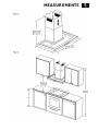
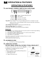
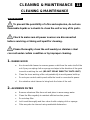
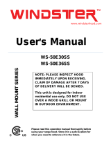
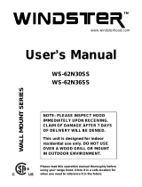
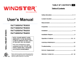
Windster WS96TB30SS is a wall-mount range hood designed for indoor residential use. It features a powerful motor that can effectively remove smoke, grease, and odors from your kitchen. The hood also comes with aluminum filters that are easy to clean and maintain. Additionally, the WS96TB30SS has adjustable height settings, allowing you to customize it to your kitchen's specific needs. With its sleek design and efficient performance, the Windster WS96TB30SS is an excellent choice for any home cook looking to improve their kitchen's air quality.
Windster WS96TB30SS is a wall-mount range hood designed for indoor residential use. It features a powerful motor that can effectively remove smoke, grease, and odors from your kitchen. The hood also comes with aluminum filters that are easy to clean and maintain. Additionally, the WS96TB30SS has adjustable height settings, allowing you to customize it to your kitchen's specific needs. With its sleek design and efficient performance, the Windster WS96TB30SS is an excellent choice for any home cook looking to improve their kitchen's air quality.


-
 1
1
-
 2
2
-
 3
3
-
 4
4
-
 5
5
-
 6
6
-
 7
7
-
 8
8
-
 9
9
-
 10
10
-
 11
11
-
 12
12
-
 13
13
-
 14
14
-
 15
15
-
 16
16


Windster WS96TB30SS User manual
- Category
- Cooker hoods
- Type
- User manual
- This manual is also suitable for
Windster WS96TB30SS is a wall-mount range hood designed for indoor residential use. It features a powerful motor that can effectively remove smoke, grease, and odors from your kitchen. The hood also comes with aluminum filters that are easy to clean and maintain. Additionally, the WS96TB30SS has adjustable height settings, allowing you to customize it to your kitchen's specific needs. With its sleek design and efficient performance, the Windster WS96TB30SS is an excellent choice for any home cook looking to improve their kitchen's air quality.
Ask a question and I''ll find the answer in the document
Finding information in a document is now easier with AI
Related papers
-
Windster WS-62N36SS User manual
-
-
-
-
-
-
-
-
-
Other documents
-
 Windster Hoods WS50E30 User manual
-
 Windster Hoods WS62N30 User manual
-
 Windster Hoods RA7736 User manual
-
Zephyr BMLE30BG Installation guide
-
Zephyr BMIE36CG Installation guide
-
-
-
-
-
Essentials ZNA-M90BS Installation guide


