
DSP-3
Digital Signal Processor
Amplifier Accessory Hardware Manual
*TD-000087-00*
TD-000087-00 Rev.E

This page intentionally left blank.

3
TABLE OF CONTENTS
Warnings, Explanation of Graphical Symbols, and FCC Statement..............................................................4
Section 1: INTRODUCTION Overview......................................................................................................5
General Use Guidelines..................................................................6
QuickStart Guide............................................................................7
Connector & Indicator Descriptions, Illustrations.................12
Hardware Features and Functions...........................................14
Block Diagram..........................................................................................16
Technical Overview..................................................................................17
Section 2: INSTALLATION Unpacking..................................................................................................18
What is Included...................................................................................18
Mounting to QSC DataPort Equipped Amplifiers..................................18
Mounting to the Accessory Remote Mounting Bracket......................19
Connecting Audio Inputs and Outputs...................................................20
Connecting to the DataPort of the DSP-3.................................................21
Connecting to RS-232 Port........................................................................21
Daisy-chaining the DSP-3 Outputs.........................................................22
Connection to Accessory External DC Power Supply.................22
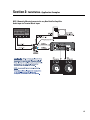
Applications Examples....................................................................23
Section 3: SIGNAL MANAGER SOFTWARE
System Requirements...........................................................................26
Software Installation...........................................................................26
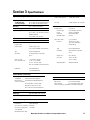
Section 4: SPECIFICATIONS.........................................................................................................................................27
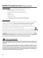
Section 5: ARCHITECT’S & ENGINEER’S SPECIFICATION.....................................................................................29
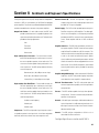
Section 6: APPENDIX
DataPort Pinout.........................................................................................30
RS-232 Pinout ............................................................................................31
Terminal Block Connector Part Number Reference.............................31
Application Information...............................................................32
Preset Operation Notes.................................................................................33
Section 7: QSC INFORMATION Maintenance, Warranty & QSC Contact Information................................34
© Copyright 2001, 2002, QSC Audio Products, Inc.
QSC® is a registered trademark of QSC Audio Products, Inc., Costa Mesa, CA
“QSC” and the QSC logo are registered with the U.S. Patent and Trademark Office

EXPLANATION OF GRAPHICAL
SYMBOLS
The lightning flash with arrowhead symbol, within an
equilateral triangle, is intended to alert the user to the
presence of uninsulated “dangerous voltage” within
the product’s enclosure that may be of sufficient
magnitude to constitute a risk of electric shock to
humans.
The exclamation point within an equilateral tri-
angle is intended to alert the users to the pres-
ence of important operating and maintenance
(servicing) instructions in the literature accom-
panying the product.
CAUTION: To reduce the risk of electric
shock, do not remove the cover. No user-
serviceable parts inside. Refer servicing to
qualified service personnel.
WARNING: To prevent fire or electric shock,
do not expose this equipment to rain or
moisture.
CAUTION
RISK OF ELECTRIC SHOCK
DO NOT OPEN
Federal Communications
Commission (FCC)
Information
NOTE: This equipment has been tested and found to
comply with the limits for a Class B digital device,
pursuant to Part 15 of the FCC Rules. These limits are
designed to provide reasonable protection against
harmful interference in a residential installation. This
equipment generates, uses, and can radiate radio
frequency energy and, if not installed and used in
accordance with the instructions, may cause harmful
interference to radio communications. However, there
is no guarantee that interference will not occur in a
particular installation. If this equipment does cause
harmful interference to radio or television reception,
which can be determined by turning the equipment off
and on, the user is encouraged to try to correct the
interference by one or more of the following mea-
sures:
-Reorient or relocate the receiving antenna.
-Increase the separation between the equipment and
the receiver.
-Connect the equipment into an outlet on a circuit
different from that to which the receiver is conneted.
-Consult the dealeror an experiencedradio/TV tech-
nician for help.
4
SAFEGUARDS
Electrical energy can perform many useful functions. This unit
has been engineered and manufactured to assure your personal
safety. Improper use can result in potential electrical shock or fire
hazards. In order not to defeat the safeguards, observe the
following instructions for its installation, use and servicing.
IMPORTANT SAFETY INFORMATION: PLEASE REVIEW!
WARNING!
WHILE QSC HAS ENDEAVORED TO DEVELOP AND PRODUCE THE MOST DEPENDABLE AND ROBUST DIGITAL SIGNAL PROCESSOR (DSP)
AUDIO PRODUCT FOR YOUR USE, DUE TO THE UNLIMITED AND POTENTIALLY DESTRUCTIVE (TO THE SOUND SYSTEM) CONFIGURATIONS
THAT MAY BE APPLIED TO THE DSP BY THE USER, QSC CANNOT BE HELD RESPONSIBLE FOR DAMAGES RESULTING FROM ANY DEVIATION
OR FAILURE BY THE USER TO STRICTLY FOLLOW THE RECOMMENDATIONS SET FORTH IN THE OWNER’S MANUAL FOR THE INTEGRATION
OF THE DSP-3 AND SIGNAL MANAGER SOFTWARE WITH YOUR SOUND SYSTEM.
ALL RISKS ATTENDANT TO INTEGRATION OF USER-CONFIGURABLE DSP PRODUCTS WITH YOUR SOUND SYSTEM ARE ASSUMED BY YOU.
WHILE QSC STRIVES TO SUPPLY THE HIGHEST QUALITY TECHNICAL SOLUTIONS FOR DIGITAL SIGNAL PROCESSING, IN NO EVENT WILL
QSC OR ITS SUPPLIERS BE HELD LIABLE FOR ANY DAMAGES, CONSEQUENTIAL, INCIDENTAL, OR OTHERWISE, INCLUDING ANY CLAIMS
FOR LOST PROFITS AND/OR SAVINGS RESULTING FROM ANY ATTEMPTED INTEGRATION OF THE DSP-3 AND SIGNAL MANAGER
SOFTWARE WHICH DOES NOT STRICTLY ADHERE TO THE MANUAL’S RECOMMENDATIONS.

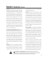
Section 1: Introduction- Overview
5
The DSP-3 is a digital signal processor (
or DSP
) accessory for
audio power amplifiers designed to reduce the need for exter-
nal signal processing while increasing overall system reliability
through distributed intelligence. It is intended primarily for
QSC’s CX, DCA, and Powerlight2 series amplifiers and mounts
directly to the rear panel of the 2-RU, 2-channel models of these
amplifiers. Pre-August, 1999 date-code of the CX, DCA and
Powerlight2, and all ISA models will require use of an external
power supply. Use of the DSP-3 with Powerlight models
requires remote mounting, external power supply and use of a
special interconnect cable (PL6.0/9.0 only). Refer to the
Appen-
dix
for application information. The DSP-3 can also be used
with amplifiers that do not have a QSC DataPort (older QSC
models, non-QSC models) with a reduced feature set and
“remote” mounting/external power.
The signal processing capabilities include an Input Com-
pressor-limiter, multiple Parametric Filters, High- and Low-Pass
Filters, a Shelf Filter, Muting, Attenuation, Multiple Delays,
Polarity Reversal, Audio Routing and Post Crossover Audio
Mixing. Analog-to-digital and digital-to-analog converters are
24 bit resolution, 48 kHz. sampling rate. Additionally, the post-
DSP output signals are daisy-chainable for connection to a
second amplifier. Input sensitivity is selectable and dynamic
range is greater than 93 dB. Inputs and the post-DSP outputs are
electronically balanced. See
Hardware Features
for complete
listing.
Physically, the DSP-3 is a small module that “piggybacks”
onto the back panel of the specified QSC amplifiers. It connects
directly to the DataPort on the back panel and is secured with
supplied hardware. When used with other amplifiers, the DSP-
3 is mounted remotely on a rack-mount accessory that provides
a solid physical mounting platform.
Connections include three D-sub type connections; a DB-9
connector acts as the RS-232 interface and an HD-15 through-
connector provides the DataPort interface to the amplifier and
other QSC DataPort products (if used). The “exposed” side has
four terminal block connectors; 2 audio inputs and 2 post DSP
outputs. There is also a power receptacle for using the DSP-3
with amplifiers that do not provide the required power through
their DataPort, such as the ISA-series, older QSC amplifiers and
non-QSC amplifiers. There are two LED’s; a blue one to indicate
power status and a green one to indicate the presence of an
input signal to the DSP-3.
Control of the DSP-3 is accomplished with the supplied QSC
Signal Manager software. Networked control using the
QSControl platform is also possible (refer to QSControl docu-
mentation for details). Please refer to the software documenta-
tion (software Help file and Readme.txt file) for feature-set and
operation information. This software provides an easy-to-use
graphical user interface where DSP “objects” are placed onto
a palette and interconnects are drawn. This interface allows for
almost infinite configuration possibilities.
Connection of the DSP-3 to the host computer is made by
connecting a serial cable between the DSP-3’s RS-232 port and
the host PC’s available COM port. Once the DSP-3 has been
setup as desired and the configuration saved to the DSP-3,
connection to the PC is no longer required. This feature allows
essentially tamper-proof amplifier DSP setup. Further changes
can be implemented in the field by simply connecting a PC (i.e.
laptop computer) and loading the new setup into the DSP-3.
Note: Powerlight 6.0 and Powerlight 9.0 amplifiers require that pin #9 be removed from the remote
mounting interconnect cable. Amplifier damage may result from use of cable that has pin #9 connections present.
Normal VGA computer monitor cables have pin #9 removed and are usable. Check before use!

IMPORTANT! Pleas read before operating the DSP-3
with your audio system.
The DSP-3 is a professional level DSP product that allows the
user to produce virtually unlimited signal processor varia-
tions and configurations. Because of the infinite configura-
tion possibilities of digital signal processing and the DSP-3,
it is possible to create configurations that may result in
unwanted signals or uncontrollable output
Signal Manager has no way of knowing if the DSP configu-
ration you have designed will produce the results you intend
to produce. You can create signal loops in your configuration
that may oscillate and you may damage your sound system
if you apply such configurations to the DSP-3. When applying
an untested configuration or when designing or experiment-
ing with the DSP-3, it is a very good idea to turn down the
amplifier’s physical gain controls. That way, you won’t
damage your speakers or create very loud sounds if you apply
a configuration that doesn’t do what you thought it would.
As a general rule, DO NOT CREATE SIGNAL LOOPS! Do not
mix the output of a DSP object back into its own input! There
is nothing useful to achieve by doing that, you will only create
an oscillator that could damage you speakers. Also, USE THE
SINE AND NOISE GENERATOR OBJECTS WITH GREAT CAU-
TION! These objects produce signals that can harm your
speakers. Turn down the gain. If you don’t hear a signal when
you think you should, DO NOT INCREASE THE GAIN!!! If the
signal isn’t audible at lower levels, there is something else
wrong. Turning up the gain to full exposes you and your
system to the possibility that some loose connection some-
where will suddenly send a full-amplitude signal through
your sound system.
Like all freely configurable signal processing tools, the DSP-
3 will do what the configuration you design tells it to do,
which may not be what you expect it to do, so use caution.
Section 1: Introduction- DSP-3 General Use Guidelines
6

This quick start section is for those users who want to get up and running with the DSP-3 and Signal Manager
software as quickly as possible. It is in no way a substitute for reviewing the contents of the entire hardware
manual. It is intended for people familiar with the equipment discussed and should be followed up with a review
of the manual and the software help file.
This is the same material covered in the Signal Manager software help file, only presented on paper so that you
may “get right to it”.
1 TURN THE EQUIPMENT OFF & INSTALL THE HARDWARE
If you are using the DSP-3 with.......
QSC Powerlight2, CX, DCA 2-channel, 2-RU am-
plifiers (or later direct-mount applications)
QSC 4-channel CX & DCA amplifiers (or later
models with full-featured DataPort that do not
support direct mounting of the DSP-3)
QSC Powerlight 6.0 or Powerlight 9.0
QSC Powerlight, all except 6.0 & 9.0
a non-DataPort amplifier (QSC USA, PLX or non-
QSC models
Then you need to.....
Mount the DSP-3 to the amplifier by plugging it into the amp’s DataPort and
securing it with the supplied hardware. External power may be required for
older models (see Appendix).
Mount the DSP-3 remotely and connect a QSC DataPort cable between the
amplifier’s DataPort and the DSP-3’s “backside” DataPort. External power
may be required for older models (see top of page 2).
Mount the DSP-3 remotely and connect a MODIFIED QSC DataPort cable
(male-to-female cable with pin #9 removed) between the amplifier’s DataPort
and the DSP-3’s “backside” DataPort. Connect the external power supply to
the DSP-3’s EXTERNAL POWER jack.
Mount the DSP-3 remotely and connect a QSC DataPort cable (male-to-
female) between the amplifier’s DataPort and the DSP-3’s “backside” DataPort.
Connect the external power supply to the DSP-3’s EXTERNAL POWER jack.
Mount the DSP-3 remotely. Connect the DSP-3’s CHANNEL 1 OUTPUT and
CHANNEL 2 OUTPUT to the appropriate amplifier inputs (see p.18 for
pinouts). Connect the external power supply to the DSP-3’s EXTERNAL
POWER jack.
2 CONNECT THE COMPUTER TO THE DSP-3
Use a 9-pin serial data cable to connect the DSP-3’s RS-232 connector to the computer’s available COM port (the 9-pin serial port
connector on the back of the PC). COM1 through COM16 are usable with the Signal Manager software. COM1 is the default port
in Signal Manager; use COM1 for your connection if it is available. If not, you will need to select the appropriate COM port in the
Signal Manager program
after
you install it in step 5.
Section 1: Introduction- Quick Start
7

Section 1: Introduction- Quick Start
3 CONNECT THE AUDIO INPUTS
If your using.......
the CHANNEL 1 INPUT & CHANNEL 2 INPUT connectors
the DataPort input (QSC CM16a or related products)
Then you need to......
connect your input signal source to terminal block connectors
(refer to page 18) and plug the connectors into the CHAN-
NEL 1 INPUT and CHANNEL 2 INPUT receptacles.
connect the DataPort output from the CM16a (or other
related DataPort product) to the DataPort input of the DSP-
3. Use a QSC DataPort cable (male-to-male) for this connec-
tion. Refer to page 19.
4 TURN THE AMP GAIN DOWN, POWER UP THE AMPLIFIER & THE DSP-3
If the DSP-3 requires power from the accessory external power supply, apply
power to the DSP-3 FIRST, then turn on the amplifier. The power supply must be
plugged into an operational AC power receptacle. Then plug the “barrel” connector
(coaxial power plug) fully into the EXTERNAL POWER receptacle on the DSP-3. When
power is properly applied to the DSP-3, the blue POWER LED will be illuminated. Use
a plastic wire-tie (tie-wrap) to secure the accessory power supply’s cord to the DSP-3’s
chassis; there is a metal tab on the chassis for this purpose.
If the DSP-3 is powered by the amplifier’s DataPort, the amplifier must be
connected to an operational AC power receptacle. Then turn the amplifier “on” using
its power switch. The blue POWER LED on the DSP-3 will illuminate a few seconds
after the amplifier’s power switch is activated. If the DSP-3’s blue POWER LED does
not illuminate, you may have an older QSC DataPort equipped amplifier that requires
use of the accessory external power supply (refer to the Appendix for complete
application information).
8

9
Section 1: Introduction- Quick Start
5 INSTALL THE SOFTWARE
1. Place the QSC Signal Manager CD in your computer’s CD drive (typically the D:\ drive). The installation program should run
automatically after several seconds; if it does not,
then
proceed with step 2:
2. Run D:\Setup.exe (replace D: with the drive letter designator appropriate for your system) and follow the instructions displayed.
3. When the installation is complete, you will be presented with a screen that prompts you to view the “Readme” file. Please take
time to read this- it contains important up-to-date information on the software.
4. After installation, you will have an icon on your computer’s “desk top” labeled
Signal Manager
. Use this icon to start the
application (double-click on the
Signal Manager
icon, this will start the program).
5. Using the Menu Bar (see below) at the top of the window, choose the “
Help
” item and read the software help section. The help
system includes the contents of this hardware manual for “paperless” reference.
6. IMPORTANT! The DSP-3 is shipped with all of its presets configured to pass full-range audio signals through both channels.
THIS MAY NOT BE APPROPRIATE FOR YOUR SETUP! Be sure to configure any necessary crossovers , filters, etc. prior
to applying audio signals to the inputs. Damage to equipment may result if these recommendations are not followed.
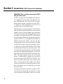
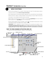
SPLITTER BAR
RESOURCE METER
PANES
COMMUNICATION STATUS PANE
CURSOR POSITION PANE
CAPS LOCK INDICTAOR
NUM LOCK INDICATOR
DSP TOOLS PALETTE
DRAWING TOOLS PALETTE
INPUTS AND OUTPUTS PALETTE
MISC PROCESSORS PALETTEFILTERS PALETTE
MENU BAR
WORKSPACE
PANE
FILE VIEW PANE
STATUS BAR
TITLE
BAR
MAIN PALETTE
CONFIGURATION STATUS
PANE
WHAT THE SIGNAL MANAGER APPLICATION LOOKS LIKE
This screen-shot is what a typical Signal Manager “configuration” looks like (example only):

6 ESTABLISH COMMUNICATION BETWEEN THE DSP-3 & THE COMPUTER
Section 1: Introduction- Quick Start
At this point, you should have everything “up and running”. In the Signal Manager application, check the
COMMUNICATION STATUS PANE
(lower right corner of the Signal Manager window, see above).
If the
COMMUNICATION STATUS PANE
indicates.....
ONLINE
OFFLINE
Then you need to......
Do nothing! Your communication settings match the COM port
you connected the DSP-3 to.
Select
Tools
from the Menu Bar, select
Options
; the
Options
dialog box will open. Click on the
DSP
tab. In the
Serial Port
Selection
field, click on the “down arrow” next to the port
selection data window. A drop down list of COM1 through
COM16 will appear. Select the COM port number that corre-
sponds to the COM port of your computer that the DSP-3 is
connected to. Click
OK
(at the bottom of the dialog box); the
dialog will close. Exit Signal Manager and restart it so that
the newly selected COM port will become active. The
Communication Status pane should now indicate ONLINE if
everything was connected and set up properly.
7 ENSURE THE AMPLIFIER IS TURNED DOWN AND THAT YOU HAVE SUITABLE
SPEAKERS CONNECTED FOR YOUR INTENDED CONFIGURATION
For familiarization with the DSP-3 and the Signal Manager software, we recommend that you use a pair of full range
speakers connected to your amplifier and that the amplifier gain be reduced to the minimum useful setting. This will
allow you to configure the DSP-3 almost anyway you desire while providing audio output to verify that the DSP-3 is
doing as you intend. Small, high-power rated monitor speakers are perfect for the task.
Better safe than sorry! Don’t turn you amp all the way up; if communica-
tions between the computer and DSP-3 fail for any reason, unexpected
output transients could damage your speakers
8 CREATE A SIMPLE DSP CONFIGURATION
10
From the Menu Bar, select
Configuration
,
New
. If there was a default configuration on the Workspace, you will be prompted to close
the “current” configuration first.
Locate the Inputs and Outputs palette; left-click on the icon labeled IN1. Move your pointer into the upper left area of the Workspace
and left-click the mouse again. The IN1 object should now be on your workspace.

Section 1: Introduction- Quick Start
The last applied configuration that is “running” in the DSP-3 when it is turned off becomes the active configuration again once
the power is turned back on to the DSP-3. This ensures that the system “comes up” just as it was left last time it was powered
down.
If you decide to edit an existing configuration, you will need to “unlock” the configuration after opening it. Just select
Configuration
from the Menu Bar, then select
Edit
. The palettes that were “grayed out” will now appear in their normal,
colored state and you will be able to edit the configuration. After your editing is complete, select
Configuration
from the Menu
Bar and then
Apply to DSP.
That’s it for the “Quick Start”. For more information, review this manual and the software’s help file.
11
Now select the OUT1 icon from the same palette (left click on the OUT1 icon). Move your pointer into the upper right area of the
workspace, in line with the IN1 object you just placed, and left click again. The OUT1 object should appear.
Select the GAIN icon in the MISC PROCESSORS palette (it looks like a little wedge and is the left-most icon in this palette). Move your
pointer to the workspace in between (and in line with) the IN1 and OUT1 objects; click the mouse button again. The GAIN object should
appear.
Go to the DRAWING TOOLS palette and select the DRAW (pencil) icon. Notice that the IN1 object has a small yellow-colored “node”
on its right side. This is its connection node or the point that “wires” are drawn from. Similarly, note the same yellow-colored nodes on the
GAIN and OUT1 objects. Draw a “wire” from the IN1 object to the left side of the GAIN object. Draw another “wire” from the GAIN object
(right side) to the OUT1 object.
The DRAW tool works by clicking on one of the nodes that you want to draw a wire between, then, while holding down the
mouse button, dragging the wire to the other node. You can change the drawing mode from click-drag-release wiring to
click-click wiring in the
Tools
,
Options
dialog box; select the
Drawing
tab and make any desired drawing “behavior” changes.
When everything is placed on the workspace and connected with “wires”, go to the Menu Bar and select Configuration, then Apply
to DSP (or just click on the “Apply to DSP” icon in the DSP Tools palette). This will send your configuration (and any object parameter settings)
from the computer to the DSP-3. The DSP-3’s outputs will be muted while the configuration is loaded. For complex configurations, this could
take several seconds.
If you have active audio inputs connected to the DSP-3 and the amplifier’s gain is sufficient, you will probably hear your audio material
at this point. If not, double-click on each of the GAIN objects and increase the gain setting as required.
Also in the
Tools
,
Options
dialog,
the
DSP
tab has settings for input and output sensitivity for the DSP-3; these may require adjustment dependant on your particular set up.
The
Communication Status
pane should indicate “ONLINE” and the
Configuration Status
pane should indicate “ACTIVE”. If you get
an error message when applying the configuration to the DSP-3 (i.e. “Failed to connect to DSP-3”) check the cable connection between the
DSP-3 and the computer’s COM port. Ensure that the correct COM port is selected in Signal Manager’s
Tools
,
Options
,
DSP
settings dialog
box.
Repeat the above procedure, this time using IN2, OUT2 and a GAIN object. This will give you a signal path with gain adjustment for
channel 2. Be sure to “Apply to DSP”. This sends your updated configuration from your computer to the DSP-3.

Section 1: Introduction- Basic Connector & Indicator Descriptions
12
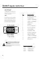
RS-232- This DB-9 fe-
male jack is where the
serial cable between the
DSP-3 and the computer
is plugged in.
FRONT PANEL
CH 1 INPUT, CH 2 INPUT- These terminal-block
jacks (receptacles) are where you connect the
line-level audio inputs to the DSP-3.
They are electronically balanced with an input
impedance of 8.3k Ohm. If used in an unbalanced
configuration, the input impedance is 3.7k Ohms.
EXTERNAL POWER-
2.5mm barrel connector-
Center (+), Outer(-), 15
VDC, 300mA. Use only if
your amplifier does not
supply the required op-
erating voltage from its
DataPort (or non-
DataPort amps).
CH 1 OUTPUT, CH2 OUTPUT-- These terminal-
block jacks provides post-DSP (processed) signal
from the DSP-3 for downstream devices (ampli-
fiers, monitoring busses, daisy-chaining the pro-
cessed signal to a second amplifier). In the case
of non-DataPort amplifiers, these are the DSP-3
output that gets connected to your amplifier’s
input connector.
DATAPORT- This is the “in-
put” DataPort. If the DSP-3 is
used with QSC DataPort prod-
ucts that can supply the audio
inputs or provide amplifier con-
trol & monitoring, this is where
they are connected to the DSP-
3.
SIGNAL indicator- This green
LED illuminates when the
DSP-3 detects an input signal
on either channel. Dual bright-
ness levels indicate signal
level. At -40dB, it will light
dimly; at -20dB it will light
brightly.
POWER indicator- This blue
LED illuminates when the DSP-
3 has power properly applied.

Section 1: Introduction- Basic Connector & Indicator Descriptions
13
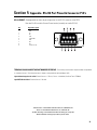
REAR PANEL
OVERALL
DATAPORT (unlabeled)- This is the “output”
DataPort.
If the DSP-3 is directly mounted on a 2-RU QSC
DataPort equipped amplifier, this connector plugs
into the amplifier’s DataPort connector.
If used with 3-RU QSC DataPort equipped amplifi-
ers, the DSP-3 will need to be remotely mounted
and a male-female DataPort cable used to inter-
connect the amp & DSP-3.
If used with a non-DataPort amp (QSC or other),
this connector will not be used.

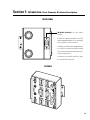
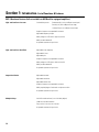
Section 1: Introduction- List of Functions & Features
14
DSP-3 Hardware Features (full set available to QSC DataPort equipped amplifiers):
High- and Low-Pass Crossover Selectable
responses: Butterworth (6,12,18 or 24 dB per octave slope)
Bessel (6,12,18 or 24 dB per octave slope)
Linkwitz-Riley (12 or 24 dB per octave slope)
Graphical response curve provided in software
Adjustable frequency & slope
Ability to bypass all EQ with a single mouse click
Ability to add or delete EQ
Assignable anywhere in signal chain
High- and Low-Pass Shelf Filter
Adjustable corner frequency
Adjustable Q factor
Adjustable gain
Graphical response curve provided in software
Ability to bypass all EQ with a single mouse click
Ability to add or delete EQ
Assignable anywhere in signal chain
Output Peak Limiter
Adjustable threshold
Adjustable attack time
Adjustable release time
Graphical response curve provided in software
Ability to quickly bypass limiter with a single mouse click
Assignable anywhere in signal chain
Multiple Delays
910 millisecond maximum ( sum of all delay objects)
20.83 microsecond increments
Entry can be in seconds, feet or meters
Assignable anywhere in signal chain.

Section 1: Introduction- List of Functions & Features
15
Parametric EQ
Adjustable frequency
Adjustable gain
Adjustable Q factor
Ability to bypass all EQ with a single mouse click
Ability to add or delete EQ
Graphical response curve provided in software
Assignable anywhere in the signal chain
Signal Compressor
Adjustable attack and release times
Adjustable Gain
Adjustable threshold
Adjustable compression ratio
Graphical response curve provided in software
Assignable anywhere in the signal chain
Signal Level Meter
Peak or rms response
Signal Attenuation
(mute or bypass)
Mix Post Crossover Audio
(2 to 1 mixer with
mute
and
lock all channels
featured)
Signal Splitter
External Contact Closure Sensing (pin #9 of RS-232, operates with ”Switched Gain” objects in Signal Manager software)
Pink & White Noise Generator
Variable Frequency Tone Generator
Clip & Protect Indication
Signal Polarity Reversal

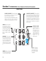
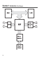
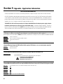
Section 1: Introduction- Block Diagram
16

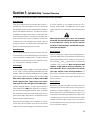
Section 1: Introduction- Technical Overview
17
Audio Input Path
There are two audio channels each with two input connectors, a
balanced 3-pin ‘euro’ terminal block jack and an electronically
balanced DataPort input. The inputs are protected with a filter that
prevents radio frequency interference. The inputs have software-
selectable full scale input level sensitivity; this is the level at which
the analog to digital converters reach their full scale digital value.
Refer to the
Specifications
section for full details. The DataPort is
scaled to clip with a full scale digital input if the DSP-3 does not
change gain structure. Each CODEC input is diode protected to
prevent any large signal from destroying its inputs.
Audio Output Path
The first stage the audio passes through is an inverting gain stage.
The second stage is a second order Butterworth low pass filter that
removes high frequency sampling artifacts. The signal is then sent
out of the DSP-3 through the DataPort or the output ‘Euro’ connec-
tors. The output level is selectable in software.
Power Supply
No external power supply is needed for use with the CX, DCA and
PL2 two-channel, 2 RU series amplifiers produced with date-codes
of August, 1999 or later. With these models, the DSP-3 is supplied
power from the amplifier via the DataPort (HD-15) connection. CX,
DCA, and PL2 amps made prior to August 1999 DO NOT
provide adequate power supply voltage to the module,
requiring the use of the same type of external DC supply as
used with Powerlight amplifiers. The amps in question will have a
serial number PRIOR to 0899XXXXX, where the first four digits of
the serial number are the MMYY datecode. Again, the modules
WILL work with these amps just fine, but will require the use of our
external power supply. External power is not required for all other
directly-mounted-to-amplifier situations.
When used with the Powerlight series of amplifiers (or 3 RU & 4-
channel amps), the DSP-3 requires use of the accessory external
supply. The accessory external supply is also used when connecting
to non-QSC amplifiers (or any amplifier that does not have a
DataPort). External power is provided by the accessory power
supply (“wall wart”) via a coaxial power cord jack on the back of the
DSP-3.
When using the external power source, we recommend
that the DSP-3 be powered-up before the amplifier in order
to insure trouble-free start-up. This will also avoid the
possibility of “thumps & bumps” should the DSP-3 be pow-
ered up after the amplifier.
Data Acquisition
The DSP-3 samples the I
MON
and V
MON
(current and voltage monitor-
ing from the amplifier) lines of QSC amplifiers (via the DataPort) in
order to perform dynamics (limiter, compressor, etc.) processing.
The four inputs (I
MON
and V
MON
for both channels) are continuously
sampled by a four channel ADC. When used with non-QSC
amplifiers or QSC amplifiers that have no DataPort, the
power limiter DSP “object” is not available as this function
relies upon amplifier current and voltage feedback. The
DSP-3 will also not be able to monitor the protect or power status
of the amplifier as these features require amplifier data via a
DataPort connection.
Contact Closure
One contact closure input is provided. It uses pin 9 of the RS-232
DB-9 connector (not normally used for RS-232). Shorting this pin to
ground with a maximum impedance of 1.3 kOhms will cause a
general purpose I/O pin of the DSP to be pulled to a logic low. The
current release of Signal Manager software uses this input to allow
switched gain functions. Each of the Switched Gain blocks will be
switched simultaneously by the single contact closure (switch).
Each Switched Gain block has a two gain settings; one for open and
one for closed switch conditions.
This portion of the introduction provides some of the technical details of the DSP-3.

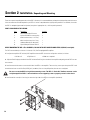
Section 2: Installation- Unpacking and Mounting
18
UNPACKING
There are no special unpacking precautions for the DSP-3. However, it is recommended that you keep the original packing material for reuse
in the rare event that service be required for your DSP-3. If service is required and the original packing material is not available, insure that
the DSP-3 is adequately protected for shipment (strong box of appropriate size , sufficient packing material).
WHAT IS INCLUDED IN THE CARTON:
Item Description Quantity
1- DSP-3 Digital Signal Processor 1
2- 3-pin terminal block connector plug 4
3- #4-40 machine screw, 1.125” long 2
4- #8-32 machine screw, 0.312” long 1
5- Hardware Manual (this document) 1
6- Signal Manager Software CD disk 1
DIRECT MOUNTING THE DSP-3 TO 2-CHANNEL, 2 RU QSC DATAPORT EQUIPPED AMPLIFIERS (CX, DCA, Powerlight2)
The DSP-3 mounts directly to the rear of 2-channel, 2-RU, DataPort equipped QSC amplifiers.
1- Configure the amplifiers DIP switches (QSC amplifiers where the DSP-3 covers the configuration switches) as follows:
•All filters off •Clip limiter off •Mode set as required
2- Align the DataPort plug on the back of the DSP-3 with the DataPort jack on the back of the amplifier and gently push the DSP-3 to seat
the connector.
3- Install the two #4-40 screws to secure the left side of the DSP-3 to the amplifier. These two long screws pass through the DSP-3 and
thread into the inserts on the DataPort (HD15) jack. (see below). Use a #1-size phillips driver; be sure not to overtighten.
Be sure to secure the DSP-3 using all three mounting screws. The DSP-3’s “backside” DataPort connector can be
easily damaged if the DSP-3 is twisted and there are no supporting screws to properly secure it to the chassis.
4- Install the #8-32 screw (0.312 inch long) to secure the right side of the DSP-3 to the amplifier (see below).

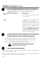
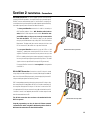
Section 2: Installation- Remote mounting (4-ch., Powerlight & non QSC amp’s)
19
REMOTE MOUNTING THE DSP-3 : 4-Channel CX and DCA , Powerlight series, and all non-QSC amplifiers
Use of the DSP-3 with the 4-channel CX and DCA and all Powerlight amplifiers requires the remote mounting of the DSP-3. Use with non-
QSC amplifiers also requires remote mounting. Keep in mind that all applications that use amplifiers that do not have a DataPort ( i.e. non-
QSC amplifiers) some of the dynamic processing capabilities of the DSP-3 will not be available.
Accessory Remote Mounting Bracket- This accessory is a 19”, 2-RU panel with mounting facilities for up to four DSP-3 modules. It is
intended to be mounted to the rear-support rails of an equipment rack. The bracket kit comes with one large bracket ( the 19”, 2-RU size)
and four smaller right-angle brackets that are used for securely mounting up to four DSP-3’s in a 2-RU space. Adjustable rack ears are
included for maximum mounting flexibility.
3- Mount the main bracket assembly in your equipment rack
between the rear support rails.
2- Attach the DSP-3 & right-angle bracket to the main 19” bracket as shown, below.
1- Attach the right-angle bracket to the DSP-3 module. The right-angle bracket is attached as shown, below.
4- Attach the inputs, outputs, DataPorts,
RS-232 and external power as required.

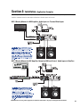
20
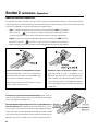
Section 2: Installation- Connections
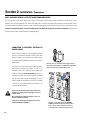
CONNECTING AUDIO INPUTS AND OUTPUTS:
The audio inputs and outputs of the DSP-3 use 3-pin “Phoenix”-type (Euro-style) terminal block connectors. These connectors allow pre-
wiring of inputs without any soldering and allow for rerouting of audio inputs by simply interchanging connector locations without the need
for any tools. See Appendix for connector manufacturer’s part number reference.
To connect your signal wire to the terminal-block plug- back the screws out
a few turns to open the wire-clamp, carefully insert the conductors into the proper
location, and retighten the clamping screw.
The recommended stripping length for the wires is approximately 6 to 8
mm ( 1/4 to 5/16 inch). When stripping the audio cable, be careful not to nick or
cut the conductor strands. After each conductor has been stripped and dressed,
insert it fully into the connector and tighten the retaining screw. When stranded
wire is used, carefully twist the conductor strands together so that when they are
inserted into the connector assembly, no loose strands short adjacent terminals.
Unbalanced inputs can be used if required. If unbal-
anced audio sources are used, it is preferable to use an
appropriate audio transformer (or other unbalanced-to-bal-
anced “converter”) to provide a balanced input to the DSP-3.
If this is not possible, then it is recommended that the negative
terminal and shield terminal be connected to one another with
a jumper wire.
Balanced connection is recommended for all inputs.
The terminal block inputs on the DSP-3 are electronically
balanced. Balanced input cables are recommended to mini-
mize noise pick up and prevent ground loops.
With the connector oriented as shown at the right, connect the
positive (+) signal wire to the left-most
Inputs- The audio input can be from one of two sources; the front-panel DataPort OR the terminal-block
INPUT connectors. Do not use both sets of inputs at the same time! Use balanced connections
for the lowest possible noise levels and for minimizing the possibility of hum inducing ground loops.
Outputs- The DSP-3’s post-DSP (processed) audio is output to the rear-panel DataPort AND the terminal-
block OUTPUT connectors. The OUTPUT’s can be used for daisy-chaining the processed audio to
additional amplifiers, even when connected to a DataPort-equipped amplifier via the rear-panel DataPort.
Page is loading ...
Page is loading ...
Page is loading ...
Page is loading ...
Page is loading ...
Page is loading ...
Page is loading ...
Page is loading ...
Page is loading ...
Page is loading ...
Page is loading ...
Page is loading ...
Page is loading ...
Page is loading ...
Page is loading ...
-
 1
1
-
 2
2
-
 3
3
-
 4
4
-
 5
5
-
 6
6
-
 7
7
-
 8
8
-
 9
9
-
 10
10
-
 11
11
-
 12
12
-
 13
13
-
 14
14
-
 15
15
-
 16
16
-
 17
17
-
 18
18
-
 19
19
-
 20
20
-
 21
21
-
 22
22
-
 23
23
-
 24
24
-
 25
25
-
 26
26
-
 27
27
-
 28
28
-
 29
29
-
 30
30
-
 31
31
-
 32
32
-
 33
33
-
 34
34
-
 35
35


Ask a question and I''ll find the answer in the document
Finding information in a document is now easier with AI
Related papers
Other documents
-
QSC Audio Network Audio Systems User manual
-
-
-
-
-
ARC Audio PRO SERIES DSP SOFTWARE Owner's manual
-
-
Unika DCA-1100 Owner's manual
-
-