Smeg SX91VLSA Datasheet

Category
Cookers
Type
Datasheet

Smeg SX91VLSA is a versatile cooking appliance that combines a gas hob with an electric oven. The gas burners offer precise heat control for various cooking techniques, while the electric oven provides accurate temperature settings for baking and roasting. With its spacious interior and multiple functions, including grill and defrost, this appliance is well-equipped to handle a wide range of culinary tasks, making it a valuable addition to any kitchen.

Smeg SX91VLSA is a versatile cooking appliance that combines a gas hob with an electric oven. The gas burners offer precise heat control for various cooking techniques, while the electric oven provides accurate temperature settings for baking and roasting. With its spacious interior and multiple functions, including grill and defrost, this appliance is well-equipped to handle a wide range of culinary tasks, making it a valuable addition to any kitchen.

Contents
3
THESE INSTRUCTIONS ARE VALID ONLY FOR END USER COUNTRIES WHOSE
IDENTIFICATION SYMBOLS APPEAR ON THE COVER OF THIS MANUAL.
INSTRUCTIONS FOR THE INSTALLER: these are for the qualified technician who must carry out a
suitable check of the gas system, install the appliance, set it functioning and carry out an inspection
test.
INSTRUCTIONS FOR THE USER: these contain user advice, description of the commands and the
correct procedures for cleaning and maintenance of the appliance.
1 INSTRUCTIONS FOR SA
F
E AND PROPER USE
_
______________________________4
2 INSTALLATION OF THE APPLIANCE ________________________________________6
3 ADAPTATION TO DIFFERENT TYPES OF GAS _______________________________10
4 FINAL OPERATIONS ____________________________________________________13
5 DESCRIPTION OF FRONT PANEL CONTROLS _______________________________15
6 USE OF THE COOKING HOB______________________________________________17
7 USE OF THE OVEN _____________________________________________________19
8 CLEANING AND MAINTENANCE ___________________________________________22
9 EXTRAORDINARY MAINTENANCE _________________________________________24
Introduction
4
1 INSTRUCTIONS FOR SAFE AND PROPER USE
THIS MANUAL IS AN INTEGRAL PART OF THE APPLIANCE AND THEREFORE MUST BE KEPT
IN ITS ENTIRETY AND IN AN ACCESSIBLE PLACE FOR THE WHOLE WORKING LIFE OF THE
COOKER. WE ADVISE READING THIS MANUAL AND ALL THE INSTRUCTIONS THEREIN
BEFORE USING THE COOKER. ALSO KEEP THE SERIES OF NOZZLES SUPPLIED.
INSTALLATION MUST BE CARRIED OUT BY QUALIFIED PERSONNEL IN ACCORDANCE WITH
THE REGULATIONS IN FORCE. THIS APPLIANCE IS INTENDED FOR DOMESTIC USES AND
CONFORMS TO CURRENT REGULATIONS IN FORCE. THE APPLIANCE HAS BEEN BUILT TO
CARRY OUT THE FOLLOWING FUNCTIONS: COOKING AND HEATING-UP OF FOOD. ALL
OTHER USES ARE CONSIDERED IMPROPER.
THE MANUFACTURER DECLINES ALL RESPONSIBILITY FOR IMPROPER USE.
DO NOT LEAVE THE PACKING IN THE HOME ENVIRONMENT. SEPARATE THE VARIOUS
WASTE MATERIALS AND TAKE THEM TO THE NEAREST SPECIAL GARBAGE COLLECTION
CENTRE.
IT IS OBLIGATORY FOR THE ELECTRICAL SYSTEM TO BE GROUNDED ACCORDING TO THE
METHODS REQUIRED BY SAFETY RULES.
WHEN LINKING UP TO MAINS BY PLUG AND SOCKET, MAKE SURE THAT BOTH ARE
COMPATIBLE AND CONNECT BY MEANS OF A POWER CABLE COMPLYING WITH
APPLICABLE REGULATIONS.
THE SOCKET MUST BE ACCESSIBLE AFTER THE APPLIANCE HAS BEEN BUILT IN.
NEVER UNPLUG BY PULLING ON THE CABLE.
IMMEDIATELY AFTER INSTALLATION CARRY OUT A BRIEF INSPECTION TEST OF THE
APPLIANCE, FOLLOWING THE INSTRUCTIONS BELOW. SHOULD THE APPLIANCE NOT
FUNCTION, DISCONNECT IT FROM THE SUPPLY AND CALL THE NEAREST TECHNICAL
ASSISTANCE CENTRE.
NEVER ATTEMPT TO REPAIR THE APPLIANCE.
WHEN NOT IN USE, MAKE SURE THAT THE CONTROL KNOBS ARE IN THE CORRECT (OFF)
POSITION
.
NEVER PUT INFLAMMABLE OBJECTS IN THE OVEN: THEY COULD BE ACCIDENTALLY
LIGHTED AND CAUSE FIRES.
THE I.D. PLATE WITH TECHNICAL DATA, REGISTRATION NUMBER AND BRAND NAME IS
POSITIONED VISIBLY IN THE STORAGE COMPARTMENT.
THE PLATE MUST NOT BE REMOVED.
DO NOT PUT PANS WITHOUT PERFECTLY SMOOTH AND FLAT BOTTOMS ON THE COOKING
HOB RACKS.
DO NOT USE CONTAINERS OR BROILERS THAT EXTEND BEYOND THE OUTER PERIMETER
OF THE HOB.
Introduction
5
LOWER THE GLASS COVER SLOWLY AND BY HAND.
WARNING: THE GLASS COVER MAY SHATTER IF IT OVERHEATS. SWITCH OFF ALL RINGS
AND WAIT FOR THEM TO COOL DOWN BEFORE CLOSING THE COVER.
DURING USE THE APPLIANCE BECOMES VERY HOT. TAKE CARE NOT TO TOUCH THE
HEATING ELEMENTS INSIDE THE OVEN.
THE APPLIANCE IS DESIGNED FOR USE BY ADULTS. DO NOT ALLOW CHILDREN TO GO
NEAR OR PLAY WITH IT.
WHEN OPERATING THE GRILL ALL ACCESSIBLE PARTS COULD BECOME VERY HOT: KEEP
OUT OF THE WAY OF CHILDREN.
IF THE APPLIANCE IS TO BE POSITIONED ON A PLATFORM IT MUST BE INSTALLED IN SUCH
A WAY AS TO PREVENT IT FROM SLIPPING OFF THE FORMER.
BEFORE THE APPLIANCE IS PUT INTO OPERATION, ALL THE LABELS AND PROTECTIVE
FILMS APPLIED INSIDE OR OUTSIDE MUST BE REMOVED.
The manufacturer declines all responsibility for damage to persons or things caused by non-
observance of the above prescriptions or by interference with any part of the appliance or by the use
of non-original spares.
Instruction for the installer
6
2 INSTALLATION OF THE APPLIANCE
The appliance must be installed by a qualified technician and according to the regulations in force.
This appliance may be installed next to a wall which is higher than the appliance, with a minimum
distance of 5 cm from the side of the appliance, as shown in drawings A and B showing the correct
installation conditions. Any wall cupboards or shelves must be at a distance of at least 75 cm above
the work surface.
A
B
Built-in appliance Free-standing installation
Instruction for the installer
7
2.1 Electrical connection
Make sure that the power line voltage matches the specifications indicated on the rating plate located
inside the storage compartment.
This rating plate must never be removed.
If the appliance is hooked-up to the supply by means of a fixed connection, install a multipolar cut-out
device on the line, with contact opening distance equal to or greater than 3 mm, located near the
appliance and in an easily reachable position.
Hook-up to the supply may be fixed or with plug and socket. In the latter case the plug and socket
must be suitable for the cable employed and conform with the regulations in force. Regardless of the
type of connection, earthing of the appliance is absolutely obligatory. Before connection make sure
that the supply line is suitably earthed. Avoid the use of reducers, adapters or shunts.
If the power cable is replaced, the wire section on the new cable must
not be less than 1 mm
2
(3 x 1 cable), keeping in mind that the end to be
connected to the hob must have the ground wire (yellow-green) longer
by at least 20 mm. Use only H05V2V2-F cable or similar which has a
maximum temperature of 90°C. This must be done by a specialised
technician, who must connect the cooker to the electricity supply
according to the diagram shown here.
L = brown
N = blue
= yellow-green.
The values indicated above refer to the cross-section of the internal conductor.
2.2 Ventilation requirements
The room containing the appliance should have an air supply in accordance with the standards in
force.
The room where the appliance is installed must have enough air flow as required for the regular
combustion of gas and by the necessary air exchange of the same room. The air vent, protected by
grills, must be suitably dimensioned in compliance with the current regulations and positioned so that
no part of it is obstructed.
2.3
Extraction of the combustion products
The combustion products must be extracted by means of hoods connected to a natural draught
chimney whose efficiency is certain or via forced extraction.
Instruction for the installer
8
2.4 Connection to gas
At the end of the installation, check for any leaks with a soapy solution, never with a naked
flame.
THE TIGHTENING TORQUE BETWEEN CONNECTIONS THAT INCORPORATE A GASKET MUST
NOT EXCEED 10Nm.
2.4.1 Connector installation
Carefully screw the connector B to the gas
outlet A of the appliance, placing the seal C
between them.
The connector must be screwed so that it
remains vertical as shown in the adjacent
figure.
2.4.2 Connection with a rubber hose
Installation of the standards-compliant rubber hose must be carried out so that the hose length is no
greater than 1.5 metres. Make sure that the hose does not come into contact with moving parts and is
not squashed. The inside diameter of the hose must be 8 mm for LIQUID GAS and 13 mm for
NATURAL GAS and CITY GAS.
Verify that all the following conditions are met:
the hose is fixed to the hose connection with safety clamps;
no part of the hose is in contact with the hot walls (max. 50 °C);
the hose is not under traction or tension and has no tight curves or twists;
the hose is not in contact with sharp objects or sharp corners;
if the hose is not perfectly airtight and leaks gas, do not try to repair it: replace it with a new
hose;
verify that the hose is not past its expiry date (serigraphed on the hose itself).
Instruction for the installer
9
CONNECTION USING RUBBER HOSES COMPLYING WITH THE CURRENT REGULATIONS IS
ONLY PERMITTED IF THE HOSE CAN BE INSPECTED ALONG ITS ENTIRE LENGTH.
2.4.3 Connection to liquid gas
Both the pressure regulator and the connection to the cylinder must be standards-compliant.
Make the connection to the gas mains using a rubber hose whose specifications comply with the
current regulations (verify that the reference standard is stamped on the hose).
After having installed the connector as
indicated in “2.4.1 Connector installation”,
fit the small hose connector E to the large
hose connector D.
Place the seal F between the lock just
obtained and the previously installed
connector.
Then, push the rubber hose onto the hose
connector E and secure it with a clamp
that is compliant with the current standard.
2.4.4 Connection to natural gas
After having installed the connector as
indicated in “2.4.1 Connector installation”,
Fit the large hose connector
D by placing
the seal F between the previously installed
connector.
Push the rubber hose D onto the hose
connector A and secure it with the clamp
E that is compliant with the current
standard.
2.4.5 Connection with a flexible steel hose (for all types of gas)
This type of connection can be made on both built-in and free-standing appliances. Only use
standards-compliant steel hoses whose length is not greater than 2 metres.
After having installed the connector as indicated in “2.4.1 Connector installation”, screw the end of the
flexible hose to the threaded ½ external gas connector (ISO 228-1), placing the seal in between.
Instruction for the installer
10
3 ADAPTATION TO DIFFERENT TYPES OF GAS
Before performing any cleaning or maintenance work, disconnect the appliance from the power
supply.
The cooker is set for LPG G30/G31 (3+) at a pressure of 28/37 mbar. In the case of functioning with
other types of gas the burner nozzles must be changed and the minimum flame adjusted on the gas
taps. To change the nozzles, proceed as described below.
3.1 Replacement of nozzles on the hob
This operation requires no primary air regulation.
1. Extract the racks and remove all the caps and flame-spreader crowns;
2. unscrew the burner nozzles with a 7 mm socket wrench;
3. replace the nozzles according to the type of gas to be used and the description in paragraph “3.2 /
3.3 Burner and nozzle characteristics table”.
4. Replace the burners in the correct position.
3.2 Arrangement of burners on cooking hob
BURNERS
1. Auxiliary
2. Semi-rapid
3. Rapid
4. Triple crown
Instruction for the installer
11
3.3 Burner and nozzle characteristics table
Burner
Rated
heating
capacity
(kW)
LPG G30/G31 28/37 mbar
Nozzle
diameter
1/100 mm
By-pass
mm
1/100
Reduced
flowrate
(W)
Flowrate
g/h G30
Flowrate
g/h G31
Auxiliary 1 50 30 350 73 71
Semi-rapid 1.8 65 33 450 131 129
Rapid 3 85 45 800 218 214
Triple crown 3.5 94 63 1500 255 250
Maxi oven 4.2 100
62
1200 306 300
Grand grill 3.7 95 70 1700 269 264
Burner
Rated
heating
capacity
(kW)
NATURAL GAS – G20 20 mbar
Nozzle diameter
1/100 mm
Reduced Flowrate
(W)
Auxiliary 1 72 (X)
400
Semi-rapid 1.8 97 (Z)
500
Rapid 3 115 (Y) 800
Triple crown 3.5 140 (6) 1600
Maxi oven 4.2
150 (H3)
Grand Grill 3.7
140 (H3)
1200
1700
Instruction for the installer
12
3.4 Adjustment of the oven burner
To adjust the oven burners follow the procedure described
below from inside the oven:
Open the oven door;
Remove the oven dish and shelf.
Lift up the oven floor and remove.
3.4.1 Replacement of the oven and grill burner nozzles
Loosen the fixing screws A on the oven burner.
Push the burner B towards the right to get to the
nozzle.
Use a 7 socket wrench to change the nozzle, fitting
the one for the type of gas to be used (see point
“3.2/3.3 Table of burner and nozzle characteristics”).
Instruction for the installer
13
4 FINAL OPERATIONS
After replacing the nozzles, reposition the flame-spreader crowns, the burner caps and the racks.
Following adjustment to a gas other than the preset one, replace the gas adjustment label fixed to the
appliance with the one corresponding to the new gas. This label is in the pack together with the
nozzles.
4.1 Regulation of the hob burner minimum level for natural gas
Light the burner and turn it to the minimum position
. Extract the gas tap
knob and turn the adjustment screw at the side of the tap rod until the
correct minimum flame is achieved.
Replace the knob and check burner flame stability: (rapidly turning the
knob from maximum to minimum position, the flame should not go out).
Repeat the operation on all the gas taps.
For models with valves, keep the knob at minimum level for about 1 minute to keep the flame lit and to
activate the safety device.
4.2 Regulation of the hob burner minimum level for LPG
For regulating the minimum with LPG, the screw at the side of the tap rod must be turned clockwise
all the way.
The bypass diameters for each individual burner are shown in paragraph “3.2 / 3.3 Burner and nozzle
characteristics table”. Once the regulation has been completed, replace the seal on the by-passes
using paint or similar materials.
4.3 Regulation of the oven burner minimum level
The oven thermostat is equipped with a by-pass to regulate the minimum level, which is visible
underneath the thermostat knob.
When the gas type is changed, the by-pass should be regulated as follows:
1. Turn on the oven burner to maximum for 10/15 minutes with the door closed and without the floor.
Turn the knob to the minimum temperature, remove the knob and regulate using a flat
screwdriver.
2. For LPG turn the by-pass screw clockwise as far as it will go. The by-pass diameter is shown in
the paragraph “3.2 / 3.3 Burner and nozzle characteristics table”.
3. For natural gas, regulate the by-pass so that turning the thermostat knob from minimum to
maximum the flame remains stable and constant. Once the regulation has been completed,
replace the seal on the by-pass using paint or similar materials. Close the oven door and make
sure that the burner stays on minimum.
Instruction for the installer
14
4.4 Regulation of the grill burner minimum level
The grill burner tap is equipped with a by-pass to regulate the minimum level, which is visible at the
side of the tap rod.
When the gas type is changed, the by-pass should be regulated as follows:
1. Turn on the grill burner to maximum for 10/15 minutes with the door closed.
Turn the knob to the minimum temperature, remove the knob and regulate using a flat
screwdriver.
2. For LPG turn the by-pass screw clockwise as far as it will go. The by-pass diameter is shown in
the paragraph “3.2 / 3.3 Burner and nozzle characteristics table”.
3. For natural gas, regulate the by-pass so that turning the knob from minimum to maximum the
flame remains stable and constant. Once the regulation has been completed, replace the seal on
the by-pass using paint or similar materials. Close the oven door and make sure that the burner
stays on minimum.
4.5 Positioning and levelling of the appliance
Having carried out the electricity and gas hook-up, level the appliance using the four adjustable legs.
For best cooking the appliance must be perfectly level.
Depending on the model you have purchased, the foot height adjustment range may vary from 70 to
95 mm and from 110 to 160 mm. These heights refer to the distance between the highest point of the
foot (fixed part) and the lowest point (movable part which rests on the floor).
Instruction for the user
15
5 DESCRIPTION OF FRONT PANEL CONTROLS
All the oven controls are grouped together on the front panel. The table below provides a description
of the symbols used.
FRONT LEFT BURNER
OVEN BURNER THERMOSTAT KNOB
BACK LEFT BURNER
GRILL BURNER
CENTRAL BURNER
BURNER IGNITION BUTTON
BACK RIGHT BURNER
OVEN LIGHT SWITCH
FRONT RIGHT BURNER
BURNER IGNITION BUTTON (on some models only)
This button allows to supply the ignition spark needed to light the gas
burners of the appliance.
COOKING HOB CONTROL KNOB
The flame is lit by turning the knob anticlockwise to the minimum
flame setting (
), while simultaneously pressing the burner ignition
button. In the models not equipped with the burner ignition button to
light the burner just press and turn the knob. To adjust the flame, turn
the knob to the zone between the maximum (
) and the minimum
(
) settings. To turn out the burner, return the knob to the
position.
Instruction for the user
16
GAS OVEN THERMOSTAT KNOB
This knob is used to ignite the oven gas burner inside the oven.
The flame is lit by turning the knob anticlockwise to the minimum
flame setting, while simultaneously pressing the burner ignition
button. In the models not equipped with the burner ignition button to
light the burner just press and turn the knob.
The cooking temperature is selected by turning the knob
anticlockwise to the desired setting, between Min. and 275°C.
For information on how to ignite the gas oven, see point “ 7.2 Use of the
gas oven”.
GAS GRILL KNOB
This knob is used to ignite the grill gas burner inside the oven.
The flame is lit by turning the knob anticlockwise to the minimum
flame setting, while simultaneously pressing the burner ignition
button. In the models not equipped with the burner ignition button to
light the burner just press and turn the knob.
To adjust the flame, turn the knob to the zone between the maximum
and the minimum settings. To turn out the burner, return the knob to
the
position.
For information on how to ignite the gas oven, see point “7.3 Use of the gas
grill ”.
MINUTE COUNTER KNOB
Turn clockwise to wind up the alarm and set to the desired time.
Time is expressed in minutes (maximum 55 minutes).
Adjustment is continuous so that intermediate times between
markings can also be set. Alarm activation at end of pre-set time does
not turn off the oven (no end of cooking).
OVEN LIGHT SWITCH (on some models only)
This switch allows the light inside the oven to be switched on at any
moment.
FUNCTION KNOB (on some models only)
The function knob allows to switch on the oven light or to activate the
rotisserie motor.
Instruction for the user
17
6 USE OF THE COOKING HOB
6.1 Lighting of the cooking hob burners
Before lighting the hob burners check that the flame caps are in the correct position and that their
burner caps are in place, making sure that the holes A in the flame caps correspond to the spark
plugs and thermocouples.
Before lighting the burners lift the glass cover; before lowering the cover, turn off all the burners and
wait for them to cool down.
The optional rack B is for use with “woks” (Chinese pans).
To prevent deterioration of the hob we have equipped the cooker with a raised pan stand C to be
placed underneath pans more than 26 cm in diameter.
The supplied reduction C is also used for small pans.
The drawing next to each knob shows the corresponding burner. The
appliance has an electronic lighting device. In the models not fitted with a
burner ignition button, simply press and turn the knob anticlockwise to the
minimum flame symbol
, until the ring is lit. In the models fitted with a burner
ignition button turn the knob as described earlier, while pressing the button at
the same time. Hold the knob down for a few seconds to allow the
thermocouples to heat up. The burner may go out when the knob is released:
this is because the thermocouple has not been sufficiently heated. Repeat the
operation holding down the knob for a little longer. This operation is not
necessary for burners without thermocouples.
For models with thermocouples, if the burner should accidentally go out, a safety device will be
activated which stops the gas flow even if the tap is open.
6.2 Practical advice for using the cooking hob burners
For better use of the burners and lower gas consumption, use covered containers that are
proportional in size to the burner to prevent the flame from licking the sides (see paragraph “6.3
Diameter of containers”). When water reaches the boiling point, lower the flame so that it does not
overflow. To avoid burns or damage to the hob, all recipients or griddle plates must be placed within
the perimeter of the cooking hob. All containers have to have a flat and smooth bottom. When using
fats or oils, be extremely careful that they don’t overheat and catch fire.
If the flame accidentally goes out, turn off the control knob and wait at least 1 minute before trying to
re-light the burner.
Instruction for the user
18
6.3 Diameter of containers (90 cm models)
BURNERS
1. Auxiliary
2. Semi-rapid
3. Rapid
4. Triple crown
Ø min. and max. (in cm.)
12 – 14
16 – 22
18 – 26
18 – 26
Instruction for the user
19
7 USE OF THE OVEN
7.1 Warnings and general advice
Using the oven and the grill for the first time, heat them to the maximum temperature for as long as it
takes to burn off any production oil residues which could give a nasty flavour to the food.
It is not advisable to use the oven and grill burners simultaneously for more than 40 minutes.
During cooking, do not cover the bottom of the oven with aluminium or tin foil and do not place pans
or oven trays on it as this may damage the enamel coating. If you wish to use greaseproof paper,
place it so that it will not interfere with the hot air circulation inside the oven.
The oven accessories which may come into contact with food are made from materials which conform
to the standing directives.
WARNING: the gas oven/grill must be lit with the door open. If this is done
wrongly, open the door and wait for a few moments before lighting once
more.
To prevent any steam in the oven creating problems, open the door in two
stages: half open (5 cm approx.) for 4-5 seconds and then fully open. To access
food, always leave the door open as short a time as possible to prevent the
temperature in the oven from falling and ruining the food.
5 cm
7.2 Use of the gas oven
7.2.1 Electronic spark lighting
Open the oven door completely, press the thermostat knob and turn it
clockwise to max. temperature while simultaneously pressing the spark
button. Once the oven is lit, hold the knob down for a few seconds to
allow the thermocouple to heat up.
This device should not be enabled for more than 15 seconds; if after this
time the burner has not come on, stop, fully open the oven door and try
again after one minute.
7.2.2 Manual lighting
Open the oven door completely and turn the thermostat knob. Place a lit
match to the mouth of the flame pipe A and press the thermostat knob.
Once the oven is lit, hold the knob down for a few seconds to allow the
thermocouple to heat up and check that the oven is lit through the
inspection hole B. Choose the cooking temperature by turning the knob
clockwise to the desired temperature, between 50° and 275°C.
If the burner is accidentally switched off, turn the knob to the off position (
)
and wait for one minute
before lighting again.
Instruction for the user
20
7.3 Use of the gas grill
While using the oven burner at the same time as the grill, turn on the latter at least 10-15
minutes after the oven.
7.3.1 Electric lighting of the gas grill burner
Having opened the oven door, press the knob and turn it clockwise to the minimum flame setting,
while simultaneously pressing the spark button.
Once the burner is lit, hold the knob down for about 10 seconds. If the burner has not come on by this
time, release the knob and wait for at least one minute before trying again. If the burner accidentally
goes out, turn the knob to the off position (
) and wait at least one minute before lighting again.
During a power cut the burner can always be lit with a match.
7.3.2 Manual lighting of the gas grill burner
Having opened the oven door, press the knob and turn it clockwise to the minimum flame setting,
placing a lit match to the burner on the roof of the oven.
Once the burner is lit, hold the knob down for about 10 seconds. If the burner does not stay lit after
this time, release the knob and wait for at least one minute before trying again. If the burner
accidentally goes out, turn the knob to the off position (
) and wait at least one minute before lighting
again.
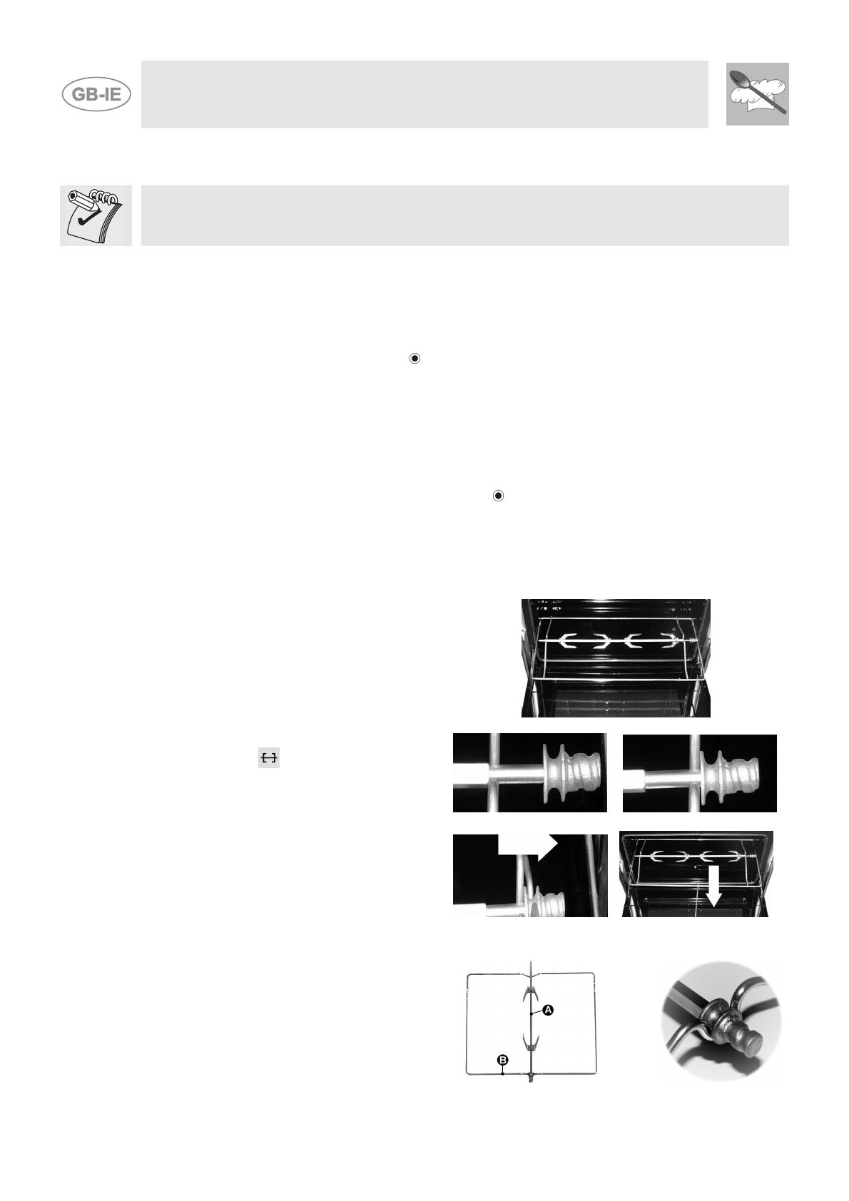
7.4 Use of the rotisserie (only on some models)
7.4.1 Using the rotisserie in cookers with maxi oven
Fit the supporting frame onto the second
runner up from the bottom so that the seat
to take the rod projects outside the oven.
Place the rod as shown in the diagram (1)
and push the frame into the oven until the
end of the rod reaches the hole in the
rotisserie motor. Now push the rotisserie rod
to the left until it reaches the position shown
in the diagram (2). To activate this function,
turn the switch to (
).
These operations must be carried out
with the oven switched off and cold.
When cooking is over, use the tool provided
to extract the rod from the hole (3) and
remove the frame (4) to bring the rotisserie
rod out of the oven cavity.
1
2
3
4
7.4.2 Using the rotisserie in cookers with standard ovens
Place the rotisserie frame “B” on the second
runners up from the bottom and insert the rod
A” in the hole in the back of the oven.
Instruction for the user
21
7.4.3 How to use the grill
Once the grill is lit, leave the oven to heat up for five minutes before placing the food inside.
Food should be flavoured and coated with oil or melted butter before cooking. An oven dish should be
used to contain the sauces.
The foods for cooking must be placed on the oven shelf, which is then placed on one of the runners
fitted in the various types of ovens, following the guidelines below:
FOOD RACK ON THE SHELF
Flat or thin meat
3
Rolled roast joints
2 – 3
Poultry
2 – 3
WARNING
Grilling processes must never last more than 60 minutes.
Keep the oven door closed during grilling.
To prevent hazardous overheating, the appliance's glass cover must always be raised
when using the oven or grill.
Accessible parts may be very hot during and after use of the grill; keep children well away
from the appliance.
During rotisserie cooking operations, one of the oven trays supplied with the cooker
should be placed on the bottom of the oven, on the bottom runners, to collect any grease
and fat produced.
When using the oven, remove all unused trays and racks from its interior.
7.5 Storage compartment (on some models only)
A storage compartment, accessible by pulling on the top edge
of the door, is located beneath the oven.
Never use it to store flammable materials such as rags, paper,
etc.; it is intended for storing the appliance's metal accessories
only.
Never open the storage compartment when the oven is on and still hot. The temperature inside may
be very high.
Instruction for the user
22
8 CLEANING AND MAINTENANCE
8.1 Cleaning stainless steel and enamelled versions
To maintain stainless steel in good condition it must be cleaned regularly after each use, once it has
cooled down.
8.1.1 Ordinary Daily Cleaning
To clean and preserve the stainless steel surfaces, always use only specific products that do not
contain abrasives or chlorine-based acids.
How to use: pour the product on a damp cloth and wipe the surface, rinse thoroughly and dry with a
soft cloth or deerskin.
8.1.2 Food stains or residues
Do not use metallic sponges or sharp scrapers: they will damage the surface.
Use normal non-abrasive products for steel, and a wooden or plastic tool if necessary.
Rinse thoroughly and dry with a soft cloth or deerskin.
Do not allow residues of sugary foods (such as jam) to set inside the oven. If left to set
for too long, they might damage the enamel lining of the oven.
8.2 Cleaning the cooking hob components
8.2.1 The glass cover
The cover can be removed from the hinges by lifting it upwards when it is open.
This makes cleaning easier.
If liquids are spilt on the closed cover, remove them thoroughly with a rag
before opening it.
8.2.2 Racks
Remove the racks and clean them in warm water with a non-abrasive detergent, taking care to
remove any incrustations. Replace them on the cooking hob.
Continuous contact of the racks with the flame can cause the paint near the hot areas to be altered.
This is completely natural and does not compromise the functionality of the component.
8.2.3 Burner caps and flame cap crowns
The caps and flame-spreader crowns are extractable to facilitate cleaning.
Wash them in hot water with non-abrasive detergent, taking care to
remove any incrustations, and wait until they are perfectly dry.
CAUTION: do not wash these components in a dishwasher.
The burners can be left to soak in hot water and detergent.
Replace the flame-spreader crowns, checking that they are positioned in
their housing with their respective caps, taking care that the flame-
spreader holes A correspond to the spark plugs and the thermocouples.
  • Page 1 1
  • Page 2 2
  • Page 3 3
  • Page 4 4
  • Page 5 5
  • Page 6 6
  • Page 7 7
  • Page 8 8
  • Page 9 9
  • Page 10 10
  • Page 11 11
  • Page 12 12
  • Page 13 13
  • Page 14 14
  • Page 15 15
  • Page 16 16
  • Page 17 17
  • Page 18 18
  • Page 19 19
  • Page 20 20
  • Page 21 21
  • Page 22 22

Smeg SX91VLSA Datasheet

Category
Cookers
Type
Datasheet

Smeg SX91VLSA is a versatile cooking appliance that combines a gas hob with an electric oven. The gas burners offer precise heat control for various cooking techniques, while the electric oven provides accurate temperature settings for baking and roasting. With its spacious interior and multiple functions, including grill and defrost, this appliance is well-equipped to handle a wide range of culinary tasks, making it a valuable addition to any kitchen.

Ask a question and I''ll find the answer in the document

Finding information in a document is now easier with AI