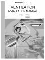
Thermador HPWB30FS/01 Installation guide
- Category
- Cooker hoods
- Type
- Installation guide
This manual is also suitable for
Page is loading ...

APPROVED FOR RESiDENTiAL APPLIANCES
FOR RESiDENTiAL USE ONLY
READ AND SAVE THESE iNSTRUCTiONS
PLEASE READ ENTIRE INSTRUCTIONS BEFORE PROCEEDING.
iNSTALLATiON MUST COMPLY WiTH ALL LOCAL CODES.
iMPORTANT: Save these instructions for the Local Electrical inspector's use.
iNSTALLER: Please leave these instructions with this unit for the owner.
OWNER: Please retain these instructions for future reference.
Safety Warning: Turn off power circuit at service panel and lock out panel, before wiring this appliance.
Requirement: 120 V AC, 60 Hz. 15 or 20 A Branch Circuit

IMPORTANT SAFETY INSTRUCTIONS
Read All Instructions Before Using the Appliance.
READ AND SAVE THESE INSTRUCTIONS
WA
TO REDUCE THE RISK OF FIRE, ELECTRIC
SHOCK, OR iNJURY TO PERSONS, OBSERVE
THE FOLLOWING:
A. Use this unit only in the manner intended by the
manufacturer. If you have questions, contact
the manufacturer.
B. Before servicing or cleaning the unit, switch
power off at service panel and lock service
panel disconnecting means to prevent power
from being switched on accidentally. When the
service disconnecting means cannot be locked,
securely fasten a prominent warning device,
such as a tag, to the service panel.
C. installation Work and Electrical Wiring Must Be
Done By Qualified Person(s) In Accordance
With All Applicable Codes & Standards,
including Fire-rated Construction.
D. Sufficient air is needed for proper combustion
and exhausting of gases through the flue
(chimney) of fuel burning equipment to prevent
back- drafting. Follow the heating equipment
manufacturers guideline and safety standards
such as those published by the National Fire
Protection Association (NFPA), the American
Society for Heating, Refrigeration and Air
Conditioning Engineers (ASHRAE), and the
local code authorities.
E. When cutting or drilling into wall or ceiling, do
not damage electrical wiring and other hidden
utilities.
F. Ducted systems must always be vented to the
outdoors.
CAUTION
FOR GENERAL VENTiLATiNG USE ONLY. DO
NOT USE TO EXHAUST HAZARDOUS OR
EXPLOSIVE MATERIALS OR VAPORS.
CAUTION
To reduce risk of fire and to properly exhaust
air, be sure to duct air outside - do not vent
exhaust air into spaces within walls, ceilings,
attics, crawl spaces, or garages.
WARNING
TO REDUCE THE RISK OF FIRE, USE ONLY
METAL DUCT WORK.
Install this hood in accordance with all
requirements specified.
WARNING
To Reduce The Risk of Fire or Electric Shock,
Do Not Use This Hood With Any External Solid
State Speed Control Device.
OPERATION
a. Always leave safety grills and filters in place.
Without these components, operating blowers
could catch onto hair, fingers and loose clothing.
The manufacturer declines all responsibility in the
event of failure to observe the instructions given
here for installation, maintenance and suitable use
of the product. The manufacturer further declines
all responsibility for injury due to negligence and
the warranty of the unit automatically expires due to
improper maintenance.
This unit is manufactured for indoor use only. Do not use this unit outdoors.

IMPORTANT SAFETY INSTRUCTIONS
Read All Instructions Before Using the Appliance.
READ AND SAVE THESE INSTRUCTIONS
Electrical requirements
IMPORTANT
Observe all governing codes and ordinances.
It is the customer's responsibility:
To contact a qualified electrical installer.
To assure thatthe electrical installation is adequate
and in conformance with National Electrical Code,
ANSI/NFPA 70 -- latest edition s-,or CSA Standards
C22.1-94, Canadian Electrical Code, Part land
C22.2 No.0-M91 - latest edition _-_-andall local
codes and ordinances.
If codes permit and a separate ground wire is used,
it is recommended that a qualified electrician
determine that the ground path is adequate.
Do notground to a gas pipe.
Check with a qualified electrician if you are not sure
range hood is properly grounded.
Do not have a fuse in the neutral or ground circuit.
IMPORTANT
Save Installation Instructions for electrical
inspector's use.
The range hood must be connected with copper
wire only.
The range hood should be connected directly to the
fused disconnect (or circuit breaker) box through
metal electrical conduit.
Wire sizes must conform to the requirements of the
National Electrical Code ANSI/NFPA 70--latest
edition s-,or CSA Standards C22.1-94, Canadian
Electrical Code Part 1 and C22.2 No. 0-M91 - latest
edition_-_-and all local codes and ordinances.
A U.L. - or C.S.A.- listed conduit connector must be
provided at each end of the power supply conduit
(at the range hood and at the junction box).
Copies of the standards listed may be obtained from:
National Fire Protection Association Batterymarch Park
Quincy, Massachusetts 02269
_CSA International 8501 East Pleasant Valley Road
Cleveland, Ohio 44131-5575
4

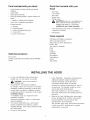
Parts Included with your Hood
• Hood Canopy Assembly with blower already
installed
• Grease filters
• Drip tray for each filter.
• Drip trays holding brakers + plastic wahers and
knobs
• 1Transition withback draft damper
• Use & Care / Installation Instructions
• Fittings bag with:
4 Washers
6 Drywall anchors
2 Hookswith regulating screws
6 ScrewsSX3S
4 Screws for transition
Optional accessory
Duct covers
Ductless recirculation kit available only for HPWB30
model.
Parts Not Included with your
Hood
• Duct Tape
• 1/2"Conduit
• Wire Nuts
• Round Duct.
• Wiring clamp
• _ OAUTION! Lamps are not supplied, use
ONLY 120 Volt, 50 Watt (maximum) S0°
halogen light made o r a GU10 base,
suitable for use in open luminarie.
• 4 #10 pan head wood screws for installation on
a bottom of a cabinet
3 prong plug
Tools required
Flat blade and Phillips screwdrivers
Pencil and tape measure
Metal snips (in some applications)
Electric drill
Saw (saber or keyhole)
Pliers
LeveI
Caulking
Flashlight
Wire stripper
Safety glasses
Gloves
Step ladder
INSTALLING THE HOOD
For the most efficient air flow exhaust, use a
straight run or as few elbows as possible.
_ CAUTION: Vent unittooutsideof
building, only.
Two people are necessaryfor installation.
On average 2 hours are necessary to complete
installation (without considering cut to be done
on wall and o r on cabinet, installation of ducts,
conduit and electrical connections to the mains).
installation steps:
11 installation steps are required for both
installation methods
Wall mount installation steps or in a Iternative
Cabinet installation
The hood is fitted with Screws and Drywal
Anchors suitable for most surfaces, consult a
Qualified Installer, check if they perfectly fitwith
your cabinet/wall.
Do not use flex ducting.
• COLD WEATHER installations should have an
additional backdraft damper installed to
minimize backward cold air flow and a
nonmetallic thermal break to minimize
conduction of outside temperatures as part of
the ductwork. The damper should be on the
cold air side of the thermal break.
The break should be as close as possible to
where the ducting enters the heated portion of
the house.
Make up air: Local building codes may require
the use of Make-UpAir Systems when using
Ducted Ventilation Systems greater than
specified CFM of air movement.
The specified CFM varies from location to location
Consult your HVAC professional f or specific
requirements in your area.

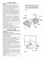
Typical installation
The height from the countertop to the bottom of the hood is 30" to 36".
These hoods are not recommended to be used over indoor grills.
1. Choose vent options
The hood is designed to be used for vertical discharge as shown below.
Note: see also Fig. 1-2-3 for Cabinet preparation.
Install a 1/2" conduit from the service panel long enough to reach the hood
once it is installed. Power supply must be rated for 120 VAC, 60Hz. 15 or 20 A.
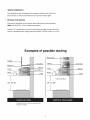
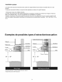
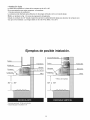
Examples of possible ducting
Ceiling
*Deflector
Lamp
Hood
T
30" to 36"
Transition
Blower
*Charcoal filters
Filter
Round duct
Ceiling
Lamp
--\
Hood
l * Charcoal filters
30" to 36"
1
Transition
Blower
Filter
Optional accessory- Ductlessrecirculationkit
Onlyfor 30" model

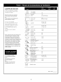
DUCT FITTINGS
Use this chart to compute maximum
permissable lengths for duct runs to
outdoors.
Note; Do not exceed maximum permissable
equivalent lengths!
Maximum recommended duct
length for these hoods: 150 feet
Flexible ducti ng:
If flexible metal ducting is used, all
the equivalent feet values in the table
should be doubled. The flexible
metal duct shou Id be straight and
smooth and extended as much as
possible.
Do NOT use flexible plastic ducting.
Note: Any home ventilation system, such as a
ventilation hood, may interrupt the proper flow of
combustion air and exhaust required by fireplaces,
gas furnaces, gas water heaters and other naturally
vented systems. To minimize the chance of interruption
of such naturally vented systems, follow the heating
equipment manufacturer's guidelines and safety
standards such as those published by NFPA and ASHRAE.
*Hoods are supplied with a 10"
round transition. A locally
supplied transition is required
for other sizes.
Note: Outlet on top of hood is
8-1/8" x 8".
qP
10" round
to 8" roun d
Round,
straight
3-1/4" x 10"
3-1/4" x 12 "
straight
go° elbow
Sft.
1ft.
(per foot
length)
1ft.
(per foot
length)
8" Dia. 17 ft.
1O"Dia. 24 ft .
45° elbow
8" Dia. lOft.
10" Dia. 14ft .
3-1/4" x 12" 15ft.
3-1/4" x 10" 14ft.
90° elbow
3-1/4" xlO" 8ft.
3-1/4" x12" 9ft.
45° elbow
3-1/4" x 10" 33 ft.
3-1/4" x 12" 36ft.
90° fiat elbow
10" round transition
to 3-1/4" x 10" or
3-1/4" x 12" 9 ft.
3-1/4" x 10" or
3-1/4" x 12" to
10" round transition 6 ft.
10" round to 3-1/4" xlO" 16ft.
3-1/4" x 12" transition 13 ft.
90° elbow
3-1/4" xlO" 9ft.
3-1/4"x12"t o10" round 8ft.
transiti on 90° elbow
Round
wall cap
with damper
3-1/4" x 10" 24ft.
3-1/4" x 12" wall cap 26ft.
with damper
8" Dia. 32 ft.
10" Dia.41 ft.
Round
roof cap
8" Dia. 44 ft.
10" Di a. 56 ft.
TotalDuctRun

For safety reasons, ducting should vent directly outdoors (not into an attic, underneath the house, into the
garage or into any enclosed space).
Keep duct runs as short and straight as possible.
Duct fittings (elbows and transitions) reduce air flow efficiency.
Back to back elbows and ,,S"turns give very poor delivery and are not recommended.
A short straight length of duct at the inlet of the remote blower gives the best delivery.
Transition to duct from the integral blower to remote duct transition as close as possible.
In order opreference, use:
1st. 10" round duct
2nd. 8round duct
3rd. 3-1/4" x 14" duct
4th. 7" round duct
5th. 3-1/4" x 10"duct
6th. 6" round duct
The use of flexible metal round duct should only be used when no other duct fitting exists. Limit use to short
lengths and do not crush when making corners.
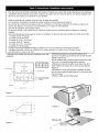
I. Prepare duct and conduit cut outs, see figures
I and 2 as needed.
Bottom of
Cabinet or
Soffit \
12"
Rear
Wall
I Model 30" 36" 48"
Cabinet Front X 2-3/4" 4-9/16"10-9/16
O O _ Vertical
=J _' _ Discharge
--'_/ ' _ /C_-J_I-' / vertical conduit
o.t,o°
CL
_Hood Width
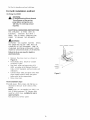
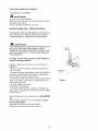
2. Assembly of the 10" transition:
The transition supplied with the hood mounts to
the top.
Do not install transition until hood is
fixed on cabinet or wall.
a. Place the transition piece over the hood
outlet and secure with 4 screws provided.
(Figure3)
b. Wrap all joints (metal transition and hood)
with duct tape for an airtight seal.
c. Remove tape holding damper.
Hood outlet
Figure 1
3_9!16, I
23-1/8"
11"
Figure 3
Transition
Figure 2
Screws (4)

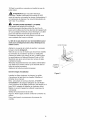
Wall Mount Installation
Note: see below if cabinet installation is preferred
3. After the hood installation height has been
determined draw a horizontal line at a distance
above the cooktop equal to the desired hood
installation height plus 7- 1/2". See also Figure 4a.
4. Find the centerline of the cooktop. Draw a
vertical line along this centerline up to the hori-
zontal line drawn in step 1 and draw a vertical
line right and left at a distance of 12-5/8" to
determine the mounting Iocationofthe
mounting hooks shipped with the hood.
5. Fit two mounting hooks on the wall to hang the
hood through the provided slots (2 wall
anchors + 2 hooks + 2 screws 5x35).
6. Run 10" Duct, long enough to reach the
transition once the hood has been installed plus
1 1/2" inch to connect ductwork. Fix Duct to
transition with screws and seal withtape.
7. Remove 1 of 2 knockouts and install 1/2"
conduit connector in j-box.
8. Hang the hood and adjust its position through
the screws on the hooks.
9. Fix the hood to 4 additional point, 2 on
upperside, 2 on lower side (use 4 wall anchors
+ 4washers + 4 screws 5x35.
Cabinet Installation:
Note: See above if wall mount installation is preferred
Note: Distances on Table 3.3
Find the centerline of the cabinet bottom. Draw a line
along this centerline from rear to front of the cabinet.
See also Figure 4b.
4. Draw two lines, one at a K distance from thewall,
the other one at a Z distance from theprevious line.
Mark 4 points, two along each line at a distance of
halfW from the center line, to determine the screw
locations.
5. Fit 4 screws on cabinet bottom do not tighten
completely but leave a space of about 1/2" from
cabinet bottom surface and head screws.
6. Run 10" Duct, long enough to reach the transition
once the hood has been installed plus1 1/2" inch for
connect ductwork.
7. Remove 1 of 2 knockouts and install 1/2"conduit
connector in j-box.
8. Hang the hood on screws through side slots provided
on hood top.Tighten the four screws. Note: If possible
fix the hood on the wall at 4 additional point (2 on
upper side, 2 on Iowerside).
9. From the inside of the cabinet attach the transition
on upper outlet.
HOOD WIDTH DIM. "W" DIM. "K" DIM. "Z"
30" 29- I/8" 2- I/2" 7- 1/16"
36" 35-I/16" 2- I/2" 7-I/16"
48" 47- 1/16" 2- I/2" 7- 1/16"
Table 3
Figure 4a Side slot x 4
Center Hole
Knockouts
(junction Z
w
.Top
location
Square
slot
7 1/2' t
bottom fixing
screws locations
© ©
wj
K
Hook for wall i _ Screw for
/installation == cabinet
_'_n 25 ,::3/16" n _ bottom
_ i __j__ _'_. installation
°,, 12 5/8"J 12 5/8" T _Adjusting
71/2" I "__ screw
Bottom of the Hood
Figure 4b

Fix Duct to transition and seal with tape.
For both installation method-
10.Wiring the HOOD:
WARNING:
To Avoid Electrical Shock Hazard
Turn off power at the service
panel before wiring this unit.
120 VAC, 15 or 20 Amp circuit
required.
ELECTRICAL GROUNDING INSTRUCTIONS
THIS APPLIANCE IS FITTED WITH AN
ELECTRICAL JUNCTION BOX WITH 3
WIRES, ONE OF WHICH (GREEN/YELLOW)
SERVES TO GROUND THE APPLIANCE.
_ WA RNING:
TO PROTECT YOU AGAINST ELECTRIC SHOCK,
THE GREENAND YELLOW WIRE MUST BE
CONNECTEDTO THE GROUNDING WIRE IN
YOURHOME ELECTRICALSYSTEM,AND IT MUST
UNDERNO CIRCUNSTANCESBECUTORREMOVED.
Failure to do so can result in death or
electrical shock.
• Remove the j-box cover as shown in
Figure 5.
• If notalready done, install 1/2" conduit
connector in j-box.
Run black, white, and green wires (#14
AWG) according to the National Electrical
Code or CSA Standards and local codes and
ordinances.
Connect black, white, and green wires from
power supply to black, white, and green/
yellow wires in j-box respectively.
• Close j-box cover.
Final installation steps
11.Install grease filters, lamps and drip trays as
described in the Care & Use section of this
manual.
Note: Lamps are not supplied, use ONLY 120
Volt, S0 Watt (maximum) 50° halogen light
made fora GU10 base, suitable for use in
open luminarie.
Turn power on at service panel.
Power supply conduit
fJ["
From
control
pa nel
Figure 5
10
Page is loading ...
Page is loading ...
Page is loading ...
Page is loading ...
Page is loading ...
Page is loading ...
Page is loading ...
Page is loading ...
Page is loading ...
Page is loading ...
Page is loading ...
Page is loading ...
Page is loading ...
Page is loading ...
Page is loading ...
Page is loading ...
Page is loading ...

APPROVED FOR RESiDENTiAL APPLIANCES
FOR RESiDENTiAL USE ONLY
READ AND SAVE THESE iNSTRUCTiONS
PLEASE READ ENTIRE INSTRUCTIONS BEFORE PROCEEDING.
iNSTALLATiON MUST COMPLY WiTH ALL LOCAL CODES.
iMPORTANT: Save these instructions for the Local Electrical inspector's use.
iNSTALLER: Please leave these instructions with this unit for the owner.
OWNER: Please retain these instructions for future reference.
Safety Warning: Turn off power circuit at service panel and lock out panel, before wiring this appliance.
Requirement: 120 V AC, 60 Hz. 15 or 20 A Branch Circuit

IMPORTANT SAFETY INSTRUCTIONS
Read All Instructions Before Using the Appliance.
READ AND SAVE THESE INSTRUCTIONS
WA
TO REDUCE THE RISK OF FIRE, ELECTRIC
SHOCK, OR iNJURY TO PERSONS, OBSERVE
THE FOLLOWING:
A. Use this unit only in the manner intended by the
manufacturer. If you have questions, contact
the manufacturer.
B. Before servicing or cleaning the unit, switch
power off at service panel and lock service
panel disconnecting means to prevent power
from being switched on accidentally. When the
service disconnecting means cannot be locked,
securely fasten a prominent warning device,
such as a tag, to the service panel.
C. installation Work and Electrical Wiring Must Be
Done By Qualified Person(s) In Accordance
With All Applicable Codes & Standards,
including Fire-rated Construction.
D. Sufficient air is needed for proper combustion
and exhausting of gases through the flue
(chimney) of fuel burning equipment to prevent
back- drafting. Follow the heating equipment
manufacturers guideline and safety standards
such as those published by the National Fire
Protection Association (NFPA), the American
Society for Heating, Refrigeration and Air
Conditioning Engineers (ASHRAE), and the
local code authorities.
E. When cutting or drilling into wall or ceiling, do
not damage electrical wiring and other hidden
utilities.
F. Ducted systems must always be vented to the
outdoors.
CAUTION
FOR GENERAL VENTiLATiNG USE ONLY. DO
NOT USE TO EXHAUST HAZARDOUS OR
EXPLOSIVE MATERIALS OR VAPORS.
CAUTION
To reduce risk of fire and to properly exhaust
air, be sure to duct air outside - do not vent
exhaust air into spaces within walls, ceilings,
attics, crawl spaces, or garages.
WARNING
TO REDUCE THE RISK OF FIRE, USE ONLY
METAL DUCT WORK.
Install this hood in accordance with all
requirements specified.
WARNING
To Reduce The Risk of Fire or Electric Shock,
Do Not Use This Hood With Any External Solid
State Speed Control Device.
OPERATION
a. Always leave safety grills and filters in place.
Without these components, operating blowers
could catch onto hair, fingers and loose clothing.
The manufacturer declines all responsibility in the
event of failure to observe the instructions given
here for installation, maintenance and suitable use
of the product. The manufacturer further declines
all responsibility for injury due to negligence and
the warranty of the unit automatically expires due to
improper maintenance.
This unit is manufactured for indoor use only. Do not use this unit outdoors.

IMPORTANT SAFETY INSTRUCTIONS
Read All Instructions Before Using the Appliance.
READ AND SAVE THESE INSTRUCTIONS
Electrical requirements
IMPORTANT
Observe all governing codes and ordinances.
It is the customer's responsibility:
To contact a qualified electrical installer.
To assure thatthe electrical installation is adequate
and in conformance with National Electrical Code,
ANSI/NFPA 70 -- latest edition s-,or CSA Standards
C22.1-94, Canadian Electrical Code, Part land
C22.2 No.0-M91 - latest edition _-_-andall local
codes and ordinances.
If codes permit and a separate ground wire is used,
it is recommended that a qualified electrician
determine that the ground path is adequate.
Do notground to a gas pipe.
Check with a qualified electrician if you are not sure
range hood is properly grounded.
Do not have a fuse in the neutral or ground circuit.
IMPORTANT
Save Installation Instructions for electrical
inspector's use.
The range hood must be connected with copper
wire only.
The range hood should be connected directly to the
fused disconnect (or circuit breaker) box through
metal electrical conduit.
Wire sizes must conform to the requirements of the
National Electrical Code ANSI/NFPA 70--latest
edition s-,or CSA Standards C22.1-94, Canadian
Electrical Code Part 1 and C22.2 No. 0-M91 - latest
edition_-_-and all local codes and ordinances.
A U.L. - or C.S.A.- listed conduit connector must be
provided at each end of the power supply conduit
(at the range hood and at the junction box).
Copies of the standards listed may be obtained from:
National Fire Protection Association Batterymarch Park
Quincy, Massachusetts 02269
_CSA International 8501 East Pleasant Valley Road
Cleveland, Ohio 44131-5575
4

Parts Included with your Hood
• Hood Canopy Assembly with blower already
installed
• Grease filters
• Drip tray for each filter.
• Drip trays holding brakers + plastic wahers and
knobs
• 1Transition withback draft damper
• Use & Care / Installation Instructions
• Fittings bag with:
4 Washers
6 Drywall anchors
2 Hookswith regulating screws
6 ScrewsSX3S
4 Screws for transition
Optional accessory
Duct covers
Ductless recirculation kit available only for HPWB30
model.
Parts Not Included with your
Hood
• Duct Tape
• 1/2"Conduit
• Wire Nuts
• Round Duct.
• Wiring clamp
• _ OAUTION! Lamps are not supplied, use
ONLY 120 Volt, 50 Watt (maximum) S0°
halogen light made o r a GU10 base,
suitable for use in open luminarie.
• 4 #10 pan head wood screws for installation on
a bottom of a cabinet
3 prong plug
Tools required
Flat blade and Phillips screwdrivers
Pencil and tape measure
Metal snips (in some applications)
Electric drill
Saw (saber or keyhole)
Pliers
LeveI
Caulking
Flashlight
Wire stripper
Safety glasses
Gloves
Step ladder
INSTALLING THE HOOD
For the most efficient air flow exhaust, use a
straight run or as few elbows as possible.
_ CAUTION: Vent unittooutsideof
building, only.
Two people are necessaryfor installation.
On average 2 hours are necessary to complete
installation (without considering cut to be done
on wall and o r on cabinet, installation of ducts,
conduit and electrical connections to the mains).
installation steps:
11 installation steps are required for both
installation methods
Wall mount installation steps or in a Iternative
Cabinet installation
The hood is fitted with Screws and Drywal
Anchors suitable for most surfaces, consult a
Qualified Installer, check if they perfectly fitwith
your cabinet/wall.
Do not use flex ducting.
• COLD WEATHER installations should have an
additional backdraft damper installed to
minimize backward cold air flow and a
nonmetallic thermal break to minimize
conduction of outside temperatures as part of
the ductwork. The damper should be on the
cold air side of the thermal break.
The break should be as close as possible to
where the ducting enters the heated portion of
the house.
Make up air: Local building codes may require
the use of Make-UpAir Systems when using
Ducted Ventilation Systems greater than
specified CFM of air movement.
The specified CFM varies from location to location
Consult your HVAC professional f or specific
requirements in your area.

Typical installation
The height from the countertop to the bottom of the hood is 30" to 36".
These hoods are not recommended to be used over indoor grills.
1. Choose vent options
The hood is designed to be used for vertical discharge as shown below.
Note: see also Fig. 1-2-3 for Cabinet preparation.
Install a 1/2" conduit from the service panel long enough to reach the hood
once it is installed. Power supply must be rated for 120 VAC, 60Hz. 15 or 20 A.
Examples of possible ducting
Ceiling
*Deflector
Lamp
Hood
T
30" to 36"
Transition
Blower
*Charcoal filters
Filter
Round duct
Ceiling
Lamp
--\
Hood
l * Charcoal filters
30" to 36"
1
Transition
Blower
Filter
Optional accessory- Ductlessrecirculationkit
Onlyfor 30" model

DUCT FITTINGS
Use this chart to compute maximum
permissable lengths for duct runs to
outdoors.
Note; Do not exceed maximum permissable
equivalent lengths!
Maximum recommended duct
length for these hoods: 150 feet
Flexible ducti ng:
If flexible metal ducting is used, all
the equivalent feet values in the table
should be doubled. The flexible
metal duct shou Id be straight and
smooth and extended as much as
possible.
Do NOT use flexible plastic ducting.
Note: Any home ventilation system, such as a
ventilation hood, may interrupt the proper flow of
combustion air and exhaust required by fireplaces,
gas furnaces, gas water heaters and other naturally
vented systems. To minimize the chance of interruption
of such naturally vented systems, follow the heating
equipment manufacturer's guidelines and safety
standards such as those published by NFPA and ASHRAE.
*Hoods are supplied with a 10"
round transition. A locally
supplied transition is required
for other sizes.
Note: Outlet on top of hood is
8-1/8" x 8".
qP
10" round
to 8" roun d
Round,
straight
3-1/4" x 10"
3-1/4" x 12 "
straight
go° elbow
Sft.
1ft.
(per foot
length)
1ft.
(per foot
length)
8" Dia. 17 ft.
1O"Dia. 24 ft .
45° elbow
8" Dia. lOft.
10" Dia. 14ft .
3-1/4" x 12" 15ft.
3-1/4" x 10" 14ft.
90° elbow
3-1/4" xlO" 8ft.
3-1/4" x12" 9ft.
45° elbow
3-1/4" x 10" 33 ft.
3-1/4" x 12" 36ft.
90° fiat elbow
10" round transition
to 3-1/4" x 10" or
3-1/4" x 12" 9 ft.
3-1/4" x 10" or
3-1/4" x 12" to
10" round transition 6 ft.
10" round to 3-1/4" xlO" 16ft.
3-1/4" x 12" transition 13 ft.
90° elbow
3-1/4" xlO" 9ft.
3-1/4"x12"t o10" round 8ft.
transiti on 90° elbow
Round
wall cap
with damper
3-1/4" x 10" 24ft.
3-1/4" x 12" wall cap 26ft.
with damper
8" Dia. 32 ft.
10" Dia.41 ft.
Round
roof cap
8" Dia. 44 ft.
10" Di a. 56 ft.
TotalDuctRun

For safety reasons, ducting should vent directly outdoors (not into an attic, underneath the house, into the
garage or into any enclosed space).
Keep duct runs as short and straight as possible.
Duct fittings (elbows and transitions) reduce air flow efficiency.
Back to back elbows and ,,S"turns give very poor delivery and are not recommended.
A short straight length of duct at the inlet of the remote blower gives the best delivery.
Transition to duct from the integral blower to remote duct transition as close as possible.
In order opreference, use:
1st. 10" round duct
2nd. 8round duct
3rd. 3-1/4" x 14" duct
4th. 7" round duct
5th. 3-1/4" x 10"duct
6th. 6" round duct
The use of flexible metal round duct should only be used when no other duct fitting exists. Limit use to short
lengths and do not crush when making corners.
I. Prepare duct and conduit cut outs, see figures
I and 2 as needed.
Bottom of
Cabinet or
Soffit \
12"
Rear
Wall
I Model 30" 36" 48"
Cabinet Front X 2-3/4" 4-9/16"10-9/16
O O _ Vertical
=J _' _ Discharge
--'_/ ' _ /C_-J_I-' / vertical conduit
o.t,o°
CL
_Hood Width
2. Assembly of the 10" transition:
The transition supplied with the hood mounts to
the top.
Do not install transition until hood is
fixed on cabinet or wall.
a. Place the transition piece over the hood
outlet and secure with 4 screws provided.
(Figure3)
b. Wrap all joints (metal transition and hood)
with duct tape for an airtight seal.
c. Remove tape holding damper.
Hood outlet
Figure 1
3_9!16, I
23-1/8"
11"
Figure 3
Transition
Figure 2
Screws (4)

Wall Mount Installation
Note: see below if cabinet installation is preferred
3. After the hood installation height has been
determined draw a horizontal line at a distance
above the cooktop equal to the desired hood
installation height plus 7- 1/2". See also Figure 4a.
4. Find the centerline of the cooktop. Draw a
vertical line along this centerline up to the hori-
zontal line drawn in step 1 and draw a vertical
line right and left at a distance of 12-5/8" to
determine the mounting Iocationofthe
mounting hooks shipped with the hood.
5. Fit two mounting hooks on the wall to hang the
hood through the provided slots (2 wall
anchors + 2 hooks + 2 screws 5x35).
6. Run 10" Duct, long enough to reach the
transition once the hood has been installed plus
1 1/2" inch to connect ductwork. Fix Duct to
transition with screws and seal withtape.
7. Remove 1 of 2 knockouts and install 1/2"
conduit connector in j-box.
8. Hang the hood and adjust its position through
the screws on the hooks.
9. Fix the hood to 4 additional point, 2 on
upperside, 2 on lower side (use 4 wall anchors
+ 4washers + 4 screws 5x35.
Cabinet Installation:
Note: See above if wall mount installation is preferred
Note: Distances on Table 3.3
Find the centerline of the cabinet bottom. Draw a line
along this centerline from rear to front of the cabinet.
See also Figure 4b.
4. Draw two lines, one at a K distance from thewall,
the other one at a Z distance from theprevious line.
Mark 4 points, two along each line at a distance of
halfW from the center line, to determine the screw
locations.
5. Fit 4 screws on cabinet bottom do not tighten
completely but leave a space of about 1/2" from
cabinet bottom surface and head screws.
6. Run 10" Duct, long enough to reach the transition
once the hood has been installed plus1 1/2" inch for
connect ductwork.
7. Remove 1 of 2 knockouts and install 1/2"conduit
connector in j-box.
8. Hang the hood on screws through side slots provided
on hood top.Tighten the four screws. Note: If possible
fix the hood on the wall at 4 additional point (2 on
upper side, 2 on Iowerside).
9. From the inside of the cabinet attach the transition
on upper outlet.
HOOD WIDTH DIM. "W" DIM. "K" DIM. "Z"
30" 29- I/8" 2- I/2" 7- 1/16"
36" 35-I/16" 2- I/2" 7-I/16"
48" 47- 1/16" 2- I/2" 7- 1/16"
Table 3
Figure 4a Side slot x 4
Center Hole
Knockouts
(junction Z
w
.Top
location
Square
slot
7 1/2' t
bottom fixing
screws locations
© ©
wj
K
Hook for wall i _ Screw for
/installation == cabinet
_'_n 25 ,::3/16" n _ bottom
_ i __j__ _'_. installation
°,, 12 5/8"J 12 5/8" T _Adjusting
71/2" I "__ screw
Bottom of the Hood
Figure 4b

Fix Duct to transition and seal with tape.
For both installation method-
10.Wiring the HOOD:
WARNING:
To Avoid Electrical Shock Hazard
Turn off power at the service
panel before wiring this unit.
120 VAC, 15 or 20 Amp circuit
required.
ELECTRICAL GROUNDING INSTRUCTIONS
THIS APPLIANCE IS FITTED WITH AN
ELECTRICAL JUNCTION BOX WITH 3
WIRES, ONE OF WHICH (GREEN/YELLOW)
SERVES TO GROUND THE APPLIANCE.
_ WA RNING:
TO PROTECT YOU AGAINST ELECTRIC SHOCK,
THE GREENAND YELLOW WIRE MUST BE
CONNECTEDTO THE GROUNDING WIRE IN
YOURHOME ELECTRICALSYSTEM,AND IT MUST
UNDERNO CIRCUNSTANCESBECUTORREMOVED.
Failure to do so can result in death or
electrical shock.
• Remove the j-box cover as shown in
Figure 5.
• If notalready done, install 1/2" conduit
connector in j-box.
Run black, white, and green wires (#14
AWG) according to the National Electrical
Code or CSA Standards and local codes and
ordinances.
Connect black, white, and green wires from
power supply to black, white, and green/
yellow wires in j-box respectively.
• Close j-box cover.
Final installation steps
11.Install grease filters, lamps and drip trays as
described in the Care & Use section of this
manual.
Note: Lamps are not supplied, use ONLY 120
Volt, S0 Watt (maximum) 50° halogen light
made fora GU10 base, suitable for use in
open luminarie.
Turn power on at service panel.
Power supply conduit
fJ["
From
control
panel
Figure 5
10
Page is loading ...
Page is loading ...
Page is loading ...
Page is loading ...
Page is loading ...
Page is loading ...
Page is loading ...
Page is loading ...
Page is loading ...
Page is loading ...
Page is loading ...
Page is loading ...
Page is loading ...
Page is loading ...
Page is loading ...
Page is loading ...
-
 1
1
-
 2
2
-
 3
3
-
 4
4
-
 5
5
-
 6
6
-
 7
7
-
 8
8
-
 9
9
-
 10
10
-
 11
11
-
 12
12
-
 13
13
-
 14
14
-
 15
15
-
 16
16
-
 17
17
-
 18
18
-
 19
19
-
 20
20
-
 21
21
-
 22
22
-
 23
23
-
 24
24
-
 25
25
-
 26
26
-
 27
27
-
 28
28
-
 29
29
-
 30
30
-
 31
31
-
 32
32
-
 33
33
-
 34
34
-
 35
35
-
 36
36
-
 37
37
-
 38
38
-
 39
39
-
 40
40
-
 41
41
-
 42
42
-
 43
43
-
 44
44
-
 45
45
-
 46
46
-
 47
47
-
 48
48
-
 49
49
-
 50
50
-
 51
51
-
 52
52


Thermador HPWB30FS/01 Installation guide
- Category
- Cooker hoods
- Type
- Installation guide
- This manual is also suitable for
Ask a question and I''ll find the answer in the document
Finding information in a document is now easier with AI
in other languages
Related papers
-
Thermador HMWB36FS/01 Installation guide
-
Thermador HPWB30FS Installation guide
-
-
Thermador HPWB36FS Installation guide
-
-
-
-
-
-
Other documents
-
Bosch DPH36652UC/01 Installation guide
-
Bosch DPH30652UC Installation guide
-
-
-
 arietta PRO001MX36 Installation guide
-
-
Broan 463623 Owner's manual
-
Broan F403023 Installation guide
-
Broan F403023 User manual
-
Broan-NuTone F403023 User manual
