SUPER MICRO Computer H8QM3-2 User manual
- Category
- Server/workstation motherboards
- Type
- User manual
This manual is also suitable for

H8QM3-2
H8QMi-2
USER’S MANUAL
Revision 1.1a
SUPER
®

Manual Revision 1.1a
Release Date: December 4, 2009
Unless you request and receive written permission from Super Micro Computer, Inc., you may not
copy any part of this document.
Information in this document is subject to change without notice. Other products and companies
referred to herein are trademarks or registered trademarks of their respective companies or mark
holders.
Copyright © 2009 by Super Micro Computer, Inc.
All rights reserved.
Printed in the United States of America
The information in this User’s Manual has been carefully reviewed and is believed to be accurate.
The vendor assumes no responsibility for any inaccuracies that may be contained in this document,
makes no commitment to update or to keep current the information in this manual, or to notify any
person or organization of the updates. Please Note: For the most up-to-date version of this
manual, please see our web site at www.supermicro.com.
Super Micro Computer, Inc. ("Supermicro") reserves the right to make changes to the product
described in this manual at any time and without notice. This product, including software, if any,
and documentation may not, in whole or in part, be copied, photocopied, reproduced, translated or
reduced to any medium or machine without prior written consent.
IN NO EVENT WILL SUPERMICRO BE LIABLE FOR DIRECT, INDIRECT, SPECIAL, INCIDENTAL,
SPECULATIVE OR CONSEQUENTIAL DAMAGES ARISING FROM THE USE OR INABILITY TO
USE THIS PRODUCT OR DOCUMENTATION, EVEN IF ADVISED OF THE POSSIBILITY OF
SUCH DAMAGES. IN PARTICULAR, SUPERMICRO SHALL NOT HAVE LIABILITY FOR ANY
HARDWARE, SOFTWARE, OR DATA STORED OR USED WITH THE PRODUCT, INCLUDING THE
COSTS OF REPAIRING, REPLACING, INTEGRATING, INSTALLING OR RECOVERING SUCH
HARDWARE, SOFTWARE, OR DATA.
Any disputes arising between manufacturer and customer shall be governed by the laws of Santa
Clara County in the State of California, USA. The State of California, County of Santa Clara shall
be the exclusive venue for the resolution of any such disputes. Super Micro's total liability for
all claims will not exceed the price paid for the hardware product.
FCC Statement: This equipment has been tested and found to comply with the limits for a Class
A digital device pursuant to Part 15 of the FCC Rules. These limits are designed to provide
reasonable protection against harmful interference when the equipment is operated in a commercial
environment. This equipment generates, uses, and can radiate radio frequency energy and, if not
installed and used in accordance with the manufacturer’s instruction manual, may cause harmful
interference with radio communications. Operation of this equipment in a residential area is likely
to cause harmful interference, in which case you will be required to correct the interference at your
own expense.
California Best Management Practices Regulations for Perchlorate Materials: This Perchlorate
warning applies only to products containing CR (Manganese Dioxide) Lithium coin cells. “Perchlorate
Material-special handling may apply. See www.dtsc.ca.gov/hazardouswaste/perchlorate”
WARNING: Handling of lead solder materials used in this
product may expose you to lead, a chemical known to
the State of California to cause birth defects and other
reproductive harm.

Preface
iii
Preface
About This Manual
This manual is written for system integrators, PC technicians and
knowledgeable PC users. It provides information for the installation and use of the
H8QM3-2/H8QMi-2 serverboard. The H8QM3-2/H8QMi-2 is based on the nVidia®
MCP55 Pro and IO55 chipset and supports two or four AMD Opteron Socket F
type 8000 series processors and up to 256 GB of DDR2-800/667/533 registered
ECC SDRAM.
Please refer to the serverboard specifi cations pages on our web site for updates on
supported processors (http://www.supermicro.com/aplus/). This product is intended
to be professionally installed.
Manual Organization
Chapter 1 includes a checklist of what should be included in your serverboard
box, describes the features, specifi cations and performance of the serverboard and
provides detailed information about the chipset.
Chapter 2 begins with instructions on handling static-sensitive devices. Read this
chapter when installing the processor(s) and memory modules and when installing
the serverboard in a chassis. Also refer to this chapter to connect the fl oppy and
hard disk drives, the parallel and serial ports, the mouse and keyboard and the
twisted wires for the power and reset buttons and the system LEDs.
If you encounter any problems, see Chapter 3, which describes troubleshooting
procedures for the video, the memory and the setup confi guration stored in CMOS.
For quick reference, a general FAQ (Frequently Asked Questions) section is pro-
vided. Instructions are also included for contacting technical support. In addition,
you can visit our web site for more detailed information.
Chapter 4 includes an introduction to BIOS and provides detailed information on
running the CMOS Setup utility.
Appendix A lists BIOS Error Beep Codes.
Appendix B lists BIOS POST Checkpoint Codes.

H8QM3-2/H8QMi-2 User’s Manual
Table of Contents
Chapter 1: Introduction
1-1 Overview ......................................................................................................... 1-1
Checklist .................................................................................................... 1-1
Contacting Supermicro ............................................................................. 1-2
H8QM3-2 Image ....................................................................................... 1-3
H8QM3-2/H8QMi-2 Serverboard Layout ................................................... 1-4
H8QM3-2/H8QMi-2 Quick Reference ........................................................ 1-5
Serverboard Features .............................................................................. 1-6
Chipset: System Block Diagram................................................................ 1-8
1-2 Chipset Overview ........................................................................................... 1-9
1-3 PC Health Monitoring ................................................................................... 1-10
1-4 Power Confi guration Settings ....................................................................... 1-10
1-5 Power Supply ............................................................................................... 1-12
1-6 Super I/O ........................................................................................................1-12
Chapter 2: Installation
2-1 Static-Sensitive Devices ................................................................................. 2-1
2-2 Processor and Heatsink Installation ............................................................... 2-2
2-3 Mounting the Serverboard into a Chassis ...................................................... 2-4
2-4 Installing Memory ........................................................................................... 2-4
2-5 I/O Port and Control Panel Connections ........................................................ 2-6
2-6 Connector Defi nitions ..................................................................................... 2-7
ATX Power Connector .............................................................................. 2-7
Processor Power Connectors .................................................................. 2-7
NMI Button ............................................................................................... 2-7
Power LED ............................................................................................... 2-7
HDD LED ................................................................................................ 2-8
NIC1 LED ................................................................................................. 2-8
NIC2 LED ................................................................................................. 2-8
Overheat/Fan Fail LED ............................................................................ 2-8
Power Fail LED ........................................................................................ 2-8
Reset Button ............................................................................................ 2-9
Power Button ............................................................................................ 2-9
Universal Serial Bus Ports ....................................................................... 2-9
USB Headers ........................................................................................... 2-9
Serial Ports ............................................................................................. 2-10
Fan Headers .......................................................................................... 2-10
iv

v
Table of Contents
Overheat LED ........................................................................................ 2-10
Power LED/Speaker ............................................................................... 2-10
JLAN1/2 (Ethernet Ports) ....................................................................... 2-11
ATX PS/2 Keyboard/Mouse Ports .......................................................... 2-11
Chassis Intrusion .................................................................................... 2-11
Wake-On-LAN ........................................................................................ 2-11
I
2
C Header .............................................................................................. 2-11
Wake-On-Ring ........................................................................................ 2-12
Compact Flash Power Headers ............................................................. 2-12
3-SGPIO1/3-SGPIO2 ............................................................................. 2-12
T-SGPIO1/T-SGPIO2 ............................................................................. 2-12
2-7 Jumper Settings ............................................................................................ 2-13
Explanation of Jumpers ......................................................................... 2-13
CMOS Clear ........................................................................................... 2-13
VGA Enable/Disable ............................................................................... 2-14
JLAN Enable/Disable ............................................................................. 2-14
I
2
C to PCI-X Slots .................................................................................. 2-14
I
2
C to PCI-E Slots .................................................................................. 2-14
Compact Flash Master/Slave ................................................................. 2-14
Watch Dog Enable/Disable ..................................................................... 2-15
PCI-X Slot Speed ................................................................................... 2-15
SAS RAID Select ................................................................................... 2-16
2-8 Onboard Indicators ....................................................................................... 2-16
JLAN1/JLAN2 LEDs ............................................................................... 2-16
Onboard Power LED .............................................................................. 2-16
SAS Activity LED .................................................................................... 2-16
2-9 Floppy, IDE SATA and SAS Drive Connections ........................................... 2-17
Floppy Connector ................................................................................... 2-17
IDE Connector ........................................................................................ 2-18
SATA Ports ............................................................................................. 2-18
SAS Ports ............................................................................................... 2-19
SIMLC (IPMI) Slot .................................................................................. 2-19
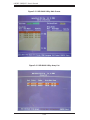
2-10 Enabling SATA RAID .................................................................................... 2-20
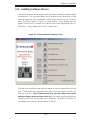
2-11 Installing Software Drivers ............................................................................ 2-23
Chapter 3: Troubleshooting
3-1 Troubleshooting Procedures ........................................................................... 3-1
Before Power On ..................................................................................... 3-1
No Power ................................................................................................. 3-1

H8QM3-2/H8QMi-2 User’s Manual
vi
Memory Errors ......................................................................................... 3-2
Losing the System’s Setup Confi guration ................................................ 3-2
3-2 Technical Support Procedures ........................................................................ 3-2
3-3 Frequently Asked Questions ........................................................................... 3-3
3-4 Returning Merchandise for Service ................................................................ 3-4
Chapter 4: BIOS
4-1 Introduction ..................................................................................................... 4-1
4-2 Main Menu ...................................................................................................... 4-2
4-3 Advanced Settings Menu ............................................................................... 4-2
4-4 Boot Menu .................................................................................................... 4-16
4-5 Security Menu ............................................................................................... 4-17
4-6 Exit Menu ...................................................................................................... 4-18
Appendices:
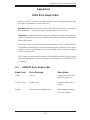
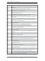
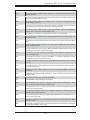
Appendix A: BIOS Error Beep Codes
Appendix B: BIOS POST Checkpoint Codes

Chapter 1: Introduction
1-1
Chapter 1
Introduction
1-1 Overview
Checklist
Congratulations on purchasing your computer serverboard from an acknowledged
leader in the industry. Our boards are designed with the utmost attention to detail
to provide you with the highest standards in quality and performance.
Please check that the following items have all been included with your serverboard.
If anything listed here is damaged or missing, contact your retailer.
Included with retail box only
One (1) H8QM3-2/H8QMi-2 serverboard
One (1) IDE cable (CBL-036L-03)
One (1) fl oppy cable (CBL-022L)
One (1) COM port cable (CBL-010L)
Eight (8) SATA cables (CBL-044L): H8QM3-2 only
Six (6) SATA cables (CBL-044L): H8QMi-2 only
One (1) I/O shield (CSE-PT55L)
One (1) CD containing drivers and utilities

1-2
H8QM3-2/H8QMi-2 User’s Manual
Contacting Supermicro
Headquarters
Address: Super Micro Computer, Inc.
980 Rock Ave.
San Jose, CA 95131 U.S.A.
Tel: +1 (408) 503-8000
Fax: +1 (408) 503-8008
Web Site: www.supermicro.com
Europe
Address: Super Micro Computer B.V.
Het Sterrenbeeld 28, 5215 ML
's-Hertogenbosch, The Netherlands
Tel: +31 (0) 73-6400390
Fax: +31 (0) 73-6416525
Asia-Pacifi c
Address: Super Micro Computer, Inc.
4F, No. 232-1, Liancheng Rd.
Chung-Ho 235, Taipei, Taiwan, R.O.C.
Tel: +886-(2) 8226-3990
Fax: +886-(2) 8226-3991
Web Site: www.supermicro.com.tw
Technical Support:
Email: [email protected]
Tel: 886-2-8228-1366, ext.132 or 139

Chapter 1: Introduction
1-3
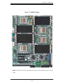
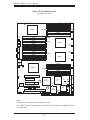
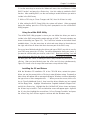
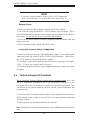
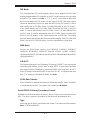
Figure 1-1. H8QM3-2 Image
Note: the H8QMi-2 has the same layout but does not include SAS ports or compo-
nents.

1-4
H8QM3-2/H8QMi-2 User’s Manual
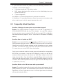
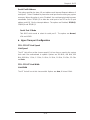
Notes:
Jumpers not indicated are for test purposes only.
The H8QMi-2 has the same layout as the H8QM3-2 but does not include SAS ports
or components.
Figure 1-2. Serverboard Layout
(not drawn to scale)
SUPER H8QM3-2
CPU 4
CPU 2
CPU 1
CPU 3
DIMMC 4A
DIMMC 4B
DIMMC 3A
DIMMC 3B
DIMMC 2A
DIMMC 2B
DIMMC 1A
DIMMD 1B
DIMMD 1A
DIMMD 2B
DIMMD 2A
DIMMD 3B
DIMMD 3A
DIMMD 4B
DIMMD 4A
DIMMA 4A
DIMMA 4B
DIMMA 3A
DIMMA 3B
DIMMA 2A
DIMMA 2B
DIMMA 1A
DIMMA 1B
DIMMB 1B
DIMMB 1A
DIMMB 2B
DIMMB 2A
DIMMB 3B
DIMMB 3A
DIMMB 4B
DIMMB 4A
Kybd/
Mouse
JLAN1
USB0/1
COM1
VGA
JLAN2
ATI
ES 1000
SIMLC
Slot #1: PCI-X 133/100 MHz
Slot #2: PCI-Express x16
Slot #3: PCI-Express x8
Slot #4: PCI-Express x4
Slot #5: PCI-Express x16
COM2
SATA0
SATA1
SATA2
SATA3
SATA4
SATA5
nVidia
MCP55 Pro
nVidia
IO55
BIOS
NEC
uPD720404
LSI
1068E
SAS0
SAS1
SAS2
SAS3
SAS4
SAS5
SAS6
SAS7
IDEFLOPPY
J1B1
JPW1JPW2
Battery
JPG1
JPL1
I Button
JPX1A
JWOL
USB2/3
JPX2A
3-SGPIO2 3-SGPIO1
FAN9
FAN8/
CPU3
FAN7/
CPU4
FAN3/
CPU2
FAN2
FAN1
Speaker
JOH1
JF1
JD1
FAN4/
CPU1
FAN5
FAN6
JPI
2
C
JWF1
LES1
JCF1
JL1
T-SGPIO2
T-SGPIO1
JWOR
JPS1
JWD
JI
2
C1
JI
2
C2
JI
2
C4
JI
2
C3
CPU4 DIMMs
CPU3 DIMMs
CPU2 DIMMs
CPU1 DIMMs
JBT1
DIMMA 1B

Chapter 1: Introduction
1-5
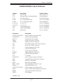
H8QM3-2/H8QMi-2 Quick Reference
Jumpers Description Default Setting
JBT1 CMOS Clear (See Section 2-7)
JCF1 Compact Flash Card Master/Slave Closed (Master)
JPS1* SAS RAID Select Closed (SR RAID)
JPX1A PCI-X Slot Speed Select Pins 2-3 (133 MHz)
JPX2A PCI-X Slot Speed Select Open (Disabled)
JI
2
C1/JI
2
C2 I
2
C to PCI-X Pins 2-3 (Disabled)
JI
2
C3/JI
2
C4 I
2
C to PCI-E Pins 2-3 (Disabled)
JPG1 VGA Enable/Disable Pins 1-2 (Enabled)
JPL1 JLAN Enable/Disable Pins 1-2 (Enabled)
JWD Watch Dog Pins 1-2 (Reset)
Connectors Description
3-SGPIO1/3-SGPIO2* SGPIO Headers (used with SAS)
COM1/COM2 COM1 Serial Port/Header
FAN 1-9 Chassis/CPU Fan Headers
Floppy Floppy Disk Drive Connector
I Button* I Button (for RAID 5 support)
IDE IDE Drive/Compact Flash Card Connector
J1B1 24-Pin ATX Power Connector
JD1 Onboard Speaker/Power LED
JF1 Front Panel Connector
JL1 Chassis Intrusion Header
JLAN1/2 Gigabit Ethernet (RJ45) Ports
JOH1 Overheat Warning Header
JPI
2
C I
2
C Header
JPW1/JPW2 8-Pin Processor Power Connectors
JWF1 Compact Flash Card Power Connector
JWOL Wake-On-LAN Header
JWOR Wake-On-Ring Header
SAS0 ~ SAS7* Serial Attached SCSI (SAS) Ports
SATA0 ~ 5 Serial ATA (SATA) Ports
T-SGPIO1/T-SGPIO2 SGPIO Headers (used with SATA)
SIMLC IPMI 2.0 (with virtual media over LAN) Slot
USB0/1 Universal Serial Bus (USB) Ports
USB2/3 USB Headers
*H8QM3-2 only

1-6
H8QM3-2/H8QMi-2 User’s Manual
Serverboard Features
CPU
• Two (dual) or four (quad) AMD Opteron 8000 series Socket F type processors
Memory
• Thirty-two dual-channel DIMM slots supporting up to 256 GB of registered ECC
DDR2-800/667/533 SDRAM
Note: Refer to Section 2-4 before installing. Slots fully populated with DDR2-800 or DDR2-667 will run at
533 MHz due to a chipset limitation.
Chipset
• nVidia MCP55 Pro
• IO55
Expansion Slots
• Two (2) PCI-Express x16 slots
• One (1) PCI-Express x8 slot
• One (1) PCI-Express x4 slot (x8 slot using x4 signal)
• One (1) PCI-X 133/100 MHz slot
• One (1) SIMLC slot (for IPMI card)
BIOS
• 8 Mb AMIBIOS
®
LPC Flash ROM
• DMI 2.3, PCI 2.2, ACPI 2.0, SMBIOS 2.3, Plug and Play (PnP)
PC Health Monitoring
• Onboard voltage monitors for four CPU cores, Hyper Transport (1.2V), memory
banks (1.8V), chipset (1.5V)
• Fan status monitor with fi rmware/software on/off and speed control
• Watch Dog
• Environmental temperature monitoring via BIOS
• Power-up mode control for recovery from AC power loss
• System resource alert (via included utility program)
• Auto-switching voltage regulator for the CPU core

Chapter 1: Introduction
1-7
ACPI Features
• Slow blinking LED for suspend state indicator
• BIOS support for USB keyboard
• Main switch override mechanism
• Internal/external modem ring-on
Onboard I/O
• On-chip SATA controller supporting six (6) 3 Gb/s SATA ports (RAID 0, 1, 0+1,
5 and JBOD)
• LSI 1068E SAS controller supporting eight (8) SAS ports (RAID 0, 1, 10 and
JBOD, optional RAID 5 support with iButton installed) (H8QM3-2 only)
• One (1) UltraDMA (ATA) 133/100 IDE port
• One (1) fl oppy port interface
• Two (2) Fast UART 16550 compatible serial ports
• On-chip (Intel 82546) Ethernet controller supports two Gb Ethernet ports
• PS/2 mouse and PS/2 keyboard ports
• Four (4) USB (Universal Serial Bus) 2.0 ports/headers
• ATI ES1000 graphics chip
Other
• Wake-on-Ring (JWOR)
• Wake-on-LAN (JWOL)
• Chassis intrusion detection
Dimensions
• Extended ATX form factor, 16.4" x 13" (417 x 330 mm)

1-8
H8QM3-2/H8QMi-2 User’s Manual
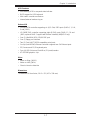
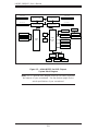
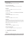
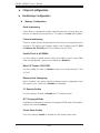
Figure 1-3. nVidia MCP55 Pro/IO55 Chipset:
System Block Diagram
Note: This is a general block diagram and may not exactly represent
the features on your serverboard. See the previous pages for the
actual specifi cations of your serverboard.
nVidia
MCP55
Pro
AMD Socket F Type
Processor (CPU2)
DDR2-667/533/400
DDR2-667/533/400
SATA Ports (6)
IDE (ATA133)
USB Ports (4)
S I/O BIOS
Floppy
Kybd/
Mouse
Serial Ports
(2)
AMD Socket F Type
Processor (CPU1)
PCI-E
LPC
ATI
ES 1000
nVidia
IO55
AMD Socket F Type
Processor (CPU3)
AMD Socket F Type
Processor (CPU4)
16 x 16 HT link (1 GHz)
NEC uPD720404
Slot #5: PCI-E x16
PCI-E x16
SIMLC
SATA
UDMA133
USB 2.0
DIMMs 1A ~ 4 B
DIMMs 1A ~ 4B
DIMMs 1A ~ 4B
DIMMs 1A ~ 4 B
Slot #2: PCI-E x16
Slot #3: PCI-E x8
Slot #4: PCI-E x4
SAS Ports (8)
PCI-E x8
PCI 32
Slot #1: PCI-X 133
LAN Ports (2)
PCI-E x4
DDR2-667/533/400
DDR2-667/533/400
16 x 16 HT link (1 GHz)

Chapter 1: Introduction
1-9
1-2 Chipset Overview
The H8QM3-2/H8QMi-2 serverboard is based on the nVidia MCP55 Pro and IO55
chipset. The MCP55 Pro functions as Media and Communications Processor (MCP)
and the IO55 as a PCI-E Tunnel. An NEC uPD720404 chip is also included as a
bridge for the GB LAN ports and the PCI-X slot. Note that the controllers for the
system memory are integrated directly into the AMD CPUs.
MCP55 Pro Media and Communications Processor
The MCP55 Pro is a single-chip, high-performance HyperTransport peripheral con-
troller. It includes a 28-lane PCI Express interface, an AMD Opteron 16-bit Hyper
Transport interface link, a six-port (3 Gb/s) Serial ATA interface, an ATA133 bus
master interface and a USB 2.0 interface. This hub connects directly to CPU1.
IO55
This hub connects directly to CPU2 via a 16 x 16 1 GHz Hyper Transport link. The
IO55 includes an interface for the PCI-Express slots.
NEC uPD720404
This I/O bridge chip provides one PCI-Express x4 upstream port and two PCI-X
domains. Each bridge supports PCI masters that include clock, request and grant
signals. This hub links the MCP55 with the PCI-X slot (slot #1) and the Gb LAN
ports.
HyperTransport Technology
HyperTransport technology is a high-speed, low latency point to point link that was
designed to increase the communication speed by a factor of up to 48x between
integrated circuits. This is done partly by reducing the number of buses in the
chipset to reduce bottlenecks and by enabling a more effi cient use of memory in
multi-processor systems. The end result is a signifi cant increase in bandwidth
within the chipset.

1-10
H8QM3-2/H8QMi-2 User’s Manual
1-3 PC Health Monitoring
This section describes the PC health monitoring features of the H8QM3-2/H8QMi-
2. The serverboard has an onboard System Hardware Monitor chip that supports
PC health monitoring.
Onboard Voltage Monitors for four CPU cores, Hyper Transport
(1.2V), memory (1.8V), chipset (1.5V)
The onboard voltage monitor will scan these voltages continuously. Once a voltage
becomes unstable, it will give a warning or send an error message to the screen.
Users can adjust the voltage thresholds to defi ne the sensitivity of the voltage moni-
tor. Real time readings of these voltage levels are all displayed in BIOS.
Fan Status Monitor with Firmware/Software Speed Control
The PC health monitor can check the RPM status of the cooling fans. The onboard
fans are controlled by thermal management via BIOS.
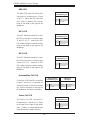
CPU Overheat/Fan Fail LED and Control
This feature is available when the user enables the CPU overheat/Fan Fail warning
function in the BIOS. This allows the user to defi ne an overheat temperature. When
this temperature is exceeded or when a fan failure occurs, then, the Overheat/Fan
Fail warning LED is triggered.
Auto-Switching Voltage Regulator for the CPU Core
The 5-phase-switching voltage regulator for the CPU core can support up to 100A
and auto-sense voltage IDs. This will allow the regulator to run cooler and thus
make the system more stable.
1-4 Power Confi guration Settings
This section describes the features of your serverboard that deal with power and
power settings.
Microsoft OnNow
The OnNow design initiative is a comprehensive, system-wide approach to system
and device power control. OnNow is a term for a PC that is always on but appears
to be off and responds immediately to user or other requests.

Chapter 1: Introduction
1-11
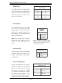
Slow Blinking LED for Suspend-State Indicator
When the CPU goes into a suspend state, the chassis power LED will start blinking
to indicate that the CPU is in suspend mode. When the user presses any key, the
CPU will wake-up and the LED will automatically stop blinking and remain on.
BIOS Support for USB Keyboard
If a USB keyboard is the only keyboard in the system, it will function like a normal
keyboard during system boot-up.
Main Switch Override Mechanism
When an ATX power supply is used, the power button can function as a system
suspend button. When the user depresses the power button, the system will enter
a SoftOff state. The monitor will be suspended and the hard drive will spin down.
Depressing the power button again will cause the whole system to wake-up. Dur-
ing the SoftOff state, the ATX power supply provides power to keep the required
circuitry in the system alive. In case the system malfunctions and you want to turn
off the power, just depress and hold the power button for 4 seconds. The power
will turn off and no power will be provided to the serverboard.
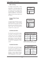
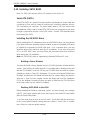
Wake-On-LAN
Wake-On-LAN is defi ned as the ability of a management application to remotely
power up a computer that is powered off. Remote PC setup, up-dates and access
tracking can occur after hours and on weekends so that daily LAN traffi c is kept
to a minimum and users are not interrupted. The serverboard has a 3-pin header
(JWOL) to connect to the 3-pin header on a Network Interface Card (NIC) that has
WOL capability. Wake-On-LAN must be enabled in BIOS. Note that Wake-On-LAN
can only be used with an ATX 2.01 (or above) compliant power supply.
Wake-On-Ring Header
Wake-up events can be triggered by a device such as the external modem ringing
when the system is in the SoftOff state. Note that external modem ring-on can only
be used with an ATX 2.01 (or above) compliant power supply.

1-12
H8QM3-2/H8QMi-2 User’s Manual
1-5 Power Supply
As with all computer products, a stable power source is necessary for proper and
reliable operation. It is even more important for processors that have high CPU
clock rates.
The H8QM3-2/H8QMi-2 accommodates 12V ATX power supplies. Although most
power supplies generally meet the specifi cations required by the CPU, some
are inadequate. A 2 amp current supply on a 5V Standby rail is strongly recom-
mended.
It is strongly recommended that you use a high quality power supply that meets
12V ATX power supply Specifi cation 1.1 or above. Additionally, in areas where
noisy power transmission is present, you may choose to install a line fi lter to shield
the computer from noise. It is recommended that you also install a power surge
protector to help avoid problems caused by power surges.
Warning: To prevent the possibility of explosion, do not use the wrong type of
onboard CMOS battery or install it upside down.
1-6 Super I/O
The disk drive adapter functions of the Super I/O chip include a fl oppy disk drive
controller that is compatible with industry standard 82077/765, a data separator,
write pre-compensation circuitry, decode logic, data rate selection, a clock genera-
tor, drive interface control logic and interrupt and DMA logic. The wide range of
functions integrated onto the Super I/O greatly reduces the number of components
required for interfacing with fl oppy disk drives. The Super I/O supports two 360
K, 720 K, 1.2 M, 1.44 M or 2.88 M disk drives and data transfer rates of 250 Kb/s,
500 Kb/s or 1 Mb/s.
It also provides two high-speed, 16550 compatible serial communication ports
(UARTs), one of which supports serial infrared communication. Each UART in-
cludes a 16-byte send/receive FIFO, a programmable baud rate generator, complete
modem control capability and a processor interrupt system. Both UARTs provide
legacy speed with baud rate of up to 115.2 Kbps as well as an advanced speed
with baud rates of 250 K, 500 K, or 1 Mb/s, which support higher speed modems.
The Super I/O provides functions that comply with ACPI (Advanced Confi guration
and Power Interface), which includes support of legacy and ACPI power manage-
ment through a SMI or SCI function pin. It also features auto power management
to reduce power consumption.
The IRQs, DMAs and I/O space resources of the Super I/O can be fl exibly adjusted
to meet ISA PnP requirements, which support ACPI and APM (Advanced Power
Management).

Chapter 2: Installation
2-1
Chapter 2
Installation
2-1 Static-Sensitive Devices
Electrostatic Discharge (ESD) can damage electronic com ponents. To prevent dam-
age to your system board, it is important to handle it very carefully. The following
measures are generally suffi cient to protect your equipment from ESD.
Precautions
• Use a grounded wrist strap designed to prevent static discharge.
• Touch a grounded metal object before removing the board from the antistatic
bag.
• Handle the board by its edges only; do not touch its components, peripheral
chips, memory modules or gold contacts.
• When handling chips or modules, avoid touching their pins.
• Put the serverboard and peripherals back into their antistatic bags when not in
use.
• For grounding purposes, make sure your computer chassis provides excellent
conductivity between the power supply, the case, the mounting fasteners and
the serverboard.
• Use only the correct type of CMOS onboard battery as specifi ed by the manufac-
turer. Do not install the CMOS onboard battery upside down, which may result
in a possible explosion.
Unpacking
The serverboard is shipped in antistatic packaging to avoid static damage. When
unpacking the board, make sure the person handling it is static protected.
Installation Procedures
Follow the procedures as listed below to install the serverboard into a chassis:
1. Install the processor(s) and the heatsink(s).
2. Install the serverboard in the chassis.
3. Install the memory and add-on cards.
4. Finally, connect the cables and install the drivers.

2-2
H8QM3-2/H8QMi-2 User's Manual
!
2-2 Processor and Heatsink Installation
Installing Processors
CPU Backplates
Four CPU backplates (BKT-0011L) have been preinstalled to the serverboard to
prevent the CPU area of the serverboard from bending and to provide a base for
attaching the heatsink retention modules.
Single, dual or quad-CPU confi gurations only are supported. For a single-CPU
confi guration, install to the CPU1 socket. For a dual-CPU confi guration, install to
the CPU1 and CPU2 sockets.
Exercise extreme caution when handling and installing the proces-
sor. Always connect the power cord last and always remove it be-
fore adding, removing or changing any hardware components.
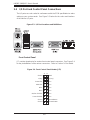
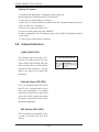
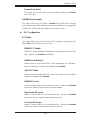
1. Begin by removing the cover plate
that protects the CPU. Lift the lever on
the CPU socket until it points straight
up. With the lever raised, lift open the
silver CPU retention plate.
2. Use your thumb and your index
fi nger to hold the CPU. Locate and
align pin 1 of the CPU socket with pin
1 of the CPU. Both are marked with
a triangle.
Triangles
Page is loading ...
Page is loading ...
Page is loading ...
Page is loading ...
Page is loading ...
Page is loading ...
Page is loading ...
Page is loading ...
Page is loading ...
Page is loading ...
Page is loading ...
Page is loading ...
Page is loading ...
Page is loading ...
Page is loading ...
Page is loading ...
Page is loading ...
Page is loading ...
Page is loading ...
Page is loading ...
Page is loading ...
Page is loading ...
Page is loading ...
Page is loading ...
Page is loading ...
Page is loading ...
Page is loading ...
Page is loading ...
Page is loading ...
Page is loading ...
Page is loading ...
Page is loading ...
Page is loading ...
Page is loading ...
Page is loading ...
Page is loading ...
Page is loading ...
Page is loading ...
Page is loading ...
Page is loading ...
Page is loading ...
Page is loading ...
Page is loading ...
Page is loading ...
Page is loading ...
Page is loading ...
Page is loading ...
Page is loading ...
Page is loading ...
Page is loading ...
Page is loading ...
Page is loading ...
Page is loading ...
Page is loading ...
Page is loading ...
Page is loading ...
-
 1
1
-
 2
2
-
 3
3
-
 4
4
-
 5
5
-
 6
6
-
 7
7
-
 8
8
-
 9
9
-
 10
10
-
 11
11
-
 12
12
-
 13
13
-
 14
14
-
 15
15
-
 16
16
-
 17
17
-
 18
18
-
 19
19
-
 20
20
-
 21
21
-
 22
22
-
 23
23
-
 24
24
-
 25
25
-
 26
26
-
 27
27
-
 28
28
-
 29
29
-
 30
30
-
 31
31
-
 32
32
-
 33
33
-
 34
34
-
 35
35
-
 36
36
-
 37
37
-
 38
38
-
 39
39
-
 40
40
-
 41
41
-
 42
42
-
 43
43
-
 44
44
-
 45
45
-
 46
46
-
 47
47
-
 48
48
-
 49
49
-
 50
50
-
 51
51
-
 52
52
-
 53
53
-
 54
54
-
 55
55
-
 56
56
-
 57
57
-
 58
58
-
 59
59
-
 60
60
-
 61
61
-
 62
62
-
 63
63
-
 64
64
-
 65
65
-
 66
66
-
 67
67
-
 68
68
-
 69
69
-
 70
70
-
 71
71
-
 72
72
-
 73
73
-
 74
74
-
 75
75
-
 76
76


SUPER MICRO Computer H8QM3-2 User manual
- Category
- Server/workstation motherboards
- Type
- User manual
- This manual is also suitable for
Ask a question and I''ll find the answer in the document
Finding information in a document is now easier with AI
Related papers
-
SUPER MICRO Computer H8QMi-2 User manual
-
-
SUPER MICRO Computer H8QME-2 User manual
-
-
-
-
SUPER MICRO Computer H8DMT-IBXF User manual
-
Other documents
-
Supermicro H8QM3-2+ User manual
-
-
-
-
-
-
-
Vantec UGT-PC205 User manual
-
Supermicro A+ Server 1041M-T2, Beige User manual
-