JBL CONTROL 2.4G Owner's manual
- Category
- Loudspeakers
- Type
- Owner's manual
This manual is also suitable for
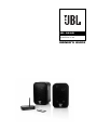
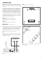
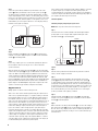
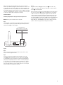
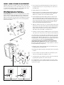
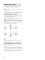
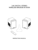
JBL On Air Control 2.4G is a wireless loudspeaker system that lets you enjoy music remotely or add surround speakers to your home theater without running wires. The system includes a transmitter module, a power supply for the transmitter, an active speaker/receiver, a power supply for the active speaker, a passive speaker, wall-mount brackets for the speakers, a remote control, and interconnect cables.
JBL On Air Control 2.4G is a wireless loudspeaker system that lets you enjoy music remotely or add surround speakers to your home theater without running wires. The system includes a transmitter module, a power supply for the transmitter, an active speaker/receiver, a power supply for the active speaker, a passive speaker, wall-mount brackets for the speakers, a remote control, and interconnect cables.


-
 1
1
-
 2
2
-
 3
3
-
 4
4
-
 5
5
-
 6
6
-
 7
7
-
 8
8
-
 9
9
-
 10
10
-
 11
11
-
 12
12


JBL CONTROL 2.4G Owner's manual
- Category
- Loudspeakers
- Type
- Owner's manual
- This manual is also suitable for
JBL On Air Control 2.4G is a wireless loudspeaker system that lets you enjoy music remotely or add surround speakers to your home theater without running wires. The system includes a transmitter module, a power supply for the transmitter, an active speaker/receiver, a power supply for the active speaker, a passive speaker, wall-mount brackets for the speakers, a remote control, and interconnect cables.
Ask a question and I''ll find the answer in the document
Finding information in a document is now easier with AI
Related papers
-
JBL ON AIR CONTROL 2.4G AW (220-240V) User manual
-
JBL CONTROL 2.4G Owner's manual
-
-
-
JBL Control One Owner's manual
-
JBL Control X Owner's manual
-
-
-
-
Other documents
-
Pure Acoustics HT 770 User manual
-
 Acoustic Arc AAI-DS0820US0 User manual
-
Acoustic Research AW825 User manual
-
Acoustic Research AWS5 Operating instructions
-
-
Yamaha NS-FP9500 User manual
-
Rockville Cube 70v Owner's manual
-
-
-
